An ultrafast rechargeable aluminium-ion battery
An ultrafast rechargeable aluminium-ion battery
Meng-Chang Lin 1,2*,Ming Gong 1*,Bingan Lu 1,3*,Yingpeng Wu 1*,Di-Yan W ang 1,4,5,Mingyun Guan 1,Michael Angell 1,Changxin Chen 1,Jiang Yang 1,Bing-Joe Hwang 6&Hongjie Dai 1
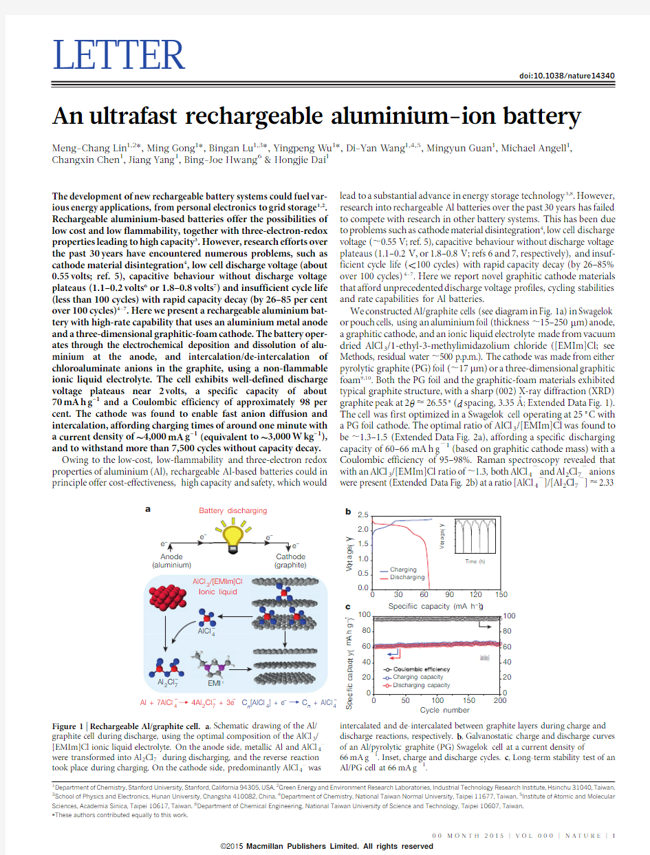
The development of new rechargeable battery systems could fuel var-ious energy applications,from personal electronics to grid storage 1,2.Rechargeable aluminium-based batteries offer the possibilities of low cost and low flammability,together with three-electron-redox properties leading to high capacity 3.However,research efforts over the past 30years have encountered numerous problems,such as cathode material disintegration 4,low cell discharge voltage (about 0.55volts;ref.5),capacitive behaviour without discharge voltage plateaus (1.1–0.2volts 6or 1.8–0.8volts 7)and insufficient cycle life (less than 100cycles)with rapid capacity decay (by 26–85per cent over 100cycles)4–7.Here we present a rechargeable aluminium bat-tery with high-rate capability that uses an aluminium metal anode and a three-dimensional graphitic-foam cathode.The battery oper-ates through the electrochemical deposition and dissolution of alu-minium at the anode,and intercalation/de-intercalation of chloroaluminate anions in the graphite,using a non-flammable ionic liquid electrolyte.The cell exhibits well-defined discharge voltage plateaus near 2volts,a specific capacity of about 70mA h g –1and a Coulombic efficiency of approximately 98per cent.The cathode was found to enable fast anion diffusion and intercalation,affording charging times of around one minute with a current density
of 4,000mA g –1(equivalent to 3,000W kg –1),and to withstand more than 7,500cycles without capacity decay.Owing to the low-cost,low-flammability and three-electron redox properties of aluminium (Al),rechargeable Al-based batteries could in principle offer cost-effectiveness,high capacity and safety,which would
lead to a substantial advance in energy storage technology 3,8.However,research into rechargeable Al batteries over the past 30years has failed to compete with research in other battery systems.This has been due to problems such as cathode material disintegration 4,low cell discharge voltage (,0.55V;ref.5),capacitive behaviour without discharge voltage plateaus (1.1–0.2V,or 1.8–0.8V;refs 6and 7,respectively),and insuf-ficient cycle life (,100cycles)with rapid capacity decay (by 26–85%over 100cycles)4–7.Here we report novel graphitic cathode materials that afford unprecedented discharge voltage profiles,cycling stabilities and rate capabilities for Al batteries.
We constructed Al/graphite cells (see diagram in Fig.1a)in Swagelok or pouch cells,using an aluminium foil (thickness ,15–250m m)anode,a graphitic cathode,and an ionic liquid electrolyte made from vacuum dried AlCl 3/1-ethyl-3-methylimidazolium chloride ([EMIm]Cl;see Methods,residual water ,500p.p.m.).The cathode was made from either pyrolytic graphite (PG)foil (,17m m)or a three-dimensional graphitic foam 9,10.Both the PG foil and the graphitic-foam materials exhibited typical graphite structure,with a sharp (002)X-ray diffraction (XRD)
graphite peak at 2h <26.55u (d spacing,3.35A
?;Extended Data Fig.1).The cell was first optimized in a Swagelok cell operating at 25u C with a PG foil cathode.The optimal ratio of AlCl 3/[EMIm]Cl was found to be ,1.3–1.5(Extended Data Fig.2a),affording a specific discharging capacity of 60–66mA h g 21(based on graphitic cathode mass)with a Coulombic efficiency of 95–98%.Raman spectroscopy revealed that with an AlCl 3/[EMIm]Cl ratio of ,1.3,both AlCl 42and Al 2Cl 72anions were present (Extended Data Fig.2b)at a ratio [AlCl 42]/[Al 2Cl 72]<2.33
*These authors contributed equally to this work.
1Department of Chemistry,Stanford University,Stanford,California 94305,USA.2Green Energy and Environment Research Laboratories,Industrial Technology Research Institute,Hsinchu 31040,Taiwan.3
School of Physics and Electronics,Hunan University,Changsha 410082,China.4Department of Chemistry,National Taiwan Normal University,Taipei 11677,Taiwan.5Institute of Atomic and Molecular Sciences,Academia Sinica,Taipei 10617,Taiwan.6Department of Chemical Engineering,National Taiwan University of Science and Technology,Taipei 10607,Taiwan.
360
365
370
0.00.51.01.52.0
2.5V o l t a g
e (V
)
Time (h)
Cycle number
Specific capacity (mA h g –1)
e –4
Battery discharging a
b c
(aluminium)
(graphite)
C n [AlCl 4] + e
C n + AlCl 4
EMI +
Al 2Cl 7
4Al 2Cl 7 + 3e
AlCl 3/[EMIm]Cl Ionic liquid
Al + 7AlCl 4
3060901201500.0
0.51.01.52.02.5
Charging Discharging
V o l t a g e (V )
S p e c i fi c c a p a c i t y (m A h g –1)
Coulombic efficiency (%)
–
––
––
–
–
Figure 1|Rechargeable Al/graphite cell.a ,Schematic drawing of the Al/graphite cell during discharge,using the optimal composition of the AlCl 3/[EMIm]Cl ionic liquid electrolyte.On the anode side,metallic Al and AlCl 4–were transformed into Al 2Cl 7–during discharging,and the reverse reaction took place during charging.On the cathode side,predominantly AlCl 4–was
intercalated and de-intercalated between graphite layers during charge and discharge reactions,respectively.b ,Galvanostatic charge and discharge curves of an Al/pyrolytic graphite (PG)Swagelok cell at a current density of
66mA g 21.Inset,charge and discharge cycles.c ,Long-term stability test of an Al/PG cell at 66mA g 21.
00M O N T H 2015|V O L 000|N A T U R E |1
Macmillan Publishers Limited. All rights reserved
?2015
(ref.11).The cathode specific discharging capacity was found to be independent of graphite mass (Extended Data Fig.3),suggesting that the entirety of the graphite foil participated in the cathode reaction.The Al/PG cell exhibited clear discharge voltage plateaus in the ranges 2.25–2.0V and 1.9–1.5V (Fig.1b).The relatively high discharge voltage plateaus are unprecedented among all past Al-ion charge-storage sys-tems 4–7.Similar cell operation was observed with the amount of elec-trolyte lowered to ,0.02ml per mg of cathode material (Extended Data Fig.4).Charge–discharge cycling at a current density of 66mA g 21(1C charging rate)demonstrated the high stability of the Al/PG cell,which nearly perfectly maintained its specific capacity over .200cycles with a 98.160.4%Coulombic efficiency (Fig.1c).This was consistent with the high reversibility of Al dissolution/deposition,with Coulombic efficiencies of 98.6–99.8%in ionic liquid electrolytes 12–15.No dendrite formation was observed on the Al electrode after cycling (Extended Data Fig.5).To maintain a Coulombic efficiency .96%,the cut-off voltage of the Al/PG cell (that is,the voltage at which charging was stopped)was set at 2.45V,above which reduced efficiencies were observed (see Extended Data Fig.6a),probably due to side reactions (especially above ,2.6V)involving the electrolyte,as probed by cyclic voltamme-try with a glassy carbon electrode against Al (Extended Data Fig.6b).We observed lowered Coulombic efficiency and cycling stability of the Al/graphite cell when using electrolytes with higher water contents,up to ,7,500p.p.m.(Extended data Fig.6c,d),accompanied by obvious H 2gas evolution measured by gas chromatography (Extended Data Fig.6e).This suggested side reactions triggered by the presence of resi-dual water in the electrolyte,with H 2evolution under reducing poten-tial on the Al side during charging.Further lowering the water content
of the ionic liquid electrolyte could be important when maximizing the Coulombic efficiency of the Al/graphite cells.
The Al/PG cell showed limited rate capability with much lower specific capacity when charged and discharged at a rate higher than 1C (Extended Data Fig.7).It was determined that cathode reactions in the Al/PG cell involve intercalation and de-intercalation of relatively large chloroa-luminate (Al x Cl y 2)anions in the graphite (see below for XRD evidence of intercalation),and the rate capability is limited by slow diffusion of anions through the graphitic layers 16.When PG was replaced by nat-ural graphite,intercalation was evident during charging owing to dra-matic expansion (,50-fold)of the cathode into loosely stacked flakes visible to the naked eye (Extended Data Fig.8a).In contrast,expansion of PG foil upon charging the Al/PG cell was not observable by eye (Extended Data Fig.8b),despite the similar specific charging capacity of the two materials (Extended Data Fig.8c).This superior structural integrity of PG over natural graphite during charging was attributed to the existence of covalent bonding between adjacent graphene sheets in PG 17,which was not present in natural https://www.360docs.net/doc/fd13942702.html,ing PG,which has an open,three-dimensionally-bound graphitic structure,we prevented excessive electrode expansion that would lead to electrode disinteg-ration,while maintaining the efficient anion intercalation necessary for high performance.
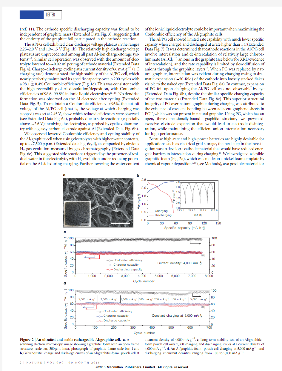
Because high-rate and high-power batteries are highly desirable for applications such as electrical grid storage,the next step in the investi-gation was to develop a cathode material that would have reduced ener-getic barriers to intercalation during charging 16.We investigated a flexible graphitic foam (Fig.2a),which was made on a nickel foam template by chemical vapour deposition 9,10(see Methods),as a possible material for
d
c
b
Cycle number
Specific capacity (mA h g –1)
a
30
6090120150
0.0
0.51.01.52.02.5
Charging Discharging
V o l t a g e (V )
223.5
223.6
223.7
223.8
0.00.51.01.52.02.5V o l t a g e (V )
Time (h)
Cycle number
Coulombic efficiency (%)
Coulombic efficiency (%)
S p e c i fi c c a p a c i t y (m A h g –1)S p e c i fi c c a p a c i t y (m A h g –1)Figure 2|An ultrafast and stable rechargeable Al/graphite cell.a ,A
scanning electron microscopy image showing a graphitic foam with an open frame structure;scale bar,300m m.Inset,photograph of graphitic foam;scale bar,1cm.b ,Galvanostatic charge and discharge curves of an Al/graphitic-foam pouch cell at
a current density of 4,000mA g 21.c ,Long-term stability test of an Al/graphitic-foam pouch cell over 7,500charging and discharging cycles at a current density of 4,000mA g 21.d ,An Al/graphitic-foam pouch cell charging at 5,000mA g 21and discharging at current densities ranging from 100to 5,000mA g 21.
RESEARCH LETTER
2|N A T U R E |V O L 000|00M O N T H 2015
Macmillan Publishers Limited. All rights reserved
?2015
ultrafast Al batteries.The graphite whiskers in the foam were 100m m in width (Fig.2a),with large spaces in between,which greatly decreased the diffusion length for the intercalating electrolyte anions and facili-tated more rapid battery operation.
Remarkably,the Al/graphitic-foam cell (in a pouch cell configuration)could be charged and discharged at a current density up to 5,000mA g 21,about 75times higher (that is,at a 75C rate,,1min charge/discharge time)than the Al/PG cell while maintaining a similar voltage profile and discharge capacity (,60mA h g 21)(Figs 1b and 2b).An impres-sive cycling stability with ,100%capacity retention was observed over 7,500cycles with a Coulombic efficiency of 9762.3%(Fig.2c).This is the first time an ultrafast Al-ion battery has been constructed with stability over thousands of cycles.The Al/graphitic-foam cell retained similar capacity and excellent cycling stability over a range of charge–discharge rates (1,000–6,000mA g 21)with 85299%Coulombic effi-ciency (Extended Data Fig.9a).It was also found that this cell could be rapidly charged (at 5,000mA g 21,in ,1min)and gradually discharged (down to 100mA g 21,Fig.2d and Extended Data Fig.9b)over ,34min while maintaining a high capacity (,60mA h g 21).Such a rapid char-ging/variable discharging rate could be appealing in many real-world applications.
We propose that simplified Al/graphite cell redox reactions during charging and discharging can be written as:
4Al 2Cl {7z 3e {
'Al z 7AlCl {4e1TC n z AlCl {4'C n AlCl 4? z e
{e2T
where n is the molar ratio of carbon atoms to intercalated anions in the
graphite.The balanced AlCl 4–and Al 2Cl 7–concentrations in the electro-lyte allowed for an optimal charging capacity at the cathode,with abun-dant AlCl 4–for charging/intercalation in graphite (equation (2)),and sufficient Al 2Cl 7–concentration for charging/electrodeposition at the anode (equation (1).
Ex situ XRD measurement of graphite foil (Fig.3a)confirmed graphite intercalation/de-intercalation by chloroaluminate anions during charging/discharging.The sharp pristine graphite foil (002)peak at
2h 526.55u (d spacing 53.35A
?)(Fig.3a)vanished on charging to a specific capacity of ,30mA h g –1,while two new peaks appeared at
,28.25u (d <3.15A
?)and ,23.56u (d <3.77A ?)(Fig.3a),with peak intensities further increasing on fully charging to ,62mA h g –1.The doublet XRD peak suggested highly strained graphene stacks formed on anion intercalation 18.Analysis of the peak separation (see Methods)suggested a stage 4graphite intercalation compound with an interca-lant gallery height (spacing between adjacent graphitic host layers)of
,5.7A
?,indicating that the AlCl 4–anions (size ,5.28A ?;ref.19)were intercalated between graphene layers in a distorted state.Full dischar-ging led to the recovery of the graphite peak but with a broad shoulder (Fig.3a),probably caused by irreversible changes in the stacking between the graphene layers or a small amount of trapped species.In situ Raman spectroscopy was also performed to probe chloroalu-minate anion intercalation/de-intercalation from graphite during cell charge/discharge (Fig.3b).The graphite G band (,1,584cm –1)diminished and split into a doublet (1,587cm –1for the E 2g2(i)mode and ,1,608cm –1for the E 2g2(b)mode)upon anion intercalation (Fig.3b)20,and then evolved into a sharp new peak (,1,636cm –1,the G2band of the E 2g2(b)mode,spectrum 2.41V,Fig.3b)once fully charged.The spectral changes were then reversed upon discharging (Fig.3b),as the typical graphite Raman G band (1584cm –1)was recovered when fully discharged (spectrum 0.03V,Fig.3b).Similar Raman spectra and XRD data were obtained with a graphitic-foam cathode (Extended Data Fig.10a,b).Interestingly,calcination of a fully charged PG foil at 850u C in air (Fig.3c)yielded a white aluminium oxide foam (Extended Data Fig.10c),confirming the intercalation of chloroaluminate anions into the carbon network,which had been evi-dently removed oxidatively.
Lastly,X-ray photoelectron spectra (XPS)and Auger electron spec-troscopy (AES)were performed to probe the chemical nature of the intercalated species in our graphitic cathodes (see Methods for details).To minimize the amount of trapped electrolyte,graphitic foam was used and the electrode was thoroughly washed with anhydrous methanol.XPS revealed that upon charging pristine graphite,the 284.8eV C 1s peak developed a shoulder at higher energy (,285.9eV,Fig.4a),con-firming electrochemical oxidation of graphitic carbon by intercalation of AlCl 4–anions (equation (2)).Chloroaluminate intercalation was evi-dent from the appearance of Al 2p and Cl 2p peaks (Fig.4b,c).Upon
Fully charged PG
850°C in air
c
b
a
20253035
discharged charged
charged 30 mA h g –124 mA h g –1I n t e n s i t y (a .u .)
62 mA h g –1Pristine
discharged 60 mA h g –13.77 ?
3.35 ?
3.15 ?
Second cycle
I n t e n s i t y (a .u .)
Raman shift (cm –1)
2q (degrees)
Figure 3|Al/graphite cell reaction mechanisms.a ,Ex situ X-ray diffraction patterns of PG in various charging and discharging states through the second cycle.b ,In situ Raman spectra recorded for the PG cathode through a charge–discharge cycle,showing chloroaluminate anion intercalation/de-intercalation into graphite.c ,After calcination of a fully charged
(62mA h g 21)PG electrode at 850u C in air,the sample completely transformed into a white foam made of aluminium oxide.Scale bar,1cm.
I n t e n s i t y (a .u .)
Binding energy (eV)
400
8001,2001,6002,000
–2.0
–1.00.01.0
2.0C l O
C d N (E )/d E (×104)
d N (E )/d E (×104)
Kinetic energy (eV)
Al
Discharged cathode
Charged cathode
C+Al+Cl
f e
d
g
c
Kinetic energy (eV)
Figure 4|Chemical probing of a graphitic cathode by XPS and AES.a ,XPS data of the C 1s peak of a graphitic-foam electrode:pristine,fully charged and fully discharged.b ,c ,XPS data of Al 2p and Cl 2p peaks observed with a graphitic-foam electrode:pristine,fully charged and fully discharged.d–g ,AES mapping images for C,Al and Cl (d ,f ),and the AES spectrum of the boxed regions (e ,g )obtained with a fully charged graphitic-foam sample (d ,e )and a fully discharged graphitic-foam sample (f ,g ).Scale bars:d ,25m m;f ,10m m.
LETTER RESEARCH
00M O N T H 2015|V O L 000|N A T U R E |3
Macmillan Publishers Limited. All rights reserved
?2015
discharging,the C1s XPS spectrum of the cathode reverted to that of the pristine graphite due to anion de-intercalation and carbon reduc-tion(Fig.4a).Also,a substantial reduction in the Al2p and Cl2p signals was recorded over the graphite sample(see Fig.4b,c).The remaining Al and Cl signals observed were attributed to trapped/adsorbed species in the graphite sample,which was probed by XPS over a large area.Fur-thermore,high spatial resolution AES elemental mapping of a single graphite whisker in the fully charged graphitic foam clearly revealed Al and Cl Auger signals uniformly distributed over the whisker(Fig.4d,e), again confirming chloroaluminate anion intercalation.When fully dis-charged,AES mapping revealed anion de-intercalation from graphite with much lower Al and Cl Auger signals observed(Fig.4f,g).These spectroscopic results clearly revealed chloroaluminate ion intercala-tion/de-intercalation in the graphite redox reactions involved in our rechargeable Al cell.
The Al battery pouch cell is mechanically bendable and foldable(Sup-plementary Video1)owing to the flexibility of the electrode and sepa-rator materials.Further,we drilled through Al battery pouch cells during battery operation and observed no safety hazard,owing to the lack of flammability of the ionic liquid electrolyte in air(see Supplementary Video2).
We have developed a new Al-ion battery using novel graphitic cath-ode materials with a stable cycling life up to7,500charge/discharge cycles without decay at ultrahigh current densities.The present Al/graphite battery can afford an energy density of,40W h kg–1(comparable to lead–acid and Ni–MH batteries,with room for improvement by opti-mizing the graphitic electrodes and by developing other novel cathode materials)and a high power density,up to3,000W kg–1(similar to super-capacitors).We note that the energy/power densities were calculated on the basis of the measured,65mA h g–1cathode capacity and the mass of active materials in electrodes and electrolyte.Such recharge-able Al ion batteries have the potential to be cost effective and safe,and to have high power density.
Online Content Methods,along with any additional Extended Data display items and Source Data,are available in the online version of the paper;references unique to these sections appear only in the online paper.
Received12March2014;accepted6February2015.
Published online6April2015.
1.Yang,Z.et al.Electrochemical energy storage for green grid.Chem.Rev.111,
3577–3613(2011).
2.Huskinson,B.et al.A metal-free organic-inorganic aqueous flow battery.Nature
505,195–198(2014).
3.Li,Q.&Bjerrum,N.J.Aluminum as anode for energy storage and conversion:a
review.J.Power Sources110,1–10(2002).
4.Gifford,P.R.&Palmisano,J.B.An aluminum/chlorine rechargeable cell
employing a room temperature molten salt electrolyte.J.Electrochem.Soc.135, 650–654(1988).
5.Jayaprakash,N.,Das,S.K.&Archer,L.A.The rechargeable aluminum-ion battery.
https://www.360docs.net/doc/fd13942702.html,mun.47,12610–12612(2011).
6.Rani,J.V.,Kanakaiah,V.,Dadmal,T.,Rao,M.S.&Bhavanarushi,S.Fluorinated
natural graphite cathode for rechargeable ionic liquid based aluminum-ion
battery.J.Electrochem.Soc.160,A1781–A1784(2013).7.Hudak,N.S.Chloroaluminate-doped conducting polymers as positive electrodes
in rechargeable aluminum batteries.J.Phys.Chem.C118,5203–5215(2014).
8.Armand,M.&Tarascon,J.M.Building better batteries.Nature451,652–657
(2008).
9.Yu,X.,Lu,B.&Xu,Z.Super long-life supercapacitors based on the construction of
nanohoneycomb-like strongly coupled CoMoO4–3D graphene hybrid electrodes.
Adv.Mater.26,1044–1051(2014).
10.Chen,Z.et al.Three-dimensional flexible and conductive interconnected graphene
networks grown by chemical vapour deposition.Nature Mater.10,424–428
(2011).
11.Wasserscheid,P.&Keim,W.Ionic liquids—new‘‘solutions’’for transition metal
catalysis.Angew.Chem.Int.Edn39,3772–3789(2000).
12.Auborn,J.J.&Barberio,Y.L.An ambient temperature secondary aluminum
electrode:its cycling rates and its cycling efficiencies.J.Electrochem.Soc.132, 598–601(1985).
13.Wilkes,J.S.,Levisky,J.A.,Wilson,R.A.&Hussey,C.L.Dialkylimidazolium
chloroaluminate melts:a new class of room-temperature ionic liquids for
electrochemistry,spectroscopy and synthesis.Inorg.Chem.21,1263–1264(1982).
https://www.360docs.net/doc/fd13942702.html,i,P.K.&Skyllas-Kazacos,M.Electrodeposition of aluminium in aluminium
chloride/1-methyl-3-ethylimidazolium chloride.J.Electroanal.Chem.Interfacial Electrochem.248,431–440(1988).
15.Jiang,T.,Chollier Brym,M.J.,Dube′,G.,Lasia,A.&Brisard,G.M.Electrodeposition of
aluminium from ionic liquids:Part I—electrodeposition and surface morphology of aluminium from aluminium chloride(AlCl3)–1-ethyl-3-methylimidazolium chloride([EMIm]Cl)ionic liquids.Surf.Coat.Tech.201,1–9(2006).
16.Borg,R.J.&Dienes,G.J.An Introduction to Solid State Diffusion(Academic,1988).
17.Zhu,Y.-J.,Hansen,T.A.,Ammermann,S.,McBride,J.D.&Beebe,T.P.Nanometer-
size monolayer and multilayer molecule corrals on HOPG:a depth-resolved
mechanistic study by STM.J.Phys.Chem.B105,7632–7638(2001).
18.Schmuelling,G.et al.X-ray diffraction studies of the electrochemical intercalation
of bis(trifluoromethanesulfonyl)imide anions into graphite for dual-ion cells.
J.Power Sources239,563–571(2013).
19.Takahashi,S.,Koura,N.,Kohara,S.,Saboungi,M.L.&Curtiss,L.A.Technological
and scientific issues of room-temperature molten salts.Plasmas Ions2,91–105 (1999).
20.Hardwick,L.J.et al.An in situ Raman study of the intercalation of supercapacitor-
type electrolyte into microcrystalline graphite.Electrochim.Acta52,675–680 (2006).
Supplementary Information is available in the online version of the paper. Acknowledgements We thank M.D.Fayer for discussions.We also thank Y.Cui’s group for use of an argon-filled glove box and a vacuum oven.M.-C.L thanks the Bureau of Energy,Ministry of Economic Affairs,Taiwan,for supporting international cooperation between Stanford University and ITRI.B.L.acknowledges support from the National Natural Science Foundation of China(grant no.21303046),the China Scholarship Council(no.201308430178),and the Hunan University Fund for Multidisciplinary Developing(no.531107040762).We also acknowledge support from the US Department of Energy for novel carbon materials development and electrical characterization work(DOE DE-SC0008684),Stanford GCEP,the Precourt Institute of Energy,and the Global Networking Talent3.0plan(NTUST104DI005)from the Ministry of Education of Taiwan.
Author Contributions M.-C.L.,M.G.,B.L.and Y.W.contributed equally to this work. M.-C.L.and H.D.conceived the idea for the project.B.L.prepared the graphitic foam. M.-C.L.,M.G.,B.L.,Y.W.,D.-Y.W.,M.A.and M.Guan performed electrochemical experiments.M.-C.L.,C.C.and J.Y conducted in situ Raman spectroscopy measurements.M.-C.L.,M.G.,B.L.and Y.W.performed ex situ X-ray diffraction measurements.M.G.,M.-C.L.,B.L.and Y.W.performed X-ray photoelectron spectroscopy and Auger electron spectroscopy measurements.M.-C.L.,M.G.,B.L.,Y.W., D.-Y.W.,M.A.,B.-J.H.and H.D.discussed the results,analysed the data and drafted the manuscript.
Author Information Reprints and permissions information is available at
https://www.360docs.net/doc/fd13942702.html,/reprints.The authors declare no competing financial interests. Readers are welcome to comment on the online version of the paper.Correspondence and requests for materials should be addressed to H.D.(hdai@https://www.360docs.net/doc/fd13942702.html,).
RESEARCH LETTER
4|N A T U R E|V O L000|00M O N T H2015
Macmillan Publishers Limited. All rights reserved
?2015
METHODS
Preparation of ionic liquid electrolytes.A room temperature ionic liquid electro-lyte was made by mixing1-ethyl-3-methylimidazolium chloride([EMIm]Cl,97%, Acros Chemicals)and anhydrous aluminium chloride(AlCl3,99.999%,Sigma Aldrich).[EMIm]Cl was baked at130u C under vacuum for16–32h to remove residual water.([EMIm]Al x Cl y)ionic liquid electrolytes were prepared in an argon-atmosphere glove box(both[EMIm]Cl and AlCl3are highly hygroscopic)by mix-ing anhydrous AlCl3with[EMIm]Cl,and the resulting light-yellow,transparent liquid was stirred at room temperature for10min.The mole ratio of AlCl3to[EMIm]Cl was varied from1.1to1.8.The water content of the ionic liquid was determined (500–700p.p.m.)using a coulometric Karl Fischer titrator,DL39(Mettler Toledo). The predominant anions in basic melts(AlCl3/[EMIm]Cl mole ratio,1)are Cl2 and AlCl42,while in acidic melts(AlCl3/[EMIm]Cl mole ratio.1)chloroalumi-nate anions such as Al2Cl72,Al3Cl102,and Al4Cl132are formed11.The ratio of anions to cations in the AlCl3/[EMIm]Cl electrolyte was determined using a glass fibre filter paper(Whatman GF/D)loaded with a4–8m m Au-coated SiO2beads21in a cuvette cell(0.35ml,Starna Cells)with random orientation quartz windows.Then,in the glove box,the cuvette cell was filled with AlCl3/[EMIm]Cl51.3(by mole).Raman spectra(200–650cm-1)were obtained using a785-nm laser with2cm–1resolution. Raman data were collected from the surface of the Au-coated SiO2bead so as to benefit from surface enhanced Raman21,22(Extended Data Fig.2b). Preparation of graphitic foam.Nickel(Ni)foams(Alantum Advanced Technology Materials,Shenyang,China),were used as3D scaffold templates for the CVD growth of graphitic foam,following the process reported previously9,10. The Ni foams were heated to1,000u C in a horizontal tube furnace(Lindberg Blue M,TF55030C)under Ar(500standard cubic centimetres per minute or s.c.c.m.)and H2(200s.c.c.m.)and annealed for10min to clean their surfaces and to eliminate a thin surface oxide layer.Then,methane(CH4)was introduced into the reaction tube at ambient pressure at a flow rate of10s.c.c.m.,corresponding to a concen-tration of1.4vol.%in the total gas flow.After10min of reaction gas mixture flow, the samples were rapidly cooled to room temperature at a rate of300u C min21 under Ar(500s.c.c.m.)and H2(200s.c.c.m.).The Ni foams covered with graphite were drop-coated with a poly(methyl methacrylate)(PMMA)solution(4.5%in ethyl acetate),and then baked at110u C for0.5h.The PMMA/graphene/Ni foam structure was obtained after solidification.Afterwards,these samples were put into a3M HCl solution for3h to completely dissolve the Ni foam to obtain the PMMA/graphite at80u C.Finally,the pure graphitic foam was obtained by removing PMMA in hot acetone at55u C and annealing in NH3(80s.c.c.m.)at 600u C for2h,and then annealing in air at450u C for2h.The microstructure of the graphitic foam was examined by SEM analysis using a FEI XL30Sirion scanning electron microscope(Fig.2a in the main text).
Preparation of glassy carbon.Glassy carbon(GC)was used as the current collector in the Swagelok-type cell.72g phenol(Sigma-Aldrich)and4.5ml ammonium hydroxide(30%,Fisher Scientific)were dissolved in100ml formaldehyde solution (37%,Fisher Scientific)under reflux while stirring rapidly.The solution was stirred at90u C until the solution turned a milk-white colour.Rotary evaporation was used to remove the water and get the phenolic resin.The phenolic resin was solidified at 100u C in a mould(1/2-inch glass tube),and then carbonized at850u C under an Ar atmosphere for four hours to obtain the GC rod.The resulting GC rod contributed negligible capacity to the cathode(Extended Data Fig.6b).
Electrochemical measurements.Prior to assembling the Al/graphite cell in the glove box,all components were heated under vacuum at60u C for more than12h to remove residual water.All electrochemical tests were performed at2561u C.
A Swagelok-type cell(1/2inch diameter)was constructed using a,4mg PG foil
(0.017mm,Suzhou Dasen Electronics Materials)cathode and a90mg Al foil (0.25mm,Alfa Aesar)anode.A1/2inch GC rod(10mm)was used as the current collector for the PG cathode,and a1/2inch graphite rod(10mm)was used for the Al anode.Six layers of1/2inch glass fibre filter paper(Whatman934-AH)were placed between the anode and cathode.Then,,1.0ml of ionic liquid electrolyte (prepared with AlCl3/[EMIm]Cl mole ratios of1.1,1.3,1.5and1.8)was injected and the cell sealed.The Al/PG cell was then charged(to2.45V)and discharged(to 0.01V)at a current density of66mA g–1with a MTI battery analyser(BST8-WA) to identify the ideal AlCl3/[EMIm]Cl mole ratio(Extended Data Fig.2a).To investigate the Coulombic efficiency of the Al/PG cell in AlCl3/[EMIm]Cl<1.3 (by mole)electrolyte,the cell was charged to2.45,2.50,2.55and2.60V,respectively, and discharged to0.4V at a current density of66mA g–1(Extended Data Fig.6a). For long-term cycling stability tests,an Al/PG cell using electrolyte AlCl3/ [EMIm]Cl<1.3by mole was charged/discharged at a current density of 66mA g21(Fig.1b,c in the main text).To study the rate capability of the Al/ PG cell,the current densities were varied from66to264mA g21(Extended Data Fig.7).Note that we lowered the electrolyte amount to,0.02ml per mg of cathode material and observed similar cell operation(Extended Data Fig.4). Further decrease in the electrolyte ratio is possible through battery engineering.
PG foil was synthesized by pyrolysis of polyimide at high temperature,in which some covalent bonding is inevitably generated due to imperfections.Natural graphite foil was produced by compressing expanded graphite flakes,leading to stacking of natural graphite flakes by Van der Waals bonding between them.Similar battery characteristics were observed with PG and graphite foil electrodes,indicating that the battery behaviour was derived from the graphitic property of the electrodes (Extended Data Fig.8c).However,since the natural graphite foils are synthesized by compressing expanded natural graphite powders without the covalent linkage between them,these foils suffered from drastic electrode expansion obvious to the naked eye,whereas pyrolytic graphite foils showed no obvious electrode expan-sion due to covalency(Extended Data Fig.8a,b).
Pouch cells were assembled in the glove box using a graphitic-foam(,3mg) cathode and an Al foil(,70mg)anode,which were separated by two layers of glass fibre filter paper to prevent shorting.Polymer(0.1mm34mm35mm)coated Ni foils(0.09mm33mm360mm in size;MTI corporation)were used as current collectors for both anode and cathode.The electrolyte(,2ml prepared using AlCl3/[EMIm]Cl51.3by mole)was injected and the cell was closed using a heat sealer.The cell was removed from the glove box for long-term cycling stability tests,in which the cell was charged/discharged at a current density of4,000mA g21 (Fig.2b,c).To determine the rate capability and fast-charge/slow-discharge beha-viours of the Al/graphitic-foam cell,various current densities from100to 5,000mA g21were used(Extended Data Fig.9and Fig.2d).The pouch cell was charged to2.42V and discharged to a cut-off voltage of0.5V to prevent the dissolution reaction of Ni foil in the ionic liquid electrolyte.
Cyclic voltammetry measurements were performed using a potentiostat/galva-nostat model CHI760D(CH Instruments)in either three-electrode or two-electrode mode.The working electrode was an Al foil or a PG foil,the auxiliary electrode consisted of an Al foil,and an Al foil was used as the reference electrode.Copper tape(3M)was attached to these electrodes as the current collector.The copper tape was covered by poly-tetrafluoroethylene(PTFE)tape to prevent contact with the ionic liquid electrolyte and the part of the copper tape covered by PTFE was not immersed in the ionic liquid electrolyte.This prevented corrosion of the copper tape during cyclic voltammetry measurements.All three electrodes were placed in a plastic(1.5ml)cuvette cell(containing electrolyte AlCl3/ [EMIm]Cl51.3by mole)in the glove box,and then sealed with a rubber cap using a clamp.The scanning voltage range was set from–1.0to1.0V(versus Al) for Al foil and0to2.5V(versus Al)for graphitic material,and the scan rate was 10mV s–1(Extended Data Fig.10d).To investigate the working voltage range of the electrolyte without involving cathode intercalation,two-electrode measurement was performed by using a GC rod cathode against an Al anode in a Swagelok cell in AlCl3/[EMIm]Cl(,1.3by mole)electrolyte.The scanning voltage range was set from0to2.9V at a scan rate of10mV s–1(Extended Data Fig.6b).
We investigated the Al ion cell operation mechanism and electrode reactions in the ionic liquid electrolyte,using the optimal mole ratio of AlCl3/[EMIm]Cl51.3. Using CV(Extended Data Fig.10d),a reduction wave from–1.0to–0.08V(versus Al)and an oxidation wave from20.08to0.80V(versus Al)for the anode were observed(Extended Data Fig.10d,left plot),corresponding to Al reduction/elec-trodeposition and oxidation/dissolution13,15,23–25during charging and discharging, respectively.This was consistent with Al redox electrochemistry in chloroalumi-nate ionic liquids13,15,23–25via equation(1)in the main text,and consistent with our Raman measurements,which showed both AlCl42and Al2Cl72in the electrolyte (Extended Data Fig.2b).On the graphitic cathode side,an oxidation wave of1.83 to2.50V(versus Al)and a reduction wave of1.16to2.36V(versus Al)were observed (Extended Data Fig.10d,right plot)and attributed to graphite oxidation and reduc-tion through intercalation and de-intercalation of anions(predominantly AlCl42 due to its smaller size),respectively.The oxidation voltage range of1.83to2.50V (versus Al,Extended Data Fig.10d,right plot)was close to the anodic voltage range (1.8to2.2V versus Al)of a previously reported dual-graphite cell26attributed to AlCl42intercalation in graphite.The reduction wave range of1.16to2.36V(versus Al)was assigned to the AlCl42de-intercalation26.The nature of the shoulder in the reduction curve of graphite ranging from2.36to1.9V(Extended Data Fig.10d, right plot)and a higher discharge plateau(2.25to2.0V)of an Al/PG cell upon charging(Fig.1b in the main text)remained unclear,but could be due to different stages of anion–graphite intercalation27.
XRD and Raman studies of graphite cathodes during charge and discharge. For ex situ X-ray diffraction(XRD)study,an Al/PG cell(in a Swagelok configu-ration)was charged and discharged at a constant current density of66mA g–1.The reactions were stopped after30mA h g–1charged,fully charged(62mA h g–1)and 40mA h g–1discharged after charge/discharge capacities were in a stable state.Fully charged(62mA h g–1)graphitic foam was also prepared.After either the charge or the discharge reaction,the graphitic cathode was removed from the cell in the glove box.To avoid reaction between the cathode and air/moisture in the ambient atmo-sphere,the cathode was placed onto a glass slide and then wrapped in a Scotch tape.
LETTER RESEARCH
Macmillan Publishers Limited. All rights reserved ?2015
The wrapped samples were immediately removed from the glove box for ex situ XRD measurements,which were performed on a PANalytical X’Pert instrument (Fig.3a in the main text and Extended Data Fig.10b).
The periodic repeat distance (I C ),the intercalant gallery height (d i )and the gallery expansion (D d )28,29can be calculated using
I C ~d i z 3:35A 0àá|n {1eT~(D d z 3:35A 0
)|n ~l |d obs e3Twhere l is the index of (00l )planes oriented in the stacking direction and d obs is the
observed value of the spacing between two adjacent planes 18,28,29.The d spacing of
graphite is 3.35A
?.During the charging/anion-intercalation process,the graphite (002)peak completely vanished and two new peaks arose.The intensity pattern is commonly found for a stage n graphite intercalation compound (GIC),where the most dominant peak is the (00n 11)and the second most dominant peak is the (00n 12)18,28,29.Based on our experimental data,by increasing the charging state from 48–60%charged (30mA h g –1)to the fully charged state (62mA h g –1),the distance between the (00n 11)and (00n 12)peaks gradually increased,as more Al x Cl y –anions intercalated.The d spacing values of (00n 11)and (00n 12)peaks (that is,d (n 11)and d (n 12),respectively)were calculated from XRD data (for example,Fig.3a).By determining the ratio of the d (n 12)/d (n 11)peak position and correlating these to the ratios of stage pure GICs (that is,ideal cases),the most dominant stage phase of the observed GIC can be assigned 28,29.After assigning the (00l )indices,we calculated the intercalant gallery height (d i )through equation (3).
For simultaneous in situ Raman and galvanostatic charge/discharge reaction measurements,a cuvette cell (0.35ml,Starna Cells)with random orientation quartz windows was used.An aluminium foil and a graphitic material (PG or graphitic foam)were used as the anode and cathode,respectively.The electrolyte was mixed AlCl 3/[EMIm]Cl 51.3(by mole).The electrochemical cell was assembled in the glove box following the process mentioned above.Raman spectra were obtained (1,500–1,700cm -1)using a HeNe laser (633nm)with 2cm 21resolution.The spectral data were collected after a few successive charge/discharge scans between 2.45and 0.01V at a current density of 66mA g –1(PG)(Fig.3b in the main text)or 1,000mA g –1(graphitic foam)(Extended Data Fig.10a).
XPS and AES measurements.Al/graphitic-foam cells were fully charged/discharged at a current density of 4,000mA g 21.Then,the Al/graphitic-foam cells were trans-ferred to the glove box for preparation for XPS and AES analysis.Fully charged/
discharged graphitic foams were collected from the pouch cell and washed with anhydrous methanol to remove the residual AlCl 3/EMIC ionic liquid electrolyte.The as-rinsed graphitic foams were attached to a Si wafer and baked at 90u C for 10min to remove residual methanol.The samples were sealed in a plastic pouch to avoid contamination by reaction with moisture and oxygen before XPS and AES characterization.Auger electron spectra were taken by a PHI 700Scanning Auger Nanoprobe operating at 10kV and 10nA.XPS spectra were collected on a PHI VersaProbe Scanning XPS Microprobe (Fig.4in the main text).
TGA measurements.Fully charged PG cathodes were washed with methanol for 24h to remove the residual AlCl 3/EMIC ionic liquid electrolyte.The as-washed PG samples were calcined at 850u C for 3h in air.The as-calcined samples (white foam)were collected,weighed,and analysed by SEM-EDX to study the chemical com-position (Extended Data Fig.10c).SEM and SEM-EDX analyses were performed using an FEI XL30Sirion scanning electron microscope.
Sample size.No statistical methods were used to predetermine sample size.
21.Zhang,B.et al.Plasmonic micro-beads for fluorescence enhanced,multiplexed protein detection with flow cytometry.Chem.Sci.5,4070–4075(2014).
22.Tabakman,S.M.,Chen,Z.,Casalongue,H.S.,Wang,H.&Dai,H.A new approach to solution-phase gold seeding for SERS substrates.Small 7,499–505(2011).23.
Lee,J.J.,Bae,I.T.,Scherson,D.A.,Miller,B.&Wheeler,K.A.Underpotential deposition of aluminum and alloy formation on polycrystalline gold electrodes from AlCl 3/EMIC room-temperature molten salts.J.Electrochem.Soc.147,562–566(2000).
24.Pan,S.-J.,Tsai,W.-T.,Chang,J.-K.&Sun,I.W.Co-deposition of Al–Zn on AZ91D magnesium alloy in AlCl 3–1-ethyl-3-methylimidazolium chloride ionic liquid.Electrochim.Acta 55,2158–2162(2010).
25.Endres,F.,MacFarlane,D.&Abbott,A.Electrodeposition from Ionic Liquids (Wiley &Sons,2008).
26.Carlin,R.T.,De Long,H.C.,Fuller,J.&Trulove,P.C.Dual intercalating molten electrolyte batteries.J.Electrochem.Soc.141,L73–L76(1994).
27.Bao,W.et al.Approaching the limits of transparency and conductivity in graphitic materials through lithium intercalation.Nature Commun.5,4224(2014).28.Zhang,X.,Sukpirom,N.&Lerner,M.M.Graphite intercalation of bis(trifluoromethanesulfonyl)imide and other anions with
perfluoroalkanesulfonyl substituents.Mater.Res.Bull.34,363–372(1999).29.
O
¨zmen-Monkul,B.&Lerner,M.M.The first graphite intercalation compounds containing tris(pentafluoroethyl)trifluorophosphate.Carbon 48,3205–3210(2010).
RESEARCH LETTER
6|N A T U R E |V O L 000|00M O N T H 2015
Macmillan Publishers Limited. All rights reserved
?2015
LETTER RESEARCH
Extended Data Figure1|X-ray diffraction patterns of graphitic cathode
materials.The natural graphite,pyrolytic graphite(PG)and graphitic foam
exhibited typical graphite structure,with a sharp(002)X-ray diffraction(XRD)
graphite peak at2h<26.55u(d spacing53.35A?).
Macmillan Publishers Limited. All rights reserved
?2015
Extended Data Figure2|Determination of the optimal mole ratio of AlCl3/[EMIm]Cl ionic liquid electrolyte.a,Galvanostatic charge and discharge curves of Al/PG cells at a current density of66mA g21in various mole ratios(1.1,1.3,1.5and1.8)of AlCl3/[EMIm]Cl ionic liquid electrolytes in a Swagelok-type cell.The Coulombic efficiencies of the cells are shown in parentheses.b,Raman spectrum of the ionic liquid electrolyte with a mole ratio of AlCl3/[EMIm]Cl51.3.
RESEARCH LETTER
Macmillan Publishers Limited. All rights reserved
?2015
Extended Data Figure3|Calculated discharging capacities of Al/graphite cells with different masses of graphitic materials.a,Natural graphite foils of 50m m and130m m thickness;b,PG and graphitic foam.These data suggest that the entire graphitic material(natural graphite,PG and graphitic foam) participated in the cell cathode reaction.
LETTER RESEARCH
Macmillan Publishers Limited. All rights reserved ?2015
RESEARCH LETTER
Extended Data Figure4|Galvanostatic charge and discharge curves of an
Al/PG cell.The cell was constructed with one layer of glass fibre separator and
0.08ml of ionic liquid electrolyte,suggesting that the minimum amount of
electrolyte could be0.02ml per mg of PG.This electrochemical study was
performed in an ionic liquid electrolyte of composition AlCl3/[EMIm]Cl51.3
(by mole)at a current density of66mA g21in a Swagelok-type cell.
Macmillan Publishers Limited. All rights reserved
?2015
LETTER RESEARCH
Extended Data Figure5|Surface observations of an Al anode.a,b,SEM images of the Al anode obtained from two Al/PG cells after20(a)and100(b)cycles, respectively,and indicate no dendrite formation over these cycles.Scale bars,10m m.
Macmillan Publishers Limited. All rights reserved
?2015
Extended Data Figure6|Electrochemical stability of the AlCl3/[EMIm]Cl ionic liquid electrolyte.a,Galvanostatic curves of Al/PG cells with different cut-off charge voltages obtained at66mA g21in a Swagelok-type cell. b,Cyclic voltammetry curve of a Al/glassy carbon(GC)cell at10mV s21in a Swagelok-type cell.c,d,Stability test of Al/natural graphite pouch cell at
66mA g21in electrolytes containing water at7,500–10,000p.p.m.(c)and 500–700p.p.m.(d).The Coulombic efficiencies are respectively95.2%and 98.6%,and the discharge capacities are respectively54.9and61.8mA h g21 at the15cycle.e,Gas chromatography spectrum of gaseous samples withdrawn from Al/graphite cells after30cycles using electrolyte with7,500–10,000p.p.m. H2O content.The peak found in the retention time at,0.5min corresponds to hydrogen gas and matches the retention time of pure hydrogen gas used for calibration.
RESEARCH LETTER
Macmillan Publishers Limited. All rights reserved
?2015
Extended Data Figure7|Rate capability of an Al/PG cell.a,Capacity retention of an Al/PG cell cycled at various current densities,showing good cycling stability at different charge–discharge current densities.b,Coulombic efficiency versus current density data of Al/PG cells,indicating the Coulombic efficiency is,95–97%at current densities of66–132mA g21.Error bars, standard deviation from the Coulombic efficiency for each current density. All electrochemical studies were performed in an ionic liquid electrolyte of composition AlCl3/[EMIm]Cl51.3(by mole)in a Swagelok-type cell.
LETTER RESEARCH
Macmillan Publishers Limited. All rights reserved ?2015
Extended Data Figure8|Advantages of PG as the cathode for an
Al/graphite cell.a,b,Right:photographs of natural graphite(a)and pyrolytic graphite(PG;b)before and after being fully charged in an
AlCl3/[EMIm]Cl51.3(by mole)ionic liquid electrolyte.Scale bars,1cm. Left:the schematic plots indicate the chemical bonds between the graphene sheets of natural graphite(Vander Waals bonding)and of PG(covalent bonding).c,Galvanostatic charge and discharge curves of an Al/PG cell (at66mA g21)and an Al/natural graphite cell(at33mA g21)in an ionic liquid electrolyte of composition AlCl3/[EMIm]Cl51.3(by mole)in a Swagelok-type cell.
RESEARCH LETTER
Macmillan Publishers Limited. All rights reserved
?2015
Extended Data Figure9|Rate capability of an Al/graphitic-foam cell. a,Capacity retention of an Al/graphitic-foam cell cycled at various current densities,showing cycling stability at different charge–discharge current densities.All electrochemical studies were performed in an AlCl3/[EMIm]Cl51.3(by mole)ionic liquid electrolyte in a pouch cell.
b,Galvanostatic charge and discharge curves of Al/graphitic-foam cells charging at5,000mA g21and discharging at various current densities ranging from100to5,000mA g21.Same electrolyte and cell type as a.
LETTER RESEARCH
Macmillan Publishers Limited. All rights reserved ?2015
Extended Data Figure10|Reaction mechanism of graphitic cathodes. a,In situ Raman spectra recorded for the graphitic-foam cathode through a charge/discharge cycle showing chloroaluminate anion intercalation/de-intercalation into graphite.b,Ex situ XRD patterns of the pristine and fully charged(62mA h g21)graphitic foam.c,EDS spectrum of as-calcined fully charged(62mA h g21)PG at850u C in air.d,Cyclic voltammetry curves of Al foil and PG at a scan rate of10mV s21against an Al reference electrode.
RESEARCH LETTER
Macmillan Publishers Limited. All rights reserved
?2015
铝合金门窗制作安装合同(完整版)
{注:所提供的标准表格或申请书文本及具体条款,不是最终法律文本,仅供参考,不建议直接使用,建议根据实际情况,在专业人士的指导下进行修改后再使用,就该文本不承担任何法律责任} 铝合金门窗制作安装协议 甲方: 乙方: 依照《中华人民共和国合同法》、《中华人民共和国建筑法》及其它有关法律、法规和招标文件的要求,并结合《建设工程施工合同》和本工程的具体情况,甲乙双方遵循平等、自愿、公平和诚实信用的原则,同意签订本合同,以资共同遵守。 一.工程概况: 项目名称: 项目地址: 合同签订地点: 二.承包方式: 综合单价包干,该单价己包括(包成品制作、包安装、包竣工验收,图纸深化设计、安全文明施工、保修期内免费维保、半成品材料费、运费、安装验收费、垃圾清理及外运费、施工水电费等、玻璃洁净、材料的场内外运输、保险及风险
等一切措施费、利润、检测费等费用)。 三.结算方式:门窗的结算面积按深化后甲方确认的图纸尺寸并实际测量,按铝合金门窗框外边宽×高计算面积。综合单价×面积;本工程各分项综合单价为:门窗XXX元/㎡,百叶单价为每平方米XXX元。 工程量暂定为:铝合金窗约为XXX㎡×XXX元/㎡=XX万元整; 百叶约为XXX㎡×XXX元/㎡=XX万整 四.材质要求: 铝合金型材颜色按甲方指定样品。铝合金使用“风铝”品牌(型材样式见附件)。门窗玻璃全部采用5+9A+5mm中空双钢化防辐射白玻(卫生间采用磨砂);铝合金门窗确保15年不出现褪色。门窗数量以交工验收的数量,尺寸中标单位现场测量制作安装,每套门窗必须有制作厂家铝合金商标标识。 玻璃胶使用“高土”品牌。推拉门窗均使用月牙锁、双尼轮滑轮。门窗所有螺丝必须采用不锈钢螺丝。 五.规范及要求 本承发包工程根据国家、省、市有关施工规范及规定进行施工,工程质量必须创优良。 乙方应当出具货物的合格证书、出厂检测报告,出示具有法定资质的检测机构出具的检测报告原件并提供复印件;实行生产许可管理的,应当出示生产许可证;提供原材料及质量检测报告,具体检测项目应当包括:品牌、型材、涂层厚度、五金配件、质检部门检测报告等,乙方未能提供上述资料的甲方有权拒收。
财务部管理职责及岗位工作职责
财务部管理职责 财务部是项目部负责会计核算与财务管理的职能部门,通过资金管理、会计核算、财务监督等手段对项目部的经营活动实施计划和财务控制,为决策层提供管理参考。主要负责:预算管理、资金管理、会计管理、税务遵从和监督控制等工作。部门具体职责如下:1.严格遵守国家财经法规和项目部的规章制度,贯彻落实上级单位财务指示和精神,认真履行本部门的工作职责。 2.制定、完善项目部的各项财务管理制度和会计核算办法,并监督执行。 3.制定项目部资金筹集与运用计划,监督实施。 4.及时办理各类款项收付结算业务,完善资金管理工作,确保资金使用安全、有效。 5.建立项目部会计核算体系,及时、准确和完整的核算各项经济业务,登记会计账簿,编制财务报表。 6.办理项目部的各类涉税事项,拟定税务筹划方案,依法纳税、合理避税。 7.参与重要经济合同的拟定,审核工程预算、结算。 8.监督并规项目部各类资产管理和各项经济业务开展,加强部管控。 9.协同处理项目部部相关部门业务,同时处理对外的财务协调
工作。协助、外审计工作。 10.报送项目部的相关财务、统计数据,提供各项分析的财务评价报告。 11.定期按规定整理、保管项目部的会计档案。 12.完成领导交办的其他工作任务。
财务部各工作岗位职责 财务部设置:经理、会计主管各一名,具体工作容及岗位职责如下: 一、财务经理 对项目经理负责,主持财务部日常工作,制定部门工作计划并布置和落实,保障部门工作目标顺利完成和工作任务充分落实,合理安排部门各项工作分工和协调工作。其岗位主要工作容有:工作安排、制度修订、组织实施、资金管理、会签审议、往来协调等。具体岗位职责如下: 1.严格遵守国家财经法纪和项目部的规章制度,贯彻落实上级单位财务指示和精神,认真履行本部门的工作职责。 2.主持本部门的全面工作,组织并督促部门人员全面完成本部职责围的各项工作任务。 3.拟订、修改、补充项目部的会计核算办法和各项财务管理规定。 4.组织领导本部门按上级规定和要求进行财务核算,编制财务报告,审定对外报送的各项财务资料。 5.主持项目部资金管理工作,审核资金管理预算,进行资金筹措,规资金使用。 6.审查、完善项目部税务工作,并监督实施。
穿孔等离子弧焊接技术
穿孔等离子弧焊接技术研究* 中航一集团625所 朱轶峰 张 慧 董春林 邵亦陈 文摘论述了等离子弧焊接的新进展,介绍一脉一孔的等离子弧焊接工艺、正面弧光传感器、焊接质量模糊控制系统以及采用该系统进行的焊接质量控制的初步试验结果。研究表明在不锈钢等离子弧焊接过程中,采用该系统可以提高等离子弧焊接焊缝的质量。 主题词等离子弧焊一脉一孔弧光传感模糊控制 1 引言 进入21世纪,航空航天制造业对焊接技术提出了更高要求,人们在追求低成本高强度的焊接结构时对穿孔等离子弧焊接产生了新的兴趣。 等离子弧能量密度高、射流速度大、等离子流力强 [1],穿孔等离子弧焊接(K-PAW)时等离子弧穿透工件形成小孔,随着小孔的弥合形成焊缝。对于国防工业中常用金属材料如高强钢、高温合金、钛合金、不锈钢等,在中厚度(3~10mm)范围与钨极氩弧焊相比,PAW具有更佳的工艺焊接性,接头内部缺陷率降低、焊件变形减小、焊接效率提高。“单面焊接双面成形”是K-PAW的典型特征,特别适合密闭容器、小直径管焊缝等背面难于施焊的结构件焊接。 但是穿孔等离子弧焊接过程的稳定性及焊接工艺参数的再现性始终是摆在焊接科研人员面前的难题,制约着等离子弧焊接技术的工程应用。本研究通过采用优化工艺参数、脉冲焊接工艺方式以及增加质量控制的手段提高等离子弧焊接的工艺裕度、提高离子弧焊接过程的稳定性。 2 试验系统 建立一个能够满足焊接试验、参数实时采集、实时控制的完整的试验系统,是本研究课题的基础。 2.1 焊接电源 目前国内使用的等离子弧焊接电源中,以晶体管、可控硅电源为主,新型的IGBT电源还处于研究阶段,电源输出的稳定性难以保证,成为影响焊接质量稳定性的因素之一。 同时考虑到逆变电源的控制响应时间较快等因素,选用进口的等离子焊接电源及焊枪,逆变频率可达 32kHz,能够提供较好的输出特性,便于实现自动焊。 2.2 焊接夹具 自动等离子弧焊接工艺对焊接夹具的压紧均匀性、焊缝对中有一定要求,为此我们自行设计研制了具有琴键式压紧纵缝、机械对中装置的LCAW-2型纵缝和环缝自动焊机。 2.3 焊接质量模糊控制单元 利用具有内置模糊控制模块的可编程控制器,开发了外围数字接口电路,结合奔腾133计算机,再加上我们开发的模糊控制规则表,形成了质量模糊控制单元。 模糊控制系统执行机构为焊接电流控制器与焊接速度控制器。尽管影响等离子焊接焊缝成型质量的参数有很多,考虑到焊接电流和焊接速度对等离子焊接熔池的体积、温度及弧柱压力均有 收稿日期:2001-12-04 *本课题被评为2000年度国防科技进步二等奖 22
材料的等离子弧焊接
材料的等离子弧焊接 索引:穿孔型等离子弧焊接最适于焊接厚度3~8mm不锈钢、厚度12mm 以下钛合金、板厚2~6mm低碳或低合金结构钢以及铜、黄铜、镍及镍合金的对接焊缝。这一厚度范围内可不开坡口,不加填充金属,不用衬垫的条件下实现单面焊双面成形。厚度大于上述范围时可采用V 形坡口多层焊。 关键词: 高温合金, 铝及铝合金, 钛及钛合金, 银与铂, 等离子弧焊接 穿孔型等离子弧焊接最适于焊接厚度3~8mm不锈钢、厚度12mm 以下钛合金、板厚 2~6mm低碳或低合金结构钢以及铜、黄铜、镍及镍合金的对接焊缝。这一厚度范围内可不开坡口,不加填充金属,不用衬垫的条件下实现单面焊双面成形。厚度大于上述范围时可采用V形坡口多层焊。
1.高温合金的等离子弧焊接 用等离子弧焊焊接固溶强化和Al、Ti含量较低的时效强化高温合金时,可以填充焊丝也可以不加焊丝,均可以获得良好质量的焊缝。一般厚板采用小孔型等离子弧焊,薄板采用熔透型等离子弧焊,箔材用微束等离子弧焊。焊接电源采用陡降外特性的直流正极性,高频引弧,焊枪的加工和装配要求精度较高,并有很高的同心度。等离子气流和焊接电流均要求能递增和衰减控制。 焊接时,采用氩和氩中加适量氢气作为保护气体和等离子气体,加入氢气可以使电弧功率增加,提高焊接速度。氢气加入量一般在5%左右,要求不大于15%。焊接时是否采用填充焊丝根据需要确定。选用填充焊丝的牌号与钨极惰性气体保护焊的选用原则相同。 高温合金等离子弧焊的工艺参数与焊接奥氏体不锈钢的基本相同,应注意控制焊接热输入。镍基高温合金小孔法自动等离子弧焊的工艺参数见表1-1。在焊接过程中应控制焊接速度,速度过快会产生气孔,还应注意电极与压缩喷嘴的同心度。高温合金等离子弧焊接接头力学性能较高,接头强度系数一般大于90%。
(完整word版)清水混凝土模板施工工艺
清水混凝土模板施工工艺 1、模板及其支撑体系选材及要求 模板采用木框镜面胶合板模板、钢管碗扣式(或承插式)脚手架支撑体系。 1.1、模板的材质要求: 模板采用15㎜厚(相当于11层胶合板)双面覆塑胶合板,规格为915×1830㎜;要求进场的胶合板材表面应平整光滑,规格尺寸、厚度一致,板的厚度偏差不大于0.5㎜,长宽几何尺寸偏差不大于1㎜,对角尺寸偏差不大于2㎜;模板的周边全部采用防水性酚醛漆均匀涂刷,防止进水开层。 1.2、木方: 木肋采用50×100松木型材;不得使用腐朽、霉变、虫蛀、折裂、枯节、弯曲变形的木材。木方材进场后应统一采用压刨机进行压刨处理,使得每根木方规格尺寸一致、木方保证顺直。 1.3、对拉螺栓: 对拉螺栓统一采用?14对拉螺栓,配套采用蝴蝶卡、?18PVC套管及套管堵头、模板撑棍。以上材料均可在市场购买成品制品,要求成品质量合格,并能满足现场质量要求。1.4、钢管及顶撑: 钢管采用?48×3.6承插式钢管,扣件为可锻铸铁扣件,顶撑采用M36、托撑板δ=10的可调托撑。
5 边肋平整度 2 2m 靠尺及塞尺 6 相邻面板拼缝高低差 ≤0.5 平尺及塞尺量检查 7 相邻面板拼缝间隙 ≤0.5 塞尺量检查 (1) 模板切割时应画线,确保切割顺直,模板的切割应采用专用木工锯,切割边不得起毛刺或造成模板脱层,切割完,模板的周边应刷酚醛类防水漆进行封边处理,防止进水开层。模板应在专门搭设的木工加工棚(或木工车间)制作,严禁在操作面上直接利用手提切割锯随意切割制作配置模板,造成锯末污染或模板下料误差较大的现象。 (2)模板配置过程中应进行试拼,保证模板拼缝严密、配置尺寸正确无误,并依此进行编号、归类、码放整齐。同一作业面上所用的模板、木方必须保证厚度一致、拼缝严密,否则,拼缝处模板要统一过刨处理,保证模板拼缝严密。 (3)模板的分块力求定型化、整体化、模数化和通用化,且应减少拼缝,对拉螺栓孔除应满足配模设计要求外,应分布规则、间距均匀、横平竖直。如果有必要,可提前在配模时就在模板相应位置处打好对拉螺栓的穿孔洞。 (4)模板拼缝除应满足制作要求的拼缝平整、严密外,还应采用PE 密封条进行密封处理,防止混凝土漏浆和因漏浆导致的混凝土蜂窝、麻面等质量缺陷。为防止模板错台,在模板拼缝处增加嵌钉的短木方,可以有效防止模板错台,如图3所示;梁侧模和梁底模插入到剪力墙(或柱)模内一个模板厚度,并在梁侧模和梁底模与剪力墙(或柱)模交接处加钉衬口方木;顶板模板压在梁侧模上;在梁底处,梁侧模夹住底模。 (5)为确保模板拼缝处平整、拼缝严密、在浇捣混凝土时不漏浆,剪力墙、现浇平台模板拼缝可采用企口缝(如图2),模板拼缝处粘贴PE 密封条(如图1、图2)。 模板拼缝 处嵌钉板条或木方 模板阴角接缝处设通长木方 3
铝合金门窗制作工艺及质量验收标准
铝合金门窗制作质量标准 一、编制依据 二、类型、代号及性能参数 三、材料要求 四、制作条件 五、选料、下料 六、铣削、钻孔 七、组装 八、质量标准 一、编制依据 1、《平开铝合金门》GB8478-87 2、《平开铝合金窗》GB8479-87 3、《推拉铝合金门》GB8480-87 4、《推拉铝合金窗》GB8481-87 5、《铝合金地弹簧门》GB8482-87 6、《民用建筑节能设计标准》JGJ26-95 7、《夏热冬冷地区居住建筑节能设计标准》JGJ134-2001
8、《建筑结构荷载规范》GB50009-2001 二、类型、代号及性能参数 1、铝合金窗的类型、代号及性能参数见表一 2、铝合金门的类型、代号及性能参数见表二 一、制作条件 铝合金门窗型材易于切割,易于组装连接,制作工艺简单,对加工设备和组装的环境要求也不高,在现场也可以制作。但是,在工厂制作铝合金门窗,可以充分利用机械设备,形成固化的流水作业,有利于确保门窗的制作质量,提高门窗制作的生产效率,尤其是对于大批量的加工,则可充分发挥机械加工精度高、功效快。质量优的特点,故我公司优先考虑在工厂加工。 由于铝合金门窗加工对环境要求不高的特点,可在现场加工铝合金门、窗,能大大减少门,窗的包装与运输工作量,特别是当门窗的加工尺寸较大时,可以减少因搬运和堆码产生的变性和损坏,所以在现场加工铝合金门,窗,已成为一些铝合金门窗专业生产厂家常用的办法。 二、铝合金门窗的下料 1、根据铝合金门窗设计图纸的规格、尺寸,结合生产任务单中所用铝合金的长度,长短搭配,合理用料,尽量减少料头。 2、下料使用的切割设备如果是手提式切割锯、应在尺寸处划线,其切割锯刀口
企业财务人员岗位职责与内部控制
企业财务会计人员岗位职责 会计岗位职责 一、依法按章工作。认真学习和贯彻执行国家有关财经的法律法规、方针政策,遵守《会计法》的规定,严格执行国家颁布的《企业会计准则》、《会计基础工作规范》、《内部会计控制规范》、《会计档案管理办法》和有关财务会计工作的各项制度。 二、会计核算工作。按规定设置总帐、明细账及辅助账,做好收入、支出、费用、债权债务等业务的会计凭证填制、会计帐簿登记工作,做到判断准确,科目使用无误;每月按时结帐,定期与出纳核对现金日记帐和银行存款日记帐,及时清理往来帐目;及时、完整编制财务报告,做到数字真实、计算准确、内容完整、说明清楚。 三、会计监督工作。定期进行财产清查,做到账账相符、账实相符、账表相符;定期检查财会制度的执行情况,发现问题及时向领导报告、提出建议;对单位制定的预算、财务计划、业务计划的执行情况进行监督;积极宣传、维护国家财经制度和纪律,预防违法违纪行为发生。 四、资金管理工作。严格按规定会同出纳到开户银行营业柜台办理大额存款和购买国债等业务,妥善保管银行存款预留印鉴卡片、定期存款凭据和有价证券,确保资金安全;定期核对银行帐户及存款余额,及时、准确地做好结息工作。 五、票据管理工作。严格执行发票(收据)管理使用规定,做好发票(收据)登记、领购、填制、保管、回收、缴销工作。
六、档案管理工作。严格执行《会计档案管理办法》,妥善保管会计凭证、帐簿和财务报告等会计档案资料,并在工作调动、岗位调整时按规定办理交接手续。 出纳岗位职责 一、依法按章办公。认真学习和贯彻执行国家有关财经的法律法规、方针政策,遵守《会计法》的规定,严格执行国家颁布的《企业会计准则》、《会计基础工作规范》、《内部会计控制规范》、《会计档案管理办法》和有关财务会计工作的各项制度。 二、现金管理工作。按规定设置现金日记帐,收付现金须及时逐笔登记,做到账款相符;现金开支需符合规定范围,不属于现金开支范围的业务应通过银行办理转帐结算;严格执行库存现金限额管理规定,超过库存限额的现金应及时存入银行。 三、存款管理工作。按规定设置银行存款日记账,做好银行存款、取款和结算工作,并及时逐笔登记;熟悉银行各种付款方式和凭证填制,严格按照银行存款管理规定办理银行结算业务;按月核对银行帐户及存款余额,编制银行存款余额调节表,使银行存款帐面余额与银行对帐单调节相符。 四、票据管理工作。按规定做好银行结算票据的登记、领购、填制、保管、回收、缴销工作;借用转帐票据要在借款单上注明票据编号,每月终了前,认真清理催办借出银行结算票据,防止丢失或长期不办理报账手续。 五、印章管理工作。严格按规定管理财务印章,妥善保管本基金
清水混凝土模板施工方案
清水混凝土专项方案 一、什么是清水混凝土 清水混凝土是指:混凝土浇筑一次成型,不做任何外装饰,直接采用现浇混凝土的自然色作为饰面。 二、清水混凝土整体解决方案 1、体现清水混凝土风格的设计方案 (1)适合清水混凝土风格的建筑外观设计及景观搭配; (2)与清水混凝土搭配的建筑材料的选择; 2、合理的结构设计 (1)建筑物的清水混凝土效果部位必须是现浇混凝土。 (2)清水混凝土体现的是一种简约、朴实的风格,因此建议设计师尽量选择形式简洁的构件,即体现了清水混凝土的自然效果,又降低了施工难度,造价自然也会降低。(3)建筑物中涉及清水混凝土的部位尽量使用同等标号、相同配合比的混凝土,避免因混凝土配合比的改变而产生色差。 3、美观及经济的模板方案设计 (1)能够完全体现出设计师想法的模板方案; (2)根据工程实际情况选择最适合的模板体系; (3)实用的模板工程成本控制措施。 4、模板及配件的选择和使用 (1)清水混凝土模板主要选择:进口模板(WISA板)、国产清水模板、定型钢模板(2)配件选择:专用螺栓及套管配件、专用模板紧固件; (3)脱模剂的选择。 5、混凝土配比和原材料选用 (1)对水泥、砂石料的要求;(2)对粉煤灰掺量的要求; (3)对外加剂的要求;(4)对混凝土坍落度的要求。 6、科学的现场施工管理流程 (1)根据不同的模板体系制定《清水混凝土工程施工方案》; (2)根据《清水混凝土工程施工方案》及工程实际情况制定质量控制要点及质量控制措施; (3)施工过程控制; (4)模板拆除后的缺陷处理。 7、工程后期养护 (1)养护方法:浇水养护、包塑料膜、养护剂;(2)防止污染。 8、成品保护 (1)边角部位的保护;(2)测量放线对清水混凝土面层的污染。 9、清水混凝土透明保护 (1)材料选择:日本旭硝子BONNFLON AC氟碳透明保护涂料、德国LASUR清水混凝土保护涂料、砼加Crete Guard渗透型硅烷高效防水剂; (2)色差及混凝土缺陷的处理; (3)整体透明保护涂装。
等离子焊接工艺
等离子焊接工艺 (1)焊接电流 焊接电流是根据板厚或熔透要求来选定。焊接电流过小,难于形成小孔效应:焊接电流增大,等离子弧穿透能力增大,但电流过大会造成熔池金属因小孔直径过大而坠落,难以形成合格焊缝,甚至引起双弧,损伤喷嘴并破坏焊接过程的稳定性。因此,在喷嘴结构确定后,为了获得稳定的小孔焊接过程,焊接电流只能在某一个合适的范围内选择,而且这个范围与离子气的流量有关。 (2)焊接速度 焊接速度应根据等离子气流量及焊接电流来选择。其他条件一定时,如果焊接速度增大,焊接热输入减小,小孔直径随之减小,直至消失,失去小孔效应。如果焊接速度太低,母材过热,小孔扩大,熔池金属容易坠落,甚至造成焊缝凹陷、熔池泄漏现象。因此,焊接速度、离子气流量及焊接电流等这三个工艺参数应相互匹配。 (3)喷嘴离工件的距离 ·喷嘴离工件的距离过大,熔透能力降低:距离过小,易造成喷嘴被飞溅物堵塞,破坏喷嘴正常工作。喷嘴离工件的距离一般取3~8mm。与钨极氩弧焊相比,喷嘴距离变化对焊接质量的影响不太敏感。 (4)等离于气及流量 等离子气及保护气体通常根据被焊金属及电流大小来选择。大电流等离子弧焊接时,等离子气及保护气体通常采取相同的气体,否则电弧的稳定性将变差。小电流等离子弧焊接通常采用纯氩气作等离子气。这是因为氧气的电离电压较低,可保证电弧引燃容易。 离子气流量决定了等离子流力和熔透能力。等离子气的流量越大,熔透能力越大。但等离子气流量过大会使小孔直径过大而不能保证焊缝成形。因此,应根据喷嘴直径、等离子气的种类、焊接电流及焊接速度选择适当的离子气流量。利用熔人法焊接时,应适当降低等离子气流量,以减小等离子流力。 保护气体流量应根据焊接电流及等离子气流量来选择。在一定的离子气流量下,保护气体流量太大,会导致气流的紊乱,影响电弧稳定性和保护效果。而保护气体流量太小,保护效果也不好,因此,保护气体流量应与等离子气流量保持适当的比例。 小孔型焊接保护气体流量一般在15~30L/min范围内。采用较小的等离子气流量焊接时,电弧的等离子流力减小,电弧的穿透能力降低,只能熔化工件,形不成小孔,焊缝成形过程与TIG焊相似。这种方法称为熔入型等离子弧焊接,适用于薄板、多层焊的盖面焊及角焊缝的焊接。 (5)引弧及收弧
财务部各岗位人员主要职责
财务管理制度 一、总则 1、依据《中华人民共和国会计法》、《企业会计准则》制定本制度; 2、为规范公司日常财务行为,发挥财务在公司经营管理和提高经济效益中的作用,便于公司各部门及员工对公司财务部工作进行有效地监督,同时进一步完善公司财务管理制度,维护公司及员工相关的合法权益,制定本制度; 财务管理细则 一、总原则 1、公司财务实行“计划”为特征的总经理负责制:属已经总经理审批的计划内的支付,由相关事业部总经理的书面授权,财务负责人监核即可办理;属计划外的,必须有公司总经理的书面授权。 2、严格执行《会计法》和相关的财务会计制度,接受财政、税务、审计等部门的检查、监督,保证会计资料合法、真实、及时、准确、完整。 二、财务工作岗位职责 (一)财务经理职责 1、对岗位设置、人员配备、核算组织程序等提出方案。同时负责选拔、培训和考核财会人员。 2、贯彻国家财税政策、法规,并结合公司具体情况建立规范的财务模式,指导建立健全相关财务核算制度同时负责对公司内部财务管理制度的执行情况进行检查和考核。 3、进行成本费用预测、计划、控制、核算、分析和考核,监督各部门降低消耗、节约费用、提高经济效益。 4、其他相关工作。 (二)财务主管职责 1、负责管理公司的日常财务工作。 2、负责对本部门内部的机构设置、人员配备、选调聘用、晋升辞退等提出方案和意见。 3、负责对本部门财务人员的管理、教育、培训和考核。 4、负责公司会计核算和财务管理制度的制定,推行会计电算化管理方式等。
5、严格执行国家财经法规和公司各项制度,加强财务管理。 6、参与公司各项资本经营活动的预测、计划、核算、分析决策和管理,做好对本部门工作的指导、监督、检查。 7、组织指导编制财务收支计划、财务预决算,并监督贯彻执行;协助财务经理对成本费用进行控制、分析及考核。 10 、负责监管财务历史资料、文件、凭证、报表的整理、收集和立卷归档工作,并按规定手续报请销毁。 11 、参与价格及工资、奖金、福利政策的制定。 12 、完成领导交办的其他工作。 (三)会计职责 1、按照国家会计制度的规定记账、复帐、报账,做到手续齐备、数字准确、账目清楚、处理及时; 2、发票开具和审核,各项业务款项发生、回收的监督,业务报表的整理、审核、汇总,业务合同执行情况的监督、保管及统计报表的填报; 3、会计业务的核算,财务制度的监督,会计档案的保存和管理工作; 4、完成部门主管或相关领导交办的其他工作。 (四)出纳职责 1、建立健全现金出纳各种账册,严格审核现金收付凭证。 2、严格执行现金管理制度,不得坐支现金,不得白条抵库。 3、对每天发生的银行和现金收支业务作到日清月结,及时核对,保证帐实相符。 三、现金管理制度 1、所有现金收支由公司出纳负责。 2、建立和健全《现金日记帐》簿,出纳应根据审批无误的收支凭单逐笔顺序登记现金流水收支帐目,并每天结出余额核对库存。作到日清月结,帐实相符。 3、库存现金超过3000 元时必须存入银行。 4、出纳收取现金时,须立即开具一式四联的《支票回收登记表》,由缴款人在右下角签名后,交缴款人、业务部门、出纳、会计各留存一联。 5、任何现金支出必须按相关程序报批(详见支出审批制度)。因出差或其他原因必须预支现金的,须填写借款单,经总经理签字批准,方可支出现金。借款人要在出差回来或借款
等离子弧焊接原理及设备
第4章等离子弧焊接等离子弧焊接设备
4.1 等离子弧的产生及其特性1. 等离子弧的产生 1 )等离子弧概念 等离子电弧的形成及电弧形态比较 等离子弧是通过外部拘束 使自由电弧的弧柱被强烈 压缩形成的电弧。 通常情况下的GTA和GMA 电弧,为自由电弧,除受到电弧 自身磁场拘束和周围环境的冷却拘束 外,不受其他条件束缚,电弧相同相对比较扩展,电弧能量密度和温度较低。若把自由电弧缩进到喷嘴里,喷嘴的孔径小,电弧通过时,弧柱截面积受到限制,不能自由扩展,产生了外部拘束作用,电弧在径向上被强烈压缩,形成等离子弧。
2)等离子弧的工作方式 ①转移型等离子弧。 (a)等离子弧方式 在喷嘴内电极与被加工工件间 产生等离子弧。由于电极到工件的 距离较长,引燃电弧时,首先在电极 和喷嘴内壁间引燃一个小电弧,称作“引燃弧”, 电极被加热,空间温度升高,高温气流从喷嘴孔道中流出,喷射到工件表面,在电极与工件间有了高温气层,随后在主电源较高的空载电压下,电弧能够自动的转移到电极与工件之间燃烧,称为“主弧”或“转移弧”。
②等离子焰流 在钨电极与喷嘴内壁之间引燃等离子弧。由于保护气通过电弧区被加热,流出喷嘴时带出高温等离子焰流,堆被加工工件进行加热,称作“等离子焰流”。电极与喷嘴内壁间的电弧,其电流值较小,电弧温度低,故等离子焰流的温度也明显低于电弧,指向性不如等离子弧。 等离子焰流方式 ③混合型等离子弧 当电弧引燃并形成转移电弧后仍然能保持引燃弧的存在,即形成两个电弧同时燃烧的局面,效果是转移弧的燃烧更为稳定。
2. 等离子弧特性及用途 1)电弧静特性 与TIG电弧相比,等离子弧的静特性的特点: ①受到水冷喷嘴孔道壁的拘束,弧柱截面积小,弧柱电场强度增大,电弧电压明显提高,从大范围电流变化看,静特性曲线中平特性区不明显,上升特性区斜率增加。 等离子弧静特性变化特点 (a)等离子弧与TIG电弧静特性(b)小弧电流对等离子弧静特性影响
财务会计工作人员岗位职责
财务会计工作人员岗位职责 一、出纳专员 1.职责概述 遵照国家及企业的财务和会计制度,负责办理本企业现金、银行结算业务及现金、银行存款日记账的记账、结账工作,并对企业库存现金、票据及有关印章进行妥善保管。 2.主要工作 (1)贯彻执行企业现金、银行存款管理制度和收支结算规定。 (2)办理现金收付业务,并负责现金支票的保管、签发。 (3)建立现金日记账,逐笔记载现金收支,做到每日结算、账实相符、出现差异及时汇报。 (4)按照国家有关法律法规要求,负责企业银行账户的开立、核对、清理等工作。 (5)负责银行结算,办理银行存取款业务和转账业务,并定期打印、取回银行对账单。 (6)根据审核无误的资金支付申请,按规定办理资金支付手续,并及时登记现金、银行存款日记账。 (7)协助会计人员做好企业员工每月工资的发放。 (8)负责企业各项费用的报销工作,并定期上交各项报销的原始凭证。 (9)负责企业空白收据、支票等票据的购买、保管、使用、销毁工作,并保持完整记录。 (10)负责银行预留印鉴和有关印章的管理。 3.关键业绩指标 (1)现金收付业务办理准确性。 (2)银行结算业务办理及时率。 (3)现金、银行存款日记账准确性。 (4)库存现金管理出错次数。 (5)印鉴、印章保管的安全性、完好性。
4.任职资格要求 (1)学历 财务、会计专业中专及以上学历。 (2)工作经验 一年以上出纳从业经验。 (3)能力要求 关注细节能力、会计核算能力、专业学习能力、沟通能力、自控能力。 二、资金主管 1.职责概述 根据企业财务管理制度,组织编制资金使用计划,掌握资金流动状态,负责资金的调度、供应工作,加强对资金的合理使用,确保企业资金供求平衡,推进企业经营目标的实现。 2.主要工作 (1)组织制定企业的资金管理制度、资金授权制度和审核批准制度,上报领导审批后监督实施。 (2)组织编制企业年度、月度资金预算,并监督资金预算的具体执行。 (3)组织编制企业月度流动资金计划,分析月度资金使用情况,根据发现的问题提出调整建议。 (4)负责资金的核算与管理,适时调拨企业内外部资金,提高资金使用效率。 (5)负责现金、银行存款的管理工作,并监督办理企业现金收付、银行结算等业务活动。 (6)定期对企业资金的使用情况进行定期或不定期盘点。 (7)对企业资金的使用效益进行评估,并按期撰写评估报告。 (8)协调企业与开户银行的关系,确保合理、安全地调度和使用资金。 3.关键业绩指标 (1)资金预算编制及时率。
清水混凝土模板施工法
清水混凝土模板施工法 、适用范围 2.1适用于不同结构形式,不同层高,不同柱、梁截面和不同厚度墙、板的一般高层框前结构主体模板工程。 2.2每层建筑面积大小不限,面积大可设后浇带或伸缩缝进行分段施工。 2、工艺原理 本工法基本原理是利用企业现有的人员、机械及钢管扣件等材料,将胶合板模板经过计算设计后进行精细加工,配制成标准和非标准的组合模板块,通过一定的固定方法,使模板具有强度、刚度和稳定性,浇筑后的混凝土达到清水混凝土的要求。 3、模板构造与用材 3.1采用优质光滑坚硬的双面酚醛树覆膜胶合板,优质平直木方作背楞木,钢管、螺栓对恶化紧固。 3.2 HR型门架结合碗扣式钢管排架体系。 3.3框架柱模板 框架柱模板要求四角密实方正,设计时利用模板和背楞木方的反复包边贴缝,形成复合企口。 不同柱子的背楞、对拉螺栓等布置见下表:(单位:mm)表一 截面竖向背楞柱高双向夹模杆件双向对拉螺栓 600-800?600-800 48?00木方@200-250两木方中间加Ф48钢管3000以内@450 Ф12螺栓每道方形箍柱外侧4根穿柱腹2根
5000以内上半段@450 下半段@300 600-1000?600-800 63?00木方@200-250,两木方中间加63槽钢3000以内@450 Ф14螺栓每道方形箍柱外侧4根穿柱腹4根 5000以内上半段@450 下半段@300 600-800?600-800 80?00木方@200-250,两木方中间加80槽钢3000以内上半段@450 下半段@300 Ф16螺栓每道方形箍柱外侧4根穿柱腹6根 5000以内@300 注:最底部一道井字箍距地200。 3.4剪力墙模板 墙模板块尽可能拼大,减少现场接缝;井筒(如电梯井、管道井等)内模,同墙板模接缝一样,接缝外留15mm宽调节缝,内贴3mm厚,50mm宽钢质接缝板,接缝板每边折10mm宽30宽弯并打磨光滑,板中心@150钻10mm嵌入式孔,用平头螺栓垫5mm厚垫片于18mm厚胶合板上(拆模后有一条干净利索的槽线,用与结构同标号的水泥掺入定量的白水泥和胶水配成专用腻子进行批刮三遍平整为止)。 不同厚度剪力背楞、对拉螺栓等布置见下表:(单位:mm)表二厚度竖向背楞墙高双向模向夹杆双拉螺栓 150-250 48?00木方@300-350,两木方中间加Ф48钢管3000以内@450 Ф12螺栓@450 5000以内上半段@450 下半段@300 250-350 48?00木方@250-350,两木方中间加Ф48槽钢3000以内@450
电子束焊及等离子弧焊特点
电子束焊 真空电子束焊接具有以下特点: ●电子束能焊接不同的金属及合金材料,尤其高难熔金属都能焊接 ●电子束可以精确的确定焊缝的位置,精度和重复性误差为0% 。 ●最大的穿透深度,可达15MM ●最高的深宽比大于10:1。 ●焊接直径可达400MM ●电子束焊接,其焊缝化学成份纯净, 焊接接头强度高、质量好。 ●电子束焊接所需线能量小,而焊接速度高,因此焊件的热影响区小、焊件变形小,除一般焊接外,还可以对精加工后的零部件进行焊接。 ●可焊接异种金属, 如铜和不锈钢、钢与硬质合金、铬和钼、铜铬和铜钨等。 ●真空电子束焊接不仅可以防止熔化金属受到氧、氮等有害气体的污染,而且有利于焊缝金属的除气和净化,因而特别适于活泼金属焊接。也常用于电子束焊接真空密封元件,焊后元件内部保持在真空状态 ●在真空中进行焊接,焊缝纯净、光洁,呈镜面,无氧化等缺陷。 ●电子束能量密度高达108瓦/厘米2,能把焊件金属迅速加热到很高温度,因而能熔化任何难熔金属与合金。熔深大、焊速快,热影响区极小,因此对接头性能影响小,接头基本无变形。 ●与普通焊接相比, 其焊接速率更高(尤其对于大厚件的焊接工件)。 等离子弧焊 1.1 等离子弧的产生: (1)等离子弧的概念: 自由电弧:未受到外界约束的电弧,如一般电弧焊产生的电弧。 等离子弧:受外部拘束条件的影响使孤柱受到压缩的电弧。 自由电弧弧区内的气体尚未完全电离,能量未高度集中,而等离子弧弧区内的气体完全电离,能量高度集中,能量密度很大,可达10~10W/cm2,电弧温度可高达24000~50000K(一般自由状态的钨极氩弧焊最高温度为10000~20000K,能量密度在10W/cm2以下)能迅速熔化金属材料,可用来焊接和切割。
工程财务会计岗位职责
工程财务会计岗位职责 职责一:工程财务会计岗位职责 1、全面负责项目会计核算工作,贯彻国家财经政策、法令、制度,落实公司财务管理办法,制订项目部年度财务工作计划,及具体的会计处理方式,并负责实施; 2、协同材料、预算等部门制订切实可行的材料管理办法,参加材料采购合同的评审工作,负责预付、应付帐款的清理,参加材料清查盘点以及库存材料的分析; 3、参与拟订适合本项目的成本管理办法、经济计划、业务计划,会同预算部门编制成本费用计划,控制分析其执行情况,积极组织成本核算,保证工程发生的成本费用和工程形象进度基本保持一致,确保成本、费用及利润的真实性,符合配比原则; 4、协助项目经理控制业务招待费支出; 5、会同劳资部门制订工资管理及发放办法,依法计提工资附加费及其他费用,并按时上交公司财务部; 6、建立工程价款台帐及其他往来帐,经常与业主对帐,协调处理好与业主的关系,按月编制资金计划,及时收取工程款; 7、定期监督出纳员进行库存现金盘点,保证帐帐、帐实相符; 8、审核项目各项收支,监督项目部的各项经济行为,复核有关凭证、帐薄,编制各类会计报表; 9、为项目部的经济决策提供资料,积极参与项目各项经济活动,处理好与项目各业务部门的关系,保证各部门间各项核算数据资料的统一性; 10、配合公司会计人员继续教育,组织财务人员学习《会计法》,财务会计制度及公司各项规定,推广会计电算化工作; 11、做好领导布置的其他工作。 职责二:工程财务会计岗位职责 1.负责协调与外部有关单位(如业务往来单位、银行、税务等)的关系; 2.负责财务产权部的内部分工,按照内控要求合理设置并协调各岗位工作; 3.组织本部门员工(会计人员)进行业务及财务政策法规的学习与培训;
清水混凝土模板专项施工方案修改
一.工程概况 大公堡置业小区位于鞍山市解放东路与高崔街交汇处,其中2#楼结构形式地下室为框架剪力墙结构,地上为钢框架-支撑结构,其中地下室一层,地上共24层。 二.编制依据 1. 混凝土质量控制标准(GB50164-92) 2. 建筑工程大模板技术规程(JGJ74-2003) 3. 建筑工程施工质量验收统一标准(GB50300-2001) 4. 高级建筑装饰工程质量检验评定标准(DBJ01-27-2003) 5. 钢结构设计规范(GB50017-2003) 6. 建筑安装分项工程施工工艺规程(第一分册)(DBJ01-26-2003)7.施工图纸 8. 建筑施工手册(第四版)(中国建筑工业出版社) 9. 建筑工程模板施工手册(中国建筑工业出版社) 10. 清水混凝土施工工艺标准(中国建筑工程总公司) 三.施工准备 3.1定位放线 定位放线的精确是清水砼结构尺寸精确度的重要保障环节: 3.1.1本工程的定位放线方法:基础采用外控法为主,上部结构采用内控法为主、外控法为辅的测量定位方法。为保证测量定位放线的精度,应事先做好牢固的水准参照点及坐标控制点,并建立本工程的轴线定位控制网。
3.1.2测量仪器:采用DS2水准仪,J2经纬仪,50m钢卷尺,小型卷材,铝合金、线铊等。所有测量工具均应校验合格方可投入工程使用。 3.1.3为保证首层结构定位放线的精度,同时保证钢管扣件支撑体系基础的稳定性,基础施工完毕,即着手进行基础回填工作,回填土分层夯实密实度不小于93%,回填后在支撑体系范围内施工砼硬化地坪。硬化地坪参照设计永久性地坪基层的做法。 3.1.4放线时,均应弹出轴心线、构件外框线、模板外框线,以利于模板的定位与校核。 3.1.5模板的轴线的定位:框架柱以地坪上弹出的控制线为准;框架梁以框架柱及地坪上弹出的控制线进行双控。 3.1.6模板的标高限位:框架柱模板控制上口标高,梁模板标高控制以框架柱及钢管托楞为准进行双控;板以梁柱为准。 2.1.7每次放线时,均设专人跟综校核。 3.2支撑体系 3.2.1支撑体系应具有足够的强度和较均匀的刚度,以及良好的整体稳定性,完全可以满足清水混凝土施工的要求。本工程的支撑体系采用钢管扣件支撑。钢管扣件支撑应严格按本方案所规定进行定位、搭设布置。 3.2.2支撑脚手架的基础:支架下的回填土密实度不小于93%;支架地坪要有良好的排水措施,不得出现雨水浸泡现象,防止地坪土含水率过大的变化。防止雨天浸水后支架可能产生的沉降或不均匀沉降。立杆基脚均采用300㎜宽、50㎜厚垫木。
等离子弧焊接技术
等离子弧焊接技术 摘要:焊接技术可以追溯到几千年前的青铜器时代,在人类早期工具制造中,无论是中国还是当时的埃及等文明地区都能见到焊接 技术的雏形。 关键词:等离子弧焊 焊接是指通过适当的物理化学过程使两个分离的固态物体产生原子(分子)间的结合力而连接成一体的连接方法。被连接的两个物体可以是各种同类或不同类的金属、非金属,也可以是一种金属与一种非金属。由于金属的连接在现代工业中具有很重要的实际意义,因此,狭义地说,焊接通常就是指金属的焊接。等离子弧焊是一种不熔化极电弧焊,是钨极氩弧焊的进一步发展。等离子弧是自由电弧压缩而成,其功率密度比自由电弧可提高100倍以上。其离子气为氩气、氮气、氦气或其中二者的混合气。等离子弧的能量集中,温度高,焰流速度大。这些特性使得等离子弧广泛应用于焊接、喷涂和堆焊。 等离子弧焊的起源 在第三次工业革命,这阶段在能源、微电子技术、航天技术等领域取得重大突破,推动了焊接技术的发展,1950年后成为又一次焊接方法迅速发展的时期,在这个阶段各个国家的焊接工作者开发了不少崭新的焊接方法。1957年美国的盖奇发明了等离子弧焊;20世纪40年代德国和法国科学家发明的电子束焊,也在
20世纪50年代得到了应用和进一步发展;20世纪60年代又出现了激光焊。等离子、电子束和激光焊接方法的出现,标志着高能量密度熔焊的新发展,大大改善了材料的焊接性,使得许多难以用其他方法焊接的材料和结构得以焊接。 等离子弧焊的原理 等离子弧焊(PAW,Plasma Arc Welding)是利用等离子弧作为热源的焊接方法。气体由电弧加热产生离解,在高速通过水冷喷嘴时受到压缩,增大能量密度和离解度,形成等离子弧。它的稳定性、发热量和温度都高于一般电弧,因而具有较大的熔透力和焊接速度。形成等离子弧的气体和它周围的保护气体一般用氩。根据各种工件的材料性质,也有使用氦、氮、氩或其中两者混合的混合气体的。 等离子弧焊的分类 按焊缝成型原理等离子弧焊分为: a.穿孔型等离子弧焊 b.熔透型等离子弧焊 c.微束等离子弧焊 脉冲等离子弧焊、交流等离子弧焊、熔化极等离子弧焊等 1.穿孔型等离子弧焊 原理:利用等离子弧能量密度大和等离子流吹力大的特点,将工件完全熔透,并在熔池上产生一个贯穿焊件的小孔。
铝合金门窗制作与安装标准及工艺要求
铝合金门窗制作与安装标准及工艺要求 一、铝合金门窗的制作: 1.施工准备 1.1材料准备 1.1.1铝合金型材:门窗用铝合金型材的规格、系列、壁厚、氧化膜厚度、色泽应符合设计图纸及国家标准《铝合金建筑型材》GB5237-2012的要求。 1.1.2玻璃密封胶:门窗用玻璃密封胶的颜色应和铝型材的颜色协调,其质量和技术性能应满足《建筑用硅酮结构密封胶》GB16776-2005的相关要求。 1.1.3门窗附件:门窗配件的选用应符合工程具体规定(即设计图纸规定)。 1.2主要机具 主要机具:手提式电锯、台钻、气动钻、气动双头锯床、冲床、仿形铣床、液压撞角机、钻铣两用床等。 1.3作业条件 1.3.1所有原材料必须具备出厂合格证,并经检验合格后方可使用。 1.3.2必须具备完整的会签、审定的设计计算书,立面分格及节点大样设计图纸。工艺制作加工图等资料。 1.3.3各型号门窗必须先制作一樘样品,经专业质检员检查合格后方可批量生产。 2施工工艺 2.1工艺流程
选料→型材下料→铣切槽口、冲、钻孔工艺→框组装→胶条安装→包装及运输 2.2操作工艺 2.2.1各工艺程序必须严格按照国家规范和工艺加工图要求进行。 2.2.2选料:按照设计图纸的材料要求,参照GB5237有关规定对型材表面质量进行检查,型材表面应无明显的凹陷、划痕、脱膜,端面无扭曲变形现象。 2.2.3型材下料: a、按照工艺加工图所注尺寸进行划线、按线切割,划线切割应结合所用铝合金型材的长度,长短搭配、合理用料,减少短头废料。切割时要注意表面处理的颜色一致,以免影响美观。 b、下料时,应严格按照设备操作规程进行,首先根据图纸及下料单确定下料尺寸,在批量生产加工时,先下一樘窗框的料,检验合格后,再投入批量加工生产,并做好三检工作,抽检率不低于10%,批量制作不足100樘抽检件数不得低于10件,以保证产品批量的合格率; c、根据型材的断面大小来调整锯床的进刀速度,以免机器损坏,造成锯片爆裂,型材变形等不良后果。 d、下料后的产品构件应按照工程、规格、数量的不同进行分别堆放,并分层用软质材料垫衬,避免型材表面受损; 2.2.4铣切槽口、冲、钻孔工艺 a、中梃铣切:调试设备,做好润滑工作,在批量生产加工时,先进行铣切一樘,并且检验,保证中梃远端与边框两个远端距离中心连接点垂直且中梃外表面与边框外表面在同一平面内,检验合格后,再进行批量生产加工,且在批量生产加工过程中,使用深度尺进行检
清水混凝土模板工程施工技术
12 清水混凝土模板工程施工技术 1 工程概况 当代万国城北区工程采用框架-核心筒结构。B2层高4.15m,B1层高5.3m,首层高4.55m,其余层高3.05m。框架柱柱距3300mm,柱截面尺寸400×800,顶板厚度250mm。框架柱混凝土强度等级C40~C50,梁、顶板混凝土强度C35。 2 工程特点与难点 2.1 工程特点 2.1.1 结构形式复杂,构件形式多种多样,层间构件截面变化多。 2.1.2 主体结构外框架梁采用上反梁,梁截面尺寸较高。 2.1.3框架柱大部分是劲性柱,为了结构受力合理,在一部分两根相邻外框架柱之间设立斜支撑,给框架柱模板的支设带来很大困难。 2.1.4层高较高,部分单层达到12m多,越层部分、超高部分多。 2.1.5外框架柱、外框架梁部分为了安装窗户需要,设置子口,需要配置异型模板。 2.2 工程难点 2.2.1部分独立框架柱高度大、截面尺寸大,需要严格保证框架柱截面尺寸。 2.2.2地下网球场高度高,模板支撑体系搭设工程量大,搭设困难。 2.2.3主体结构增加了窗框反檐,框架梁,框架柱均需配置异型模板,给模板的加工和安装都带来很大难度。 2.2.4工程质量标准高,质量目标确保北京市“结构长城杯金奖”,混凝土分项要达到结构长城杯“精”标准。 2.2.5结构形式复杂,各种构件规格多,尺寸跨度大,标高错落变化多,特殊节点形式多,设备系统多,预留孔洞、设备管道错综复杂,给翻样下料工作带来很大难度。 3 模板设计 3.1 地下墙体模板设计: 地下室外墙,临空墙以及单元隔墙使用木模板支设,按楼层高度一次支设到位; 3.1.1 面板:15厚多层板。 3.1.2 次龙骨:50mm×100mm木方(立放),间距300mm。 3.1.3主龙骨:两根100mm×100mm木方并排(横放),2.5m以下间距600mm,2.5m以上间距800mm。