A3977-1
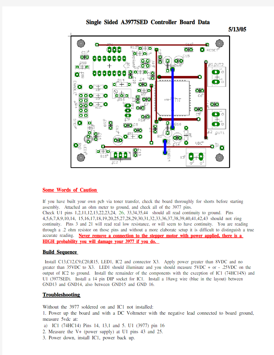
Single Sided A3977SED Controller Board Data
5/13/05
Some Words of Caution
If you have built your own pcb via toner transfer, check the board thoroughly for shorts before starting assembly. Attached an ohm meter to ground, and check all of the 3977 pins.
Check U1 pins 1,2,11,12,13,22,23,24, 26, 33,34,35,44 should all read continuity to ground. Pins
4,5,6,7,8,9,10,14, 15,16,17,18,19,20,25,27,28,29,30,31,32,33,36,37,38,39,40,41,42,43 should not ring continuity. Pins 3 and 21 will read real low resistance, or will seem to have continuity. You are reading through a .2 ohm resistor on those pins and without a more elaborate setup it is difficult to distinguish a true accurate reading. Never remove a connection to the stepper motor with power applied, there is a HIGH probability you will damage your 3977 if you do.
Build Sequence
Install C13,C12,C9,C20,R15, LED1, IC2 and connector X3. Apply power greater than 8VDC and no greater than 35VDC to X3. LED1 should illuminate and you should measure 5VDC + or - .25VDC on the output of IC2 to ground. Install the remainder of the components with the exception of IC1 (74HC14N) and U1 (3977SED). Install a 14 pin DIP socket for IC1. Install a 18awg wire (blue in the layout) between GND13 and GND14, also between GND15 and GND 16.
Troubleshooting
Without the 3977 soldered on and IC1 not installed:
1. Power up the board and with a DC Voltmeter with the negative lead connected to board ground, measure 5vdc at:
a) IC1 (74HC14) Pins 14, 13,1 and 5. U1 (3977) pin 16
2. Measure the V+ (power supply) at U1 pins 43 and 25.
3. Power down, install IC1, power back up.
4. Run the74hc14 (IC1) through hi (Greater Than 4vdc) and low (Less Than .7vdc) states by:
a) IC1 pins 13, 5, and 1 should be hi, IC1 pins 2,3,6,9,12 and 11 should be low, and IC1 pins 10,
4 and 8 should be hi (GT 4vdc). Also 3977 pins 41 and 31 should be high.
b). Leaving power on, jumper pad ENABLE to ground, 3977 pin 41 should now be low
c) Move the jumper pad Step to ground, 3977 pin 31 should go low when the step pad is grounded and should go hi when you remove the jumper.
Now you may install U1 the 3977. (Make sure you’ve disconnected the board from the power source.
JP4 Inputs
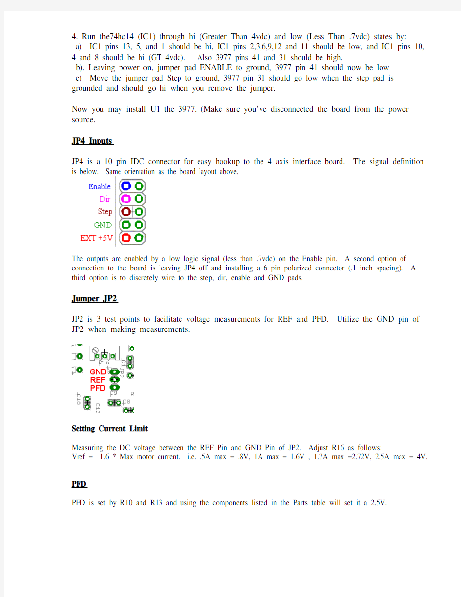
JP4 is a 10 pin IDC connector for easy hookup to the 4 axis interface board. The signal definition is below. Same orientation as the board layout above.
The outputs are enabled by a low logic signal (less than .7vdc) on the Enable pin. A second option of connection to the board is leaving JP4 off and installing a 6 pin polarized connector (.1 inch spacing). A third option is to discretely wire to the step, dir, enable and GND pads.
Jumper JP2
JP2 is 3 test points to facilitate voltage measurements for REF and PFD. Utilize the GND pin of JP2 when making measurements.
Setting Current Limit
Measuring the DC voltage between the REF Pin and GND Pin of JP2. Adjust R16 as follows:
Vref = 1.6 * Max motor current. i.e. .5A max = .8V, 1A max = 1.6V , 1.7A max =2.72V, 2.5A max = 4V. PFD
PFD is set by R10 and R13 and using the components listed in the Parts table will set it a 2.5V.
Jumpers for Micro-Stepping JP3
Jumper in = L, jumper out = H i.e. for full steps both MS1 and MS2 need to be installed. Jumper JP1
JP1 is used to reverse motor direction if the software used does not have the capability to set jumper direction. JP1 must have a jumper from the center post to an adjacent post.
OR
Using the board
The board was designed with a high noise immunity environment in mind. Switching heavy currents and inductive loads are prone to noise. The A3977 driver chip is a chopper, in that it turns the outputs of the driving bridge on and off tens of thousands of times a second. The opportunity for electrical noise is a concern. For that very reason, IC1 is utilized to provide excellent noise rejection. There are two options for IC1. Either a 40106 or 74HC14 Schmitt Trigger Inverter can be installed. The 40106 is older slower technology is preferred for the best noise immunity, but can’t be relied to be driven directly by a PC’s parallel port. If driving from a PC parallel port with no active conditioning logic, a 74HC14 must be used. Software Setup
The step signal has a simple RC filter on it, as do the direction and enable signals. Minimum pulse width for the step pulse is 10us. Maximum step frequency is 40khz. Most steppers torque really drop above 1khz at full step, or 8khz if your using the 1/8th step mode.
Parts
Schematic