A DATA MODELLING FRAMEWORK AND MAPPING MECHANISM TO INCORPORATE CONVENTIONAL CAD SYSTEMS IN
A DATA MODELLING FRAMEWORK AND MAPPING MECHANISM TO INCORPORATE CONVENTIONAL CAD SYSTEMS INTO AN INTEGRATED DESIGN ENVIRONMENT
I. KIM and T. LIEBICH1
ABSTRACT: An Integrated Design Environment facilitates co-operation between different disciplines. The paper investigates the data modelling framework,
distinguishes between homogeneous and heterogeneous model worlds, discusses the
formal mapping mechanisms available to establish a heterogeneous model world, and
introduces a way to incorporate CAD systems into IDE. A prototype IDE has been
developed to prove these methods. The ID'EST prototype comprises its own core data
model, different schemata to cope with several design views, a data management
system to connect all applications seamlessly, and interfaces to incorporate
external CAD systems. A prototype architectural data model has been defined, that
includes core data model and aspect models for enclosure system and spatial system,
and enables semantically meaningful descriptions of buildings. ID'EST uses an
object-oriented database system to store and retrieve project data, that also
supports design versions. The data management system provides consistent and
straightforward mechanisms for controlling the data representation through
interconnected modules.
Key words: Integrated Design Environment, STEP, data modelling, mapping mechanism, object-oriented database
1.INTRODUCTION
The vision of Integrated Design Environments promises collaborative support for the multi-disciplinary nature of the building design process. IDE should enable design teams to efficiently co-operate within a virtual design office, and to easily predict the performance of buildings in order to improve the quality of design. Therefore IDE has to accommodate the multiple views of design disciplines and, vice versa, to support the generation of multiple design representations. Building design and evaluation tools have to work inter-operably via IDE, that controls their consistency.
The structure of an IDE is inherently complex because integration limits the amount of data to be processed, whereas the data structure should be flexible enough to satisfy the diverse foci of the views required in actual design (Fenves et al., 1990). Therefore, the modular structure is an essential requirement. An IDE basically relies on a core data model and different specific partial models, often being structured according to product model definition of its domain. A homogeneous model world, however, where all partial models use the same set of integrated resources is hardly to be achieved in a domain, such as building and construction.
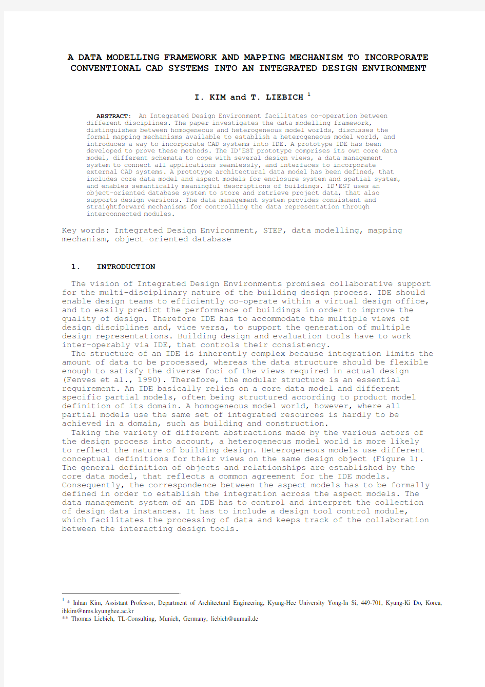
Taking the variety of different abstractions made by the various actors of the design process into account, a heterogeneous model world is more likely to reflect the nature of building design. Heterogeneous models use different conceptual definitions for their views on the same design object (Figure 1). The general definition of objects and relationships are established by the core data model, that reflects a common agreement for the IDE models. Consequently, the correspondence between the aspect models has to be formally defined in order to establish the integration across the aspect models. The data management system of an IDE has to control and interpret the collection of design data instances. It has to include a design tool control module, which facilitates the processing of data and keeps track of the collaboration between the interacting design tools.
1* Inhan Kim, Assistant Professor, Department of Architectural Engineering, Kyung-Hee University Yong-In Si, 449-701, Kyung-Ki Do, Korea, ihkim@nms.kyunghee.ac.kr
** Thomas Liebich, TL-Consulting, Munich, Germany, liebich@uumail.de
Figure 1: Different conceptualisations of physically identical design
objects (Junge, R. and Liebich, T., 1995a)
In this paper, prototypical IDE system, ID'EST, is proposed. Conventional CAD systems can be integrated into ID’EST, if they are able to map data from the aspect models into their own data structure, and vice versa, on a high semantic level. The inherent methods of classifying data in CAD, layers, macros and attached attributes, have been used to retrieve product data from CAD data files. The usability of conventional CAD systems as data instantiation tools for IDE has been proved and a path has been shown, by which existing tools can be integrated into new technology solutions. An existing building has been used to test the integration capability of the implemented system. The results of the example's data classification and projection are documented.
2.THE ROLE OF DATA MODELLING IN IDE
There is now a broad consensus that a conceptual or more precisely a product model is the key to intelligent data exchange and collaboration between different applications. It is particularly the case that the development in relation to ISO-STEP standardisation efforts pushes the process ahead, as it provides appropriate methods, languages, and standardised resources, as well as it encourages the production of necessary tools.
The principles of product modelling are assumed to be known (Gielingh, W., 1988, Junge, R. and Liebich, T., 1995, Eastman, C., 1998), thus the discussion is now focused on the different ways being proposed to model a complex universe of discourse. The domain of building and construction is a excellent example of this kind of complexity, as
-It includes several disciplines with very different views on the elements of buildings,
-It copes with many design, construction and maintenance stages during the life cycle,
-It deals mainly with one-of-a-kind products,
-It establishes several and varying relationships among the participants, and
-It depends heavily on collaboration among the actors of independent organisations.
The product data model is considered as a main prerequisite of IDE, as it is grouped around the abstract definition of a design object rather than its geometric form. There are, however, several ways being proposed to proceed the modelling work in a large and diverse application domain.
a)The first approach in defining one global data model that includes all aspects of any element of buildings has to fail. It seems impossible to deal with the whole universe in a single model and to derive the entire spectrum of views from it.
b)The second approach tries to establish an integrated data model, being structured according to different modelling layers. The layered structure of the STEP model world(STEP 1989-99) follows this approach, since the outermost level of Application Protocols has to use and to specialise only constructs being already modelled within the inner layers of generic and integrated resources. This architecture certainly allows for semantically rich data exchange, but does it also enable flexible integration. A more modular variation of the principle of layered models is the core model approach as followed by the International Alliance for Interoperability, IAI, for the definition of the Industry Foundation Classes, IFC, (IAI, 1996-99). Within IFC, there is a clear distinction between the resource part definition which are later utilised by entity definitions for the definition of their properties, and the kernel part, which provides the first layers within the entity hierarchy.
c)This third approach tries to establish a more flexible structure of loosely integrated aspect models. The several aspect models, each dealings with a specific view of design disciplines, are relative independently defined. They all rely on the common agreement of basic modelling constructs described within the core data models, that preserves the minimum of necessary commonality. That includes the root objects and basic hierarchies of product items, relationships between them, and the systems in which the product items play a role. The aspect models then focus on views, specified according to the needs of design disciplines and life cycle stages. In order to establish this heterogeneous model world, the correspondence between the diverse models has to be defined at the same high conceptual level, as the core and aspect models themselves.
This understanding has led to many research efforts, seeking for formal methods to describe the correspondences between heterogeneous models, in order to utilise the communication within the integrated design environment (Liebich, T., Amor, R. and Verhoef, M, 1995). Formally specifying a mapping mechanism allows the developer to determine the conversion of all required data between the data models. With a mapping defined, it is then possible for a mapping implementation to extract data from a source model for a target model and, additionally, to move data back and guarantee the consistency of the two models in respect to each other (Figure 2).
Figure 2: Mapping specification on modelling and implementation level
(Liebich, T., Amor, R. and Verhoef, M, 1995) Mapping methods are not only applicable to the common integrated environment layout, where several application tools are grouped around a central integrated model. Even for a loose integration without any established integrated model or for the exchange of information by request (Genesereth, M.G. and Fikes, R.E., 1992), mapping can still work as the backbone of the integration. A third field of integration occurs with the requirement to update an integrated model to accommodate the needs of more advanced design tools. Then, mapping provides a mechanism to denote how to propagate data back and forth between older and newer versions of an integrated model (Amor,
R.W., Hosking, J., 1995). A forth and specific field to apply mappings is the CAD integration. Not all principles of the formal mapping specification are applicable here, as the CAD data structure does not follow the principles of product models. The paper will discuss this aspect later.
3.THE ROLE OF CAD IN IDE
CAD systems are treated as one of the several computer-based design tools acting around an IDE. Their specific usage relates to the instantiation process, as they are mainly used to create design instances, which now have to conform to the semantic level of the IDE data models. The new generation of proposed object-oriented CAD systems will certainly be able to provide those design instances (Junge, R. and Liebich, T., 1995b), in the meantime, however, conventional CAD systems can be used through special conventions.
4.SHORTCOMINGS OF CONVENTIONAL CAD SYSTEMS
Conventional CAD systems have inherent bottlenecks, which diminish possible achievements for architectural practices. First, almost all of the conventional CAD systems rely on a pure geometric data model. All non-geometric information about objects of architectural interest has to be attached to these geometric entities. This restricts the ability to describe semantically dependent relationships. Second, the data exchange remains restricted, since it is based on a fairly low semantic level of a document-based exchange of information, such as geometric representation in DXF or IGES, rather than on a high semantic level of a model-based exchange. In consequence, the integration of different design tools for building and construction is still very limited. Thus, different information about the same building object, such as a wall, (e.g., drawing symbols in CAAD systems, cost calculations in spreadsheet programs, tender documents in word processors, and results of compliance checks in simulation tools) cannot be exchanged between the different design tools. CAD systems fail to provide an integrative role due to deficiencies in their underlying database.
4.1Use Of The Inherent Structure Of CAD
In IDE, conventional CAD systems can be used as data instantiation and modification tools with special conventions and some restrictions. CAD systems are able to create the geometrical representation of building objects, and allow additional semantic information as needed for input into the data model. Therefore their inherent structure of classifying data has to be used. Methods of structuring CAD data are:
a) layers
Layers are mainly used to control visibility. In addition they offer the possibility to group sets of data, e.g., all load-bearing walls of ground floor. Many CAD systems still restrict the use of layers so that any entity are only permitted to be assigned to one particular layer.
b) macros (e.g., blocks or parameterised macros)
Macros can be used to label and control all geometric entities that are representations of one building element. Thus, they offer grouping mechanisms on instance level, necessary to maintain unique identifiers for the bi-directional exchange of meaningful descriptions of building elements.
c) attached attributes (e.g., extended entity data)
Attached attributes are mainly used to store non-geometrical information on entities or macros. Examples are the material, the building code, optional explanations, etc.
Those structures have to be used in a standardised manner to allow for the establishment of a semantically rich data exchange. Naming conventions
labelling layers and macros provide such a method to enable the extraction of appropriately structured CAD data for IDE. Some restrictions still remain, since semantic and mainly bi-directional relationships can not be sufficiently expressed in conventional CAD. The support of a beam on a footing is a relationship having its own attributes, e.g., the type (free or restraint) and the bearing pressure. Their expressions in extended entity data sets do not have the power of the corresponding IDE data model constructs, and they are hard to achieve and to manage.
5.STRUCTURE OF ID'EST
The prototypical implementation of an Integrated Design Environment using STep methodology, ID'EST, was carried out to prove the ideas of product data modelling and database implementation, of concepts for data management and CAD integration. ID'EST is an object-oriented design environment that is partitioned into smaller, more manageable pieces in order to be easily maintained. This structure is based on the decomposition criterion known as information hiding, which allows system details that are likely to change independently to be secrets of individual modules. The detailed data management issues have been discussed in the previous research (Kim, I., Liebich, T., and Maver, T., 1997). ID'EST comprises a core data model, a data management system and a set of computer-based design tools:
a) The suggested core data model provides semantically meaningful descriptions of buildings. By means of the core data model, integrated design tool could represent and exchange design information at a semantic level. In consequence, the data model reduces potential misunderstandings and communication problems among the multiple disciplines of architectural design.
b) The data management system organises the structure of the design data to keep the design consistent throughout the design process, and forms the framework in which various building design tools can be seamlessly built. Accordingly, it has to depend on the core data model.
c) Computer based design tools assist designers in creating and evaluating the design artefact and in validating its correctness. These tools are treated as task-related editors of the instantiated data model. They receive all relevant data from the instantiated data model, map them into their own separate data structure, and send the modified data back to the model, in order to maintain. Only private data, which are unlikely to be used by other modules, are permanently stored within the individual databases of the design tools.
5.1Prototype Architecture Data Model
ID'EST comprises the Prototype Architectural Data Model, PADM, developed according to the methodology of STEP. PADM defines the structure of the core data model, as well as the syntax of the exchange format. The design tools, which are connected to ID'EST, communicate on the basis of a STEP physical file, the common exchange format of STEP, and a database in O2 (O2 Technology, 1994a) [1].
The authors had been aware of the ongoing international product data modelling initiatives within the building and construction sector. In order to test the functionality of the ID’EST prototype and to experience the whole development cycle needed to define such a system, the decision was made to develop an own and limited-in-scope PADM.
Three major initiatives are currently active to develop product data models for the establishment of exchange protocols within the building and construction sector:
-The Industry Foundation Classes, defined by the IAI, with the mission “to provide a universal basis for process improvement and information sharing in the construction and facilities management industries.” (IAI 1996-99)
-The CIMsteel model, defined by the CIMsteel consortium to enable the seamless data exchange for constructional steelwork (CIMsteel 1997) -The AP225, define by the ISO TC184/SC4/WG3, the building and construction subgroup of STEP for the data exchange of building elements and spaces using explicit shape representation (ISO DIS 10303-225, 1998)
All schemata representing PADM make use of integrated resources following the STEP methodology. Therefore a subset of the generic resources for topology, geometry and geometric-model (ISO DIS 10303-42, 1993) has been defined as application integrated resources. Development during analysis has been performed using EXPRESS-G (ISO IS 10303-11, 1994a). Two main layers, each consisting of several schemata, have been defined (Figure 3): -The layer of building and construction comprises the schemata building_project and building_system,
-The layer of specific building systems comprises the schemata enclosure_system and spatial_system.
Figure 3: Schema level diagram of ID'EST
During the second phase of design more detailed specifications, such as constraints, functions, and rules, have been added to the model. The graphical notation has to be mapped into a textual form. EXPRESS could be characterised as an object-flavoured specification language and offers the functionality to include these specifications, although there are still some restrictions. In particular, EXPRESS does not support the definition of behavioural aspects of objects, and in this sense it does not provide all features of the object-oriented paradigm. The design model also takes some implementation requirements into consideration.
Figure 4: Data instances in ID'EST
During the third phase of implementation the EXPRESS definition was mapped into an application form. The processing tools, developed at NIST[2] were used during the development process of ID'EST. The layered data model specifies all entity types that represent objects and relationships within the model. Based on this specification, the data instantiation module allows the definition and the exchange of unique entity instances (Figure 4). In consequence, every time the data model has changed, the data instantiation module has to be recompiled.
6.DATA INSTANTIATION MODULE
The data instantiation module creates, edits or views information that is in the instantiation model. The use of an object-oriented database system to directly access data together with the STEP physical file to exchange data in a batch-wise manner provides the way to control and store massive library data, multi-media information and non-graphical information related to a design project.
The main objective of this instantiation module is to provide an instance manipulation environment for the semantically structured entities defined in PADM. An instantiation module should also provide a mechanism to input data being created by an external tool. In ID'EST, a conventional CAD is used to instantiate entities. In this case, in order to import data to the project database, it is necessary to have an accessory tool to convert the external CAD tool data format to the STEP physical file format.
6.1CAD Integration In ID'EST
The creation of building design instances is normally done using conventional CAD systems for the input of geometry. Beside the geometrical representation, more semantic information is needed to extract data for input into the instantiation model. Therefore, the inherent structure of CAD systems plays a key role in enabling the extraction of appropriate data. Naming convention gives the opportunity to map this implicit information into the object-oriented data representation being used in ID'EST.
Within ID'EST AutoCAD was chosen as the particular CAD system and the AIA layer guide (Schley, M.K., 1990) as the main naming convention. There are other CAD layer guides and standards available and in use, e.g. the British Standard BS1192 Part 5:1998 within the United Kingdom, and the international layer standard ISO 13567 (ISO 13567, 1997). In order to maintain consistency between building elements within the data instantiation module and their appropriate CAD representation, the macro structure was intensively used to instantiate unique instances of building elements within the external CAD package. In addition the layer system was used for major grouping, e.g., all building elements within a specific floor level. Each macro in the external CAD file is further defined by attached attributes, describing properties, such as material, building code, price, etc. To import such a structured CAD data file into ID'EST a STEP/DXF interface had to be built.
6.2The STEP/DXF Interface
The STEP/DXF interface, which was developed as a part of the proposed environment, enables the reading of DXF file and translates it into STEP physical file according to the given aspect model. The converter of the STEP/DXF interface incorporates several mechanisms to map structured CAD data into the relevant structure of the data model:
-Mapping code for geometric entities
-Mapping tables for entity type information
-Mapping rules for non-geometric attributes
This element of the STEP/DXF interface is faced with converting the geometric entities representing a building element in CAD into an entity data type for the “has_representation” attribute, which is part of the entity definition of all building elements, as an result of the core data model
agreement. This mapping part includes one-to-one mappings as well as one-to-many mappings. The mapping of geometric entities follows an early binding philosophy, i.e., the converter has to be modified and recompiled whenever the internal structure of either the CAD data format or the schema definitions of geometry or topology within the product model changes. This is, however, an acceptable approach, as the definitions of geometric items are unlikely to be frequently changed.
In order to facilitate a semantically meaningful data exchange between CAD and ID'EST the geometric entities in CAD have to be characterised as representation of building elements. Therefore the macro and layer structure is used in connection with the AIA naming convention. According to the AIA layer guideline, a layer name using the short format has the principle form xyyzz-zz, where x is the major group, representing the different disciplines (e.g., A = architecture, S = structural engineering), yy is the minor group, designating construction systems (e.g., wa = wall, co = column, cl = ceiling), and zz is an user-defined minor group. The same convention was adopted for labelling macros. In order to map the building element macro definitions into specific entity type instances DXF/STEP interface makes use of user defined mapping tables (Figure 5). These mapping tables are read during runtime. They follow a late binding philosophy, since their definitions could be sent together with the physical file. Thus other naming conventions can be easily adopted within ID'EST.
Figure 5: CAD macro structure and mapping table Non-geometric information, usually stored in attached attributes is also converted as. Contrary to the fixed structure of geometric entities in CAD and to the standardised naming conventions for layer and macros, there is no standard by which attributes may be specified. Thus a more flexible approach to define the mapping between attributes in CAD and entities or entity attributes in ID'EST is required. The final aim is to create a universal mapping language to define rules, which control the mapping during runtime.
Again there are two kinds of mapping: one-to-one and one-to-many, and for each attribute-to-attribute and attribute-to-entity mapping. In the case of one-to-one, an attached attribute is mapped into a defined data type having the same name or an alias for that name. In the case of one-to-many, an attached attribute is mapped into an attribute pointing to an entity having the same name or an alias for that name and in addition a defined data type to carry the value of that attached attribute (Figure 6). The next figure shows the final output of a STEP physical file according to the PADM (Figure 7).
Attribute mapping is controlled by rules. They have the principle structure of:
attribute::entity.entity_attribute{.entity_attribute}
The rules for the two mapping pairs, as given in Figure 6, are:
description::SELF.description
material::SELF.has_https://www.360docs.net/doc/fe17966926.html,
whereas SELF refers to that entity type, which was found with the help of the mapping table.
Figure 6: Mapping of attached attributes in DXF/STEP interface These rules reflect only a subset of possible and necessary rules usually included in a formal mapping language, since on the left hand side only simple attributes can exist according to the limitation inherent in the conventional CAD database. Similarly, other methods, e.g., allowing for conditional mappings, are not included. If this functionality is needed, a twofold mapping process has to be implemented in the DXF/STEP interface. First, the CAD data is mapped into an external format, structured according to product model definition, and second the mapping is defined between the external format and any of the aspect models, the data should be mapped to.
Recent research and development has concentrated on the definition of such a formal mapping specification (for a list of prototype language development, see: Liebich, T., Amor, R. and Verhoef, M, 1995). Most of the efforts are now combined to develop EXPRESS-X.
Figure 7: Output of the DXF/STEP interface
7.CONTROL OF DESIGN INFORMATION IN ID'EST
To control and interpret the collection of data instances which is in an application form of the generic data model, a data management system has been devised. The data management system is responsible for creating, maintaining and viewing a consistent database of the design description. Consistency checking and constraint propagation is further tasks of this system which consists of several modules, i.e., data instantiation, data classification
and data projection modules (Kim, I., 1995). These modules assist in the processing of data for design tools. There is a tool hierarchy browser which allows the user to control the level of details.
The integrated design database is a prerequisite for creating an integrated environment by which design data can be shared among the different tools of the environment. In ID'EST, to construct the integrated design database which comprises semantically rich design data, both O2 and a STEP physical file are used. These data storage mediums follow the same underlying data structure defined in the PADM definition for the environment. In the environment, O2 is used as the main medium to store massive library data, multi-media design information and non-graphical information of a design project, whereas the STEP physical file is mainly used for data exchange purposes.
With the help of these software support tools, the design data management system organises the design description within each representation, correlates equivalent descriptions across the representations, and attempts to maintain these correspondences as the design incrementally evolves.
7.1Multi-media Design Information
The materials being shared in a design project may include CAD drawings, pictures and videos of design components, documents, spreadsheets, case records and so forth. To improve the designer's understanding of his/her design, computerised evaluations of the design in various aspects are essential nowadays. The use of multi-media allows us to address an important aspect of collaborative design, as it helps a designer to understand the arguments of other members of the design team by providing examples or making reference to previous cases. In ID'EST, multi-media information can be stored as a part of an integrated project database by virtue of the object-oriented database technology which provides the means to maintain this rich set of design information. To control the relationship between the underlying data structure of the instantiated data model and the multi-media information stored in O2, additional referencing methods are implemented in the data management system.
7.2Design Version Management And Concurrent Design Issues
One of the main data controlling requirements of ID'EST is to cope with design versions in such a way that multiple designers can work on various aspects and components of the same design concurrently. There should be some form of management of the design versions of artefacts and their components, and the integration of component versions into versioned design configurations. The handling of the design versions should be realised by communicating changes to parts of the design to other members of the design team and drawing their attention to the effect of these changes on their own current design version of a component.
Figure 8: Evolution of Versioned Object (Kim, I., Carnduff, T., Gray, A.,
and Miles, J., 1995)
Existing CAD representations of building and engineering designs may be encapsulated within database objects, and hence, be given versioning capabilities, which will allow them to contribute to version evolution graphs. In structural design this approach can include using approximate formulae to provide updated section sizes or areas of reinforced steel. In a version model, a set of versions of an object is managed by a generic version management approach. This generic version maintains a version evolution history and provides a means of access to each of the object versions in the version set, through a dynamic reference. Versioned objects may also be referenced statically without using the generic version. The design version management system is currently under development by the DESCRIBE team (Kim, I., Carnduff, T., Gray, A., and Miles, J., 1995) using O2 (Figure 8.). Some important concepts of the versioning model are described as follows (O2 Technology, 1994b, O2 Version Manager):
a)Root: When a new version is created and initialised, it corresponds to the creation of a version unit and a first version of it. This first version is the root of the derivation graph.
b)Default Version: Information of a default version is persistently stored and the system always chooses the default version when no other version is explicitly chosen.
c)Class: An instance of the class is a particular version belonging to a version unit that manages the versions of object collection.
d)Linked versions: Different versions of the same version unit are linked together by the derivation graph. All these versions comprise the version unit.
8.DATA CLASSIFICATION MODULE AND DATA PROJECTION MODULE
The data classification module classifies the instances of the instantiated data model according to the selected design disciplines. For instance, architectural, structural, mechanical or any other related disciplines information is elicited necessary for the required projections, such as a ground floor plan for the architectural view, an axonometric of columns for
the structural view or an elevation of mechanical entities for the mechanical view. Figure 9 shows four dynamically generated views of structural entities of the prototype building [3] comprising views of beams, slabs, columns and a combination of all three. The projected views are virtual entities which do not exist as data in its own right.
Figure 9: Dynamic Representations of the Structural Entities for the
Prototype Building
In an ideal integrated design environment, a designer should be able to examine information relating to relevant disciplines that are stored in the project database. By selecting one or more buttons in the Discipline Selection Tool panel, the user can view or edit building data of one or more disciplines at the same time. The Data Grouping Tool enables one to limit the views to the currently selected disciplines. To elicit appropriate information from the project database, the data classification module checks the desired entity types, filters necessary information from the database, and sets special marks on the information to identify that which is necessary. By checking entity types and attributes, the data projection process is executed with possible partial model projection and possible re-execution of the data classification process. With the help of the provided display depth control mechanism, several different levels of semantic structures can be investigated. For example, to generate the ground floor plan of the prototype building view dynamically, only data that is defined as the "architectural entities" will be searched during the first stage. During the next stage, with proper projections including selected inheritances, data segregation, and geometric transformations, a certain amount of information for the required plan view is generated. In this case, re-entering of higher level data abstraction is necessary to obtain a section view of necessary columns and their positions.
As a result of the data classification and projection process, an OBJ data file can be generated. The OBJ file is a projected file of the instantiated data model and has the ability to store semantic as well as syntactic
information since it is possible to have structured entities in the file. The display setting can be controlled by the several levels of control module through a well designed interface handler, as the interface system allows selection of desired entities from the instantiated data model. For example, several representations of the building can be generated simultaneously and information relating to which can be accessed and changed from any of the representation windows. Alteration of information affects the non-redundant project database. Therefore, all other representations of the building will be propagated and updated accordingly as the representations of the building are the result of both the data classification and projection process which manipulate the project database.
9.CONCLUSIONS
The authors argue that the human designer should have all the flexibility possible to facilitate his or her work and full responsibility for the project in any design system. The designer should receive all possible support for the crucial parts of the design work, such as collaboration and consistency. The suggested design environment should lead the way to the "ideal CAAD environment" a designer might want to use in future.
ID'EST shows the possibility of supporting a designer's navigation through the database of design artefacts; co-operative working between the different disciplines of building design and construction; and interdisciplinary sharing of data and knowledge among project participants. It is also proved that ID'EST could generate dynamic views of representative entities from the non-redundant project database of the prototype building and that each entity in the generated views can be edited. When the edited entities are changed, all relevant data is propagated accordingly. Various design and evaluation tools can now access data from ID'EST, thus the behaviour of the design artefact will be more predictable.
ID'EST provides the way to connect object oriented database systems with conventional CAD systems under a common conceptual foundation which helps to control semantically rich design information more efficiently. Mapping specifications, in the general scope of model mapping as well in the more narrow scope of CAD integration, are certainly a way to allow for the integration of heterogeneous models. The CAD integration shows a smooth integration path for the intermediate time. Until the new generation of object-oriented CAD systems for the ideal environment is available, conventional CAD systems can be used as data instantiation tools with special conventions. To conclude, the authors argue that the design environment shows the possibility of a seamless and continuous working environment for architects from the initial data modelling process to the final design solution.
REFERENCES
Amor, R.W., Hosking, J., 1995. Mappings: the glue in an integrated system. In Scherer, R.J., Product and Process Modelling in the Building Industry,
Balkema, Rotterdam, pp. 117-124
CIMsteel, 1997, homepage.
https://www.360docs.net/doc/fe17966926.html,/civil/research/cae/cimsteel/cimsteel.htm
Clark, S.N., 1993, An Introduction to the NIST PDES Tool Kit. NISTIR 4336, National Institute of Standards and Technology, USA
Eastman, C.M., 1998, Building Product Models; Computer Environments
Supporting Design & Construction, ISBN 0-8493-0259-5
Fenves, S.J., Flemming, U., Hendrickson, C., Maher, M.L. and Schmitt, G., 1990, Integrated software environment for building design and construction. Computer-aided Design 22, pp. 27-36
Genesereth, M.G. and Fikes, R.E., 1992. Knowledge Interchange Format Version 3.0 Reference Manual. Computer Science Department, Stanford University, CA
Gielingh, W., 1988, General AEC Reference Model. Proceedings of CIB W74 + W78 Seminar, Lund Sweden, pp. 165-178
IAI, International Alliance for Interoperability, 1996-99,
https://www.360docs.net/doc/fe17966926.html,
ISO IS 10303-21, 1994, STEP Part 21: Clear text encoding of the exchange structure. ISO TC184/SC4/WG5
ISO IS 10303-42, 1994, STEP Part 42: Geometric and Topological
Representation. ISO TC184/SC4/WG3
ISO IS 10303-11, 1994, STEP Part 11: EXPRESS Language Reference Manual. ISO TC184/SC4/WG5
ISO, DIS 10303-225, 1998. STEP Part 225: Building Elements using Explicit Shape Representation. TC184/SC4/WG3 Project Draft
ISO 13567, 1997. Technical Product Documentation; Organisation and Naming of Layers for CAD
Junge, R. and Liebich, T., 1995a. New Generation CAD in an Integrated Design Environment: a Path towards Multi-Agent Collaboration, to be published in: Tan, M. (ed.), CAAD futures ‘95, Singapore
Junge, R. and Liebich, T., 1995b. Product modelling for applications: Models for next generation CAAD. In Pahl, P.J., Werner, H. (eds), Computing in Civil and Building Engineering, Balkema, Rotterdam, pp. 309-316
Kim, I., Liebich, T., and Maver, T., Managing design data in an integrated CAAD environment: a product model approach, Journal of Automation in Construction, Vol. 7, NO 1, Elsevier Publisher, ISSN 0926-5805, 1997
Kim, I., 1995, Design tools integration in an integrated design environment. In Kolarevic, B. and Kalisperis, L. (eds), Computing in Design: enabling, capturing and sharing ideas, ACADIA '95 Conference, Seattle, US, pp 72-95 Kim, I., Carnduff, T., Gray, A., and Miles, J., 1995, Object-oriented design system to support concurrent reuse of building and engineering design. to be published in Murphy, J., editor, The Second International Conference on
Object-oriented Information Systems, OOIS'95, Dublin, Ireland
Liebich, T., 1994, Managing Design Data: Including CAD in Integrated Environments In Scherer, R.J., Product and Process Modelling in the Building Industry, Balkema, Rotterdam, pp. 11-18
Liebich, T., Amor, R. and Verhoef, M, 1995, Survey of Mapping Methods
available within the Product Modelling Arena, EXPRESS User Group Conference, Grenoble, France
O2 Technology, 1994a, O2 Reference Manual. O2 Technology Ltd., Horsham, UK
O2 Technology, 1994b, O2 Version Manager. O2 Technology Ltd., Horsham, U.K.
Sauder, D.A., 1993, Data probe user's guide. Technical Report, National PDES Testbed Report Series, NISTIR 5141, National Institute of Standards and Technology, USA
Schenck, D., Wilson, P., 1994, Information Modelling the EXPRESS way. Oxford Univ. Press, New York
Schley, M.K., 1990, Cad layer guideline: Recommended designations for architecture, engineering, and facility
management computer-aided design. Technical report, The American Institute of Architects Press, Washington, D.C. STEP 1989-99, ISO 10303 Editing Committee: STEP on one page, https://www.360docs.net/doc/fe17966926.html,/sc5/soap
1 O
2 is a distributed object-oriented database management system which can be interfaced to standard programming languages. In ID'EST, O2 has been used to produce partitioned design databases holding multiple design component versions.
2 This software tool was developed by NIST [National Institute of Standards and Technology] in the U.S.A to provide a functionality for manipulating and maintaining the individual instances and the list of instances of an instantiated data model according to STEP definitions
3 The authors have proved the interplay between the different modules of ID'EST, using an existing building. The Bloomielaw building, a medium-rise office building located alongside the River Clyde in Glasgow, has been used mainly to test the capability of the data management system and the user interface system.