AG9320中文规格书
AG30 用户手册说明书

AG30 USER’S MANUAL30W A T m A n c e A m pw w w.a c o u s t i c a m p l i f i c a t i o n .c o mThree (3) Year Limited WarrantySubject to the limitations set forth below, Acoustic® hereby represents and warrants that the components of this product shall be free from defectsin workmanship and materials, including implied warranties of merchantability or fitness for a particular purpose, subject to normal use and service,for three (3) years to the original owner from the date of purchase.Retailer and manufacturer shall not be liable for damages based upon inconvenience, loss of use of product, loss of time, interrupted operationor commercial loss or any other incidental or consequential damages including but not limited to lost profits, downtime, goodwill, damage to orreplacement of equipment and property, and any costs of recovering, reprogramming, or reproducing any program or data stored in equipmentthat is used with Acoustic ® products. This guarantee gives you specific legal rights. You may have other legal rights which vary from stateto state. Some states do not allow limitations on how long an implied warranty lasts, so the above limitation may not apply to you.AcousticP .O. Box 5111Thousand Oaks, CA 91359-5111All trademarks and registered trademarks mentioned herein are recognized as the property of their respective holders.0804-8107.02FCC Statements1. C aution: Changes or modifications to this unit not expressly approved by the party responsible for compliance could void the user’s authority tooperate the equipment.2. N ote: This equipment has been tested and found to comply with the limits for a Class B digital device, pursuant to Part 15 of the FCC Rules. Theselimits are designed to provide reasonable protection against harmful interference in a residential installation. This equipment generates, uses,and can radiate radio frequency energy and, if not installed and used in accordance with the instructions, may cause harmful interference to radiocommunications. However, there is no guarantee that interference will not occur in a particular installation. If this equipment does cause harmfulinterference to radio or television reception, which can be determined by turning the equipment off and on, the user is encouraged to try to correctthe interference by one or more of the following measures:•Reorient or relocate the receiving antenna.•Increase the separation between the equipment and receiver.•Connect the equipment into an outlet on a circuit different from that to which the receiver is connected.•Consult the dealer or an experienced radio/TV technician for help.2AG30 USER’S MANUAL30 W A T T A c o u s T i c p e r f o r m A n c e A m pExposurE To high NoisE LEvELs maY CausE pErmaNENT hEariNg Loss. iNdividuaLs varY CoNsidErabLY To3IMpoRtANt SAfEty INStRUctIoNS93 95 110operating and maintenance (servicing) instructions in the literatureApparatus shall not be exposed to dripping or splashing. Objects filled with liquids, such as vases, shall not be placed on the apparatus.8. D o not install this product near any heat sources such as radiators, heat registers, stoves or other apparatus (including amplifiers) that produce heat.9. D o not defeat the safety purpose of the polarized or grounding-type plug. A polarized plug has two blades with one wider than the other. A grounding-typeplug has two blades and a third grounding prong. The wide blade or the third prong are provided for your safety. If theprovided plug does not fit into your outlet, consult an electrician for replacement of the obsolete outlet.10. P rotect the power cord from being walked on or pinched, particularly at plugs, convenience receptacles, and the point wherethey exit from the apparatus. Do not break the ground pin of the power supply cord.11. Only use attachments specified by the manufacturer.12. U se only with the cart, stand, tripod, bracket, or table specified by the manufacturer or sold with the apparatus. When a cart is used, exercise caution whenmoving.13. Unplug this apparatus during lightning storms or when unused for a long period of time.14. Care should be taken so that objects do not fall and liquids are not spilled into the unit through the ventilation ports or any other openings.15. Refer all servicing to qualified service personnel. Servicing is required when the apparatus has been damaged in any way.16. WARNING: To reduce the risk of fire or electric shock, do not expose this apparatus to rain or moisture.17. When a mains plug or an appliance coupler is used as the disconnect device, the disconnect device shall remain readily operable.18. An apparatus with CLASS 1 construction shall be connected to a MAINS socket outlet with a protective grounding connection.According to OSHA, any exposure in the above permissible limitscould result in some hearing loss. Hearing protection must beworn when operating this amplification system in order to preventpermanent hearing loss.w w w.a c o u s t i c a m p l i f i c a t i o n .c o m WarraNTY (2)imporTaNT safETY iNsTruCTioNs (3)WELComE (5)our missioN (5)a Word abouT Your amp (5)froNT paNEL (6)CabiNET fEaTurEs (7)spECifiCaTioNs (8)TakiNg CarE of Your NEW ampLifiEr ..............................8 tABLE of coNtENtS4AG30 USER’S MANUAL30W A T T A c o u s T i c p e r f o r m A n c e A m pwELcoME ANd coNGRAtULAtIoNS!Congratulations on your purchase of the AG30 acoustic performance amplifier. Founded as the Acoustic Control Corporation in Van Nuys, California in 1969, Acoustic has been the rig of choice for many legendary touring professionals. Acoustic amp users include some of music’s premier rock, jazz and funk players — and many original Acoustic rigs are still cranking out professional tones on stages world wide.Now you own a piece of the Acoustic legacy — so turn it up and enjoy what pros have known about for decades. Welcome to Acoustic, the Pro’s Tone™.oUR MISSIoNThe Acoustic design philosophy is simple. It’s simple to operate, simple to maintain, and its Fast-Tone™ technology allows you to dial up great sound in an instant. This way of thinking is part of every amp we make. That’s why many legendary musicians have used Acoustic to develop their trademark sounds.If you’re new to Acoustic amps, we encourage you to get in tune with its rich heritage and join the long line of Acoustic users who would never consider playing through anything else.A woRd ABoUt yoUR NEw AMpYour new Acoustic amplifier is designed to sound great with any acoustic instrument. We put a lot of thought and effort into selecting exactly the right components and designing a product that will be easy to adjust so you can quickly find the voice of your instrument and project it beyond your personal performance space.One example is the 8” studio monitor style speaker which has a polypropylene cone speaker with a rubber surround. This produces a very soft, warm, low frequency response. Additionally, the coaxial tweeter provides a chime-like clarity to your high frequencies.No matter what your style of playing or choice of acoustic instrument, you will find that your new amp will capture and project the very best of your musical voice.5w w w.a c o u s t i c a m p l i f i c a t i o n .c o m 6fRoNt pANEL1. Dual combination balanced XLR and 1/4” 2-conductor acoustic instrument inputs. These two inputs maybe used simultaneously and each have their own Volume control. You may plug an acoustic instrumentand/or microphone into either channel.2. Volume control. These controls adjusts the overall loudness of the individual channels of the amplifier.If your acoustic instrument has a preamp, you should set the volume control on your instrument at about half volume. You can then adjust the amplifier volume to your normal playing level and still have room to increase or decrease your volume as needed from the instrument.3. Low frequency control set to boost (15 dB) or cut (-15 dB) frequencies at 80 Hz. Controls the lowestfundamental frequencies to enhance the warmth and deep, full tones of your acoustic instrument.4. Midrange frequency control set to boost (15 dB) or cut (-15 dB) frequencies that you can sweep between500Hz and 1.2kHz. Moving the midrange frequency and either cutting or boosting this frequency willgive you maximum control over the body of your tone. This control can also be useful in eliminatingacoustic feedback. It also allows you to control the definition and voice of your acoustic instrument.5. High control set to boost (15 dB) or cut (-15 dB) frequencies at 10 kHz. Increasing this will enhance theclarity and brightness of your acoustic instrument.6. The Effect level control is used to determine how much of the selected effect is applied to your music.7. Effect Select control allows you to select from one of 16 different effects including reverbs, delays, chorusesand combinations of the above. The 16 effects are detailed in a printed chart on the top panel of the AG30.8. This 3-conductor 1/8” aux input jack will allow you to plug in a CD, MP3 player or any other source so youcan play along. To control the volume of this input, adjust the output volume of the device.9. This 1/8” 3-conductor jack is for plugging in headphones. When used, it will disconnect the internal speaker.10. The Line Out jack will provide an unbalanced, line-level signal which can be sent directly to a soundboard, live mixing console, a self-powered speaker or even another amplifier. You should always use a1/4” shielded cable (standard guitar cable) when using this output to connect to another device.11. Power LED. This light will illuminate with a soft blue color when the amp is turned on andready to play.AG30 USER’S MANUAL30 W A T T A c o u s T i c p e r f o r m A n c e A m p 75cABINEt fEAtURES Heavy-Weight cloth Grill 1Heavy-Duty 8” coax studio – monitor style speaker 2Angled monitor style cabinet projects sound upwards3rugged & comfortable Handle4easy to read control panel5protective, Long-Lasting covering 623146w w w.a c o u s t i c a m p l i f i c a t i o n .c o m 8SpEcIfIcAtIoNSModel AG30LocATion• To avoid deformation, discoloration, or more serious damage, do not expose the unit to direct sunlight, high temperature sources, or excessive humidity.poWer suppLY• Turn the power switch off when the AG30 is not in use.• The amplifier (main pug) should be unplugged from the AC outlet if the AG30 will not be used for an extended period of time.• Avoid plugging the amplifier (main plug) into an AC outlet that is also powering high consumption appliances such as electric heaters or televisions. Also avoid using multi-plug adapters since these can reduce sound quality, cause operation errors, and result in possible damage.• To avoid damage, turn off the AG30 power switch and all related devices prior to connecting or disconnecting cables.HAnDLinG AnD TrAnsporT• Never apply excessive force to any parts.• Unplug cables by gripping plugs firmly. Do not pull on cables.• Physical shocks caused by dropping or bumping can result in serious damage.cLeAninG• Clean with a dry, soft cloth.• A slightly damp cloth may be used to remove stubborn grime and dirt.• Never use cleaners such as alcohol or thinner.eLecTricAL inTerference• The AG30 contains electronic circuitry that may cause interference if placed too close to radio or television receivers. If this occurs, move the AG30 further away from the affected equipment.serVice AnD moDificATion• There are no user serviceable parts in the AG30.• Do not attempt to open the AG30 or make any change to circuits or parts. This will void the warranty.tAkING cARE of yoUR NEw AMpLIfIER。
SPS-9380G中文资料

Optoway SPS-9380G**********************************************************************************************************************************************************************************************************************************************************************************************************************************************OPTOWAY TECHNOLOGY INC. No .38, Kuang Fu S. Road, Hu Kou, Hsin Chu Industrial Park, Hsin Chu, Taiwan 303Tel: 886-3-5979798 Fax: 886-3-597973712/1/2005 V2.0 1SPS-9380G / SPS-9380BG (RoHS Compliant)3.3V / 1550 nm / 2.5 Gbps SFP LC SINGLE-MODE TRANSCEIVER**********************************************************************************************************************************************************************FEATURESl Hot-Pluggable SFP Footprint LC Optical Transceiver l Small Form-Factor Pluggable (SFP) MSA compatible l Compliant with SONET OC-48 (LR-2) / SDH STM-16 (L-16.2)l Compliant with Fibre Channel 1x/2x SM-LC-L FC-PI l Compliant with IEEE 802.3z 1000BASE l 1550 nm DFB LD Transmitter l APD High Sensitivity Receiver l 26 dB Power Budget at Leastl AC/AC Coupling according to MSA l Single +3.3 V Power Supply l RoHS Compliantl 0 to 70o C Operation : SPS-9380G l -10 to 85o C Operation : SPS-9380BGl Class 1 Laser International Safety Standard IEC-60825 CompliantAPPLICATIONSl ATM Switches and Routersl SONET / SDH Switch Infrastructure l XDSL Applications l Metro Edge SwitchingDESCRIPTIONThe SPS-9380G series single mode transceivers is small form factor pluggable module for bi-directional serial optical data communications such as SONET OC-48 / SDH STM-16, Gigabit Ethernet 1000BASE-LX and Fibre Channel 1x/2x SM-LC-L FC-PI. It is with the SFP 20-pin connector to allow hot plug capability. This module is designed for single mode fiber and operates at a nominal wavelength of 1550 nm. A guaranteed minimum optical link budget of 26 dB is offered which can correspond to a link distance of over 80 km (assuming worst case fiber loss of 0.25 dB/km). The transmitter section uses a multiple quantum well 1550 nm DFB laser and is a class 1 laser compliant according to International Safety Standard IEC-60825. The receiver section uses an integrated InGaAs detector preamplifier (IDP) mounted in an optical header and a limiting post-amplifier IC.LASER SAFETYThis single mode transceiver is a Class 1 laser product. It complies with IEC-60825 and FDA 21 CFR 1040.10 and 1040.11. The transceiver must be operated within the specified temperature and voltage limits. The optical ports of the module shall be terminated with an optical connector or with a dust plug.ORDER INFORMATIONP/No.Bit Rate (Gb/s) SONET /SDH Distance (km) Wavelength (nm) Package Temp. (o C) TX Power (dBm) RX Sens. (dBm) RoHS Compliant SPS-9380G 2.488 LR-2/L-16.2 80 1550 DFB LC SFP 0 to 70 3 to -2 -28 Yes SPS-9380BG2.488LR-2/L-16.280 1550 DFB LC SFP -10 to 85 3 to -2 -28 YesAbsolute Maximum RatingsParameterSymbol Min Max Units NotesStorage TemperatureTstg -40 85 o COperating Case Temperature Topr 0 -10 70 85 o C SPS-9380G SPS-9380BG Power Supply VoltageVcc-0.53.6VRecommended Operating ConditionsParameterSymbol Min Typ Max Units / NotesPower Supply VoltageVcc 3.13 3.3 3.47 V Operating Case Temperature Topr 0 -10 70 85 oC / SPS-9380G oC / SPS-9380BGPower Supply Current I CC (TX+RX)230 300 mA Data Rate62224882670Mb/s / 1Transmitter Specifications (0o C < Topr < 70o C, 3.13V < Vcc < 3.47V)Parameter Symbol Min Typ Max Units NotesOpticalOptical Transmit Power Po -2 --- 3 dBm 1Output Center Wavelength λ1500 1550 1580 nmOutput Spectrum Width ∆λ--- --- 1 nm -20 dB WidthSide Mode Suppression Ratio SMSR 30 dBExtinction Ratio E R8.2 --- --- dBOutput Eye Compliant with Telecordia GR-253-GORE and ITU-T Recommendation G.957Optical Rise Time t r150 ps 20 % to 80% Values Optical Fall Time t f150 ps 20 % to 80% Values Relative Intensity Noise RIN -120 dB/HzDispersion Penalty 2 dB 2ElectricalData Input Current – Low I IL-350 µAData Input Current – High I IH350 µADifferential Input Voltage V IH - V IL0.5 2.4 V Peak-to-PeakTX Disable Input Voltage – Low T DIS, L0 0.5 V 3TX Disable Input Voltage – High T DIS, H 2.0 Vcc V 3TX Disable Assert Time T ASSERT10 µsTX Disable Deassert Time T DEASSERT 1 msTX Fault Output Voltage -- Low T FaultL0 0.5 V 4TX Fault Output Voltage -- High T FaultH 2.0 Vcc+0.3 V 41. Output power is power coupled into a 9/125 µm single mode fiber.2. Specified at 1600 ps/nm dispersion over G.652/G.654 fiber with center wavelength range of 1500 to 1580 nm.3. There is an internal4.7K to 10K ohm pull-up resistor to VccTX.4. Open collector compatible, 4.7K to 10K ohm pull-up to Vcc (Host Supply Voltage).Receiver Specifications(0o C < Topr < 70o C, 3.13V < Vcc < 3.47V)Parameter Symbol Min Typ Max Units NotesOpticalSensitivity Sens -28 dBm 5,6Maximum Input Power Pin -9 dBm 5,6Signal Detect -- Asserted Pa --- -28 dBm Transition: low to high Signal Detect -- Deasserted Pd -40 --- --- dBm Transition: high to low Signal detect -- Hysteresis 1.0 --- dBWavelength of Operation 1260 --- 1600 nmElectricalDifferential Output Voltage V OH– V OL0.6 2.0 VOutput LOS Voltage -- Low V OL0 0.5 V 7Output LOS Voltage -- High V OH 2.0 Vcc+0.3 V 75. Measured at 2-1 PRBS at BER 1E-10.6. Measured at 27-1 PRBS at BER 1E-12 for 2.125 Gb/s, 1.25Gb/s, and 1.063 Gb/s.7. Open collector compatible, 4.7K to 10K ohm pull-up to Vcc (Host Supply Voltage).**************************************************************************************************************************************************************************** OPTOWAY TECHNOLOGY INC. No.38, Kuang Fu S. Road, Hu Kou, Hsin Chu Industrial Park, Hsin Chu, Taiwan 303****************************************************************************************************************************************************************************OPTOWAY TECHNOLOGY INC. No .38, Kuang Fu S. Road, Hu Kou, Hsin Chu Industrial Park, Hsin Chu, Taiwan 303PINSignal NameDescriptionPINSignal Name Description1 TX GND Transmitter Ground11 RX GND Receiver Ground2 TX Fault Transmitter Fault Indication12 RX DATA OUT- Inverse Receiver Data Out 3 TX Disable Transmitter Disable (Module disables on high or open)13 RX DATA OUT+ Receiver Data Out 4 MOD-DFE2 Modulation Definition 2 – Two wires serial ID Interface14 RX GND Receiver Ground5 MOD-DEF1 Modulation Definition 1 – Two wires serial ID Interface15 Vcc RX Receiver Power – 3.3V ±5% 6 MOD-DEF0 Modulation Definition 0 – Ground in Module16 Vcc TX Transmitter Power – 3.3V ±5% 7 N/C Not Connected 17 TX GNDTransmitter Ground 8 LOS Loss of Signal 18 TX DATA IN+ Transmitter Data In9 RX GND Receiver Ground 19 TX DATA IN- Inverse Transmitter Data In 10RX GNDReceiver Ground20TX GNDTransmitter GroundModule DefinitionModule DefinitionMOD-DEF2 PIN 4 MOD-DEF1 PIN 5 MOD-DEF0 PIN 6 Interpretation by Host 4SDASCLLV-TTL LowSerial module definitionprotocolModule Definition 4 specifies a serial definition protocol. For this definition, upon power up, MOD-DEF(1:2) appear as no connector (NC) and MOD-DEF(0) is TTL LOW. When the host system detects this condition, it activates the serial protocol. The protocol uses the 2-wire serial CMOS E 2PROM protocol of the ATMEL AT24C01A/02/04 family of components.**************************************************************************************************************************************************************************** OPTOWAY TECHNOLOGY INC. No.38, Kuang Fu S. Road, Hu Kou, Hsin Chu Industrial Park, Hsin Chu, Taiwan 303。
AG9300中文规格书
AG9300Type C转VGA转换器2020年1月AG9300 Type 转VGA转换器AG9300修订历史PS:本中文规格书由第三方翻译软件自动翻译,权威信息请以原厂英文版规格书为准。
公开发行2AG9300 Type 转VGA转换器索引I.概述 (5)II.特性 (5)III.设备信息 (6)IV.应用 (6)V.系统框图 (7)VI. 管脚映射和描述 (8)VII.规格明细 (12)i. 绝对最大额定值 (12)ii. 直流特性/工作条件 (12)iii. 交流特性 (13)VIII. 包装和标记规范 (16)公开发行3AG9300 Type 转VGA转换器图目录图1 C型到HDMI加密狗的应用 (6)图2系统框图 (7)图3 AG9300-MBQ引脚映射 (8)图4 AG9300-MCQ引脚映射 (9)图5 AG9300-MBQ包装尺寸 (17)图6 AG9300-MCQ包装尺寸 (18)表格目录表1引脚说明 (11)表2绝对最大额定值 (12)表3数字I/O规范 (11)表4显示端口输入定时 (13)表5显示端口辅助通道I/O规格 (14)表6 USB I/O规格 (15)表7 USB PD规格 (15)公开发行4AG9300 Type 转VGA转换器一、 AG9300概述ALGOLTEK AG9300是一款实现USB Type-C 转VGA数据转换器的单片机解决方案。
支持USB Type-C显示端口交替模式,AG9300可以将视频和音频流从USB Type-C接口传输到VGA端口。
在AG9300中,支持1、2、4通道@1.62Gbps、2.7Gbps、5.4Gbps频率输入的不同配置,VGA支持1200P@60Hz输出。
产品制造商可轻松实现Type-C使用G9300应用程序进行视频转换器转接。
二、 AG9300特性嵌入式16位单片机支持EDID和MCC直通AG9300支持热插拔检测AG9300支持外部SPI闪存固件升级AG9300支持嵌入式HDCP 1.41.2V核心电源和3.3V I/O电源嵌入式5V/1.2V高效稳压器2KV ESD performance 2KV ESD性能AG9300支持下行扩频时钟(SSC)公开发行5AG9300 Type 转VGA转换器三、AG9300设备信息四、AG9300应用程序USB Type-C 转换器USB Type-C扩展坞电视/投影仪Type-C接口公开发行6AG9300 Type 转VGA转换器五、 AG9300系统框图图2系统框图公开发行7AG9300 Type 转VGA转换器六、 AG9300管脚映射和描述图3 AG9300-MBQ引脚映射公开发行8AG9300 Type 转VGA转换器图4AG9300-MCQ引脚映射公开发行9AG9300 Type 转VGA转换器公开发行10AG9300 Type 转VGA转换器表1引脚说明公开发行11AG9300 Type 转VGA转换器七、 AG9300规格i.绝对最大额定值表2绝对最大额定值ii.直流特性/工作条件表3数字I/O规范公开发行12AG9300 Type 转VGA转换器iii.交流特性DisplayPort Main Link AC CharacteristicsTable 4 DisplayPort Input Timing公开发行13AG9300 Type 转VGA转换器DisplayPort AUX-CH AC CharacteristicsTable 5 DisplayPort AUX Channel I/O Specification公开发行14AG9300 Type 转VGA转换器USB PD BMC Receiver Normative RequirementsTable 6 USB I/O SpecificationUSB PD BMC Transmitter Normative RequirementsTable 7 USB PD Specification公开发行15AG9300 Type 转VGA转换器八、 AG9300包装和标记规范Marking标记公开发行16AG9300 Type 转VGA转换器AG9300包装尺寸AG930-MBQ: QFN-48L 6x6mm图5 AG930-MBQ包装尺寸公开发行17AG9300 Type 转VGA转换器AG9300-MCQ: QFN-64L 8x8mm图6 AG9300-MCQ包装尺寸公开发行18。
Algoltek安格产品系列2020

Product P/N Application Product Description/ Resolution ※ Compliant to MHL2.2 and HDMI1.4b ※ Resolution and Frame Rate:- 1080p 60 frame - 3D as 1080p 30 frames in Packed pixel mode ※ Compliant to HDMI1.4b and VESA VSIS TM V1.2 Standard ※ VGA Resolution: 1920X1200@60Hz ※ 3-In to 1-Out Switcher ※ Compliant to HDMI1.4b※ Resolution and Frame Rate:- Support 340 MHz pixel clocks- Compatible with 36-bit deep color※ 3-In to 1-Out SwitcherMHL to HDMI Converter HDMI to VGA Converter HDMI 3:1 Switch AG6111AG6200AG7110Algoltek安格|产品大全|产品选型|产品功能列表※ Compliant to HDMI1.4b ※ Resolution and Frame Rate:- Support 340 MHz pixel clocks - Compatible with 36-bit deep color ※ Compliant to HDMI1.4b ※ Resolution and Frame Rate:- Support 340 MHz pixel clocks - Support 4K2K@30Hz, compatible with 36-bit deep color ※ Embedded 16 bit MCU ※ External SPI flash supported for firmware upgrade ※ Down Spread Spectrum Clock (SSC)supported ※ On-chip HDCP1.4 Key Integrated ※ Support I2S stereo audio interface ※ Embedded 16 bit MCU ※ External SPI flash supported for firmware upgrade ※ Down Spread Spectrum Clock (SSC)supported ※ On-chip HDCP1.4 Key Integrated ※ Support I2S stereo audio interface ※ Embedded 16 bit MCU ※ External SPI flash supported for firmware upgrade ※ Down Spread Spectrum Clock (SSC)supported ※ On-chip HDCP1.4 Key Integrated ※ Support I2S stereo audio interface ※ Type-C DP ALT mode supported ※ Embedded 16 bit MCU ※ External SPI flash supported for firmware upgrade ※ Down Spread Spectrum Clock (SSC)supported ※ On-chip HDCP1.4 Key Integrated ※ Support I2S stereo audio interface ※ Type-C DP ALT mode supported ※ Embedded 16 bit MCU ※ External SPI flash supported for firmware upgrade ※ Down Spread Spectrum Clock (SSC)supported ※ On-chip HDCP1.4 Key Integrated ※ Support I2S stereo audio interface ※ Type-C DP ALT mode supported ※ Embedded 16 bit MCU ※ External SPI flash supported for firmware upgrade AG9320HDMI 3:1 Switch HDMI 1:1ReDriver DP to VGA Converter DP to HDMI Converter DP to HDMI/VGA Converter USB Type-C to VGA Converter USB Type-C to HDMI Converter USB Type-C to HDMI/VGAConverterAG6300AG6310AG6320AG9300AG9310AG7111AG7120※ Down Spread Spectrum Clock (SSC)supported※ On-chip HDCP1.4 Key Integrated ※ Support I2S stereo audio interface AG9320USB Type-C toHDMI/VGAConverter。
AG6200-MCQ中文规格书
AG6200-MCQHDMI转VGA转换器中文数据表V1.3 QQ176490316 TEL136七023 2221变更历史PS:本中文规格书由第三方翻译软件自动翻译,权威信息请以原厂英文版规格书为准。
索引1.特点和功能描述 (2)管脚映射 (2)管脚说明 (3)2.电气特性 (4)直流规范 (5)交流规格 (6)3.包装和标记规范 (6)标记 (6)包装尺寸 (7)4.参考文献 (7)图片列表图1 HDMI到VGA桥接器的应用程序 (1)图2系统框图 (2)图3 48引脚映射 (2)表格列表表1引脚说明 (4)表2正常运行条件 (4)表3直流电源典型电源特性 (5)表4直流规范 (5)表5数字I/O规范 (5)表6 TMDS输入时间 (6)AG6200-MCQ特征将HDMI 1.4b转换为VGAAG6200支持高达1920x1200@60Hz的视频分辨率:AG6200支持热插拔检测内置晶体,无需外挂晶体。
内置5V至1.2V稳压器核心电压1.2V符合HDCP 1.4规范的片上HDCP引擎集成片上HDCP密钥AG6200支持2通道IIS音频接口AG6200支持1080i分辨率AG6200-MCQ封装(QQ176490316 TEL136********)AG6200-MCQ封装尺寸:48-pin QFN,6 mm x 6 mmAG6200-MCQ温度范围(0℃~+85℃)AG6200-MCQ应用电缆适配器扩展底座、扩展坞AG6200-MCQ概述Algoltek AG6200-MCQ芯片是一个HDMI(高清多媒体接口)到VGA桥接芯片。
它将HDMI信号转换为标准VGA信号它可以在适配器、智能电缆等设备中设计图1 HDMI到VGA网桥的应用1、AG6200-MCQ系统框图和功能描述图2系统框图AG6200-MCQ引脚映射图3 48引脚映射AG6200-MCQ管脚说明Tabl表1引脚说明2、AG6200-MCQ电气特性正常工作条件表2正常运行条件直流规范表3直流电源典型电源规格表4直流电源最大供电规范表5数字I/O规交流规格表6 TMDS输入时间3、AG6200-MCQ包装和标记规范AG6200-MCQ标记AG6200-MCQHDMI 转VGA 转换器 11 / 112020-02-08 AG6200-MCQ 包装尺寸QFN48 QFN48注1。
JD Ag Product Line ( Chinese Version )

农具 – 耘耕机
960 悬挂式 2210 牵引式
农具 – 铧式犁
2810 半悬挂式 3710 牵引式 975 沟中水平转向式 995 岸上转向式
农具 – 联合整地机
726 714
农具 – 深松机
512 园盘耙深松联合整地机 2700 覆盖式深松联合整地机 22B 悬挂式身松机 913 V型深松机 915 V型深松机 2100 微耕深松机
喷药机 – 自走式喷药机
6700, 60英尺喷臂 4720, 60、80、 90英尺喷臂 4920, 70、90、120英尺喷臂
喷药机 – 悬挂式和牵引式喷药机
约翰迪尔农机产品
拖拉机 联合收割机 棉花收获机 牧草和青贮设备 农具 播种机 喷药机 物料处理、 割草, 秸秆粉碎, 搬运机械 农业管理解决方案
农具 – 中耕机
856 886
约翰迪尔农机产品
拖拉机 联合收割机 棉花收获机 牧草和青贮设备 农具 播种机 喷药机 物料处理、 割草, 秸秆粉碎, 搬运机械 农业管理解决方案
播种机 – 精量点播机
播种机 – 条播机
1520 悬挂式 1530 V型开沟器式 1535 V型开沟器式 1590 谷物免耕型 1570 秸秆切碎机 450 谷物条播 455 谷物条播
拖拉机 联合收割机 棉花收获机 牧草和青贮设备 农具 播种机 喷药机 物料处理、 割草, 秸秆粉碎, 搬运机械 农业管理解决方案
农具 – 凿型犁
610 悬挂式 2410 牵引式 240 弹齿耙附件
MAXIM MAX9320B 说明书
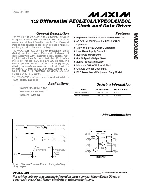
For pricing delivery, and ordering information please contact Maxim/Dallas Direct!at 1-888-629-4642, or visit Maxim’s website at .General DescriptionThe MAX9320B low-skew, 1-to-2 differential driver is designed for clock and data distribution. The input is reproduced at two differential outputs. The differential input can be adapted to accept single-ended inputs by applying an external reference voltage.The MAX9320B features ultra-low propagation delay (208ps), part-to-part skew (20ps), and output-to-output skew (6ps) with 30mA maximum supply current, mak-ing this device ideal for clock distribution. For interfac-ing to differential PECL and LVPECL signals, this device operates over a +3.0V to +5.5V supply range,allowing high-performance clock or data distribution in systems with a nominal 3.3V or 5V supply. For differen-tial ECL and LVECL operation, this device operates from a -3.0V to -5.5V supply.The MAX9320B is offered in industry-standard 8-pin TSSOP and SO packages.ApplicationsPrecision Clock Distribution Low-Jitter Data Repeater Protection SwitchingFeatureso Improved Second Source of the MC10EP11D o +3.0V to +5.5V Differential PECL/LVPECL Operationo -3.0V to -5.5V ECL/LVECL Operation o Low 22mA Supply Current o 20ps Part-to-Part Skew o 6ps Output-to-Output Skew o 208ps Propagation Delay o Minimum 300mV Output at 3GHz o Outputs Low for Open Inputo ESD Protection >2kV (Human Body Model)MAX9320B1:2 Differential PECL/ECL/LVPECL/LVECLClock and Data Driver________________________________________________________________Maxim Integrated Products1Pin Configuration19-2383; Rev 1; 11/03Ordering InformationFigure 1. Differential Transition Time and Propagation Delay Timing DiagramM A X 9320B1:2 Differential PECL/ECL/LVPECL/LVECL Clock and Data Driver 2_______________________________________________________________________________________ABSOLUTE MAXIMUM RATINGSDC ELECTRICAL CHARACTERISTICS(V CC - V EE = 3.0V to 5.5V, outputs loaded with 50Ω±1% to V CC - 2V. Typical values are at V CC - V EE = 5.0V, V IHD = V CC - 1.0V, V ILD = V CC - 1.5V, unless otherwise noted.) (Notes 1, 2, 3)Stresses beyond those listed under “Absolute Maximum Ratings” may cause permanent damage to the device. These are stress ratings only, and functional operation of the device at these or any other conditions beyond those indicated in the operational sections of the specifications is not implied. Exposure to absolute maximum rating conditions for extended periods may affect device reliability.V CC to V EE .............................................................................+6V D or D ....................................................V EE - 0.3V to V CC + 0.3V D or D with the Other Floating.............V CC - 5.0V to V CC + 0.3V D to D .................................................................................±3.0V Continuous Output Current.................................................50mA Surge Output Current........................................................100mA Continuous Output Power Dissipation (T A = +70°C)8-Pin TSSOP(derate 4.5mW/°C above +70°C).................................362mW 8-Pin SO(derate 5.9mW/°C above +70°C).................................471mW Junction-to-Ambient Thermal Resistance in Still Air8-Pin TSSOP............................................................+221°C/W 8-Pin SO...................................................................+170°C/WJunction-to-Ambient Thermal Resistance with 500 LFPM Airflow8-Pin TSSOP............................................................+155°C/W 8-Pin SO.....................................................................+99°C/W Junction-to-Case Thermal Resistance8-Pin TSSOP..............................................................+39°C/W 8-Pin SO.....................................................................+40°C/W Operating Temperature Range ...........................-40°C to +85°C Junction Temperature......................................................+150°C Storage Temperature Range.............................-65°C to +150°C ESD ProtectionHuman Body Model (D, D , Q_, Q_).................................>2kV Soldering Temperature (10s)...........................................+300°CMAX9320B1:2 Differential PECL/ECL/LVPECL/LVECLClock and Data Driver_______________________________________________________________________________________3DC ELECTRICAL CHARACTERISTICS (continued)(V CC - V EE = 3.0V to 5.5V, outputs loaded with 50Ω±1% to V CC - 2V. Typical values are at V CC - V EE = 5.0V, V IHD = V CC - 1.0V, V ILD = V CC - 1.5V, unless otherwise noted.) (Notes 1, 2, 3)AC ELECTRICAL CHARACTERISTICS(V CC - V EE = 3.0V to 5.5V, outputs loaded with 50Ω±1% to V CC - 2V, input frequency ≤1.5GHz, input transition time = 125ps (20% to 80%), V IHD = V EE + 1.2V to V CC , V ILD = V EE to V CC - 0.15V, V IHD - V ILD = 0.15V to 3.0V. Typical values are at V CC - V EE = 5.0V, V IHDTypical Operating Characteristics(V CC = 5V, V EE = 0, input transition time = 125ps (20% to 80%), V IHD = V CC - 1V, V ILD = V CC - 1.5V, f IN = 1.5GHz, outputs loaded with 50Ωto V CC - 2V, T A = +25°C, unless otherwise noted.)Note 3:DC parameters production tested at T A = +25°C. Guaranteed by design and characterization over the full operating temper-ature range.Note 4:All pins open except V CC and V EE .Note 5:Guaranteed by design and characterization. Limits are set at ±6 sigma.Note 6:Measured between outputs of the same part at the signal crossing points for a same-edge transition.Note 7:Measured between outputs of different parts at the signal crossing points under identical conditions for a same-edge transition.Note 8:Device jitter added to the input signal.M A X 9320B1:2 Differential PECL/ECL/LVPECL/LVECL Clock and Data Driver 4_______________________________________________________________________________________AC ELECTRICAL CHARACTERISTICS (continued)(V CC - V EE = 3.0V to 5.5V, outputs loaded with 50Ω±1% to V CC - 2V, input frequency ≤1.5GHz, input transition time = 125ps (20% to 80%), V IHD = V EE + 1.2V to V CC , V ILD = V EE to V CC - 0.15V, V IHD - V ILD = 0.15V to 3.0V. Typical values are at V CC - V EE = 5.0V, V IHD = V CC - 1V, V ILD = V CC - 1.5V, unless otherwise noted.) (Note 5)TRANSITION TIME vs. TEMPERATURETEMPERATURE (°C)T R A N S I T I O N T I M E (p s )603510-1585909510010511080-4085OUTPUT AMPLITUDE, V OH - V OLvs. FREQUENCYM A X 9320B t o c 02FREQUENCY (MHz)O U T P U T A M P L I T U D E (V )300025005001000150020000.10.20.30.40.50.60.70.8003500SUPPLY CURRENT, I EE vs. TEMPERATUREM A X 9320B t o c 01TEMPERATURE (°C)S U P P L Y C U R R E N T (m A )603510-151617181920212223242515-4085MAX9320B1:2 Differential PECL/ECL/LVPECL/LVECLClock and Data Driver_______________________________________________________________________________________5Typical Operating Characteristics (continued)(V CC = 5V, V EE = 0, input transition time = 125ps (20% to 80%), V IHD = V CC - 1V, V ILD = V CC - 1.5V, f IN = 1.5GHz, outputs loaded with 50Ωto V CC - 2V, T A = +25°C, unless otherwise noted.)Pin DescriptionPROPAGATION DELAY vs. TEMPERATURETEMPERATURE (°C)P R O P A G A T I O N D E L A Y (p s )6035-1510170180190200210220230240160-4085PROPAGATION DELAY vs. HIGH VOLTAGEOF DIFFERENTIAL INPUT, V IHDV IHD (V)P R O P A G A T I O N D E L A Y (p s )5.24.84.44.03.63.22.82.42.01.61952002052102152201901.2 5.6M A X 9320B1:2 Differential PECL/ECL/LVPECL/LVECL Clock and Data Driver 6_______________________________________________________________________________________Detailed DescriptionThe MAX9320B low-skew, 1-to-2 differential driver is designed for clock and data distribution. For interfacing to differential PECL and LVPECL signals, this device operates over a +3.0V to +5.5V supply range, allowing high-performance clock and data distribution in sys-tems with a nominal 3.3V or 5V supply. For differential ECL and LVECL operation, this device operates from a -3.0V to -5.5V supply.InputsThe maximum magnitude of the differential input from D to D is 3.0V. This limit also applies to the difference between any reference voltage input and a single-ended input.The differential inputs have bias resistors that drive the outputs to a differential low when the inputs are open.The inverting input, D , is biased with a 50k Ωpullup to V CC and a 100k Ωpulldown to V EE . The noninverting input, D, is biased with an 80k Ωpullup to V CC and a 60k Ωpulldown to V EE .Specifications for the high and low voltages of the dif-ferential input (V IHD and V ILD ) and the differential input voltage (V IHD - V ILD ) apply simultaneously (V ILD cannot be higher than V IHD ).OutputsOutput levels are referenced to V CC and are consid-ered PECL/LVPECL or ECL/LVECL, depending on the level of the V CC supply. With V CC connected to a posi-tive supply and V EE connected to GND, the outputs are PECL/LVPECL. The outputs are ECL/LVECL when V CC is connected to GND and V EE is connected to a nega-tive supply.A differential input of at least ±100mV switches the out-puts to the V OH and V OL levels specified in the DC Electrical Characteristics table.Applications InformationSupply BypassingBypass V CC to V EE with high-frequency surface-mount ceramic 0.1µF and 0.01µF capacitors in parallel as close to the device as possible, with the 0.01µF value capacitor closest to the device. Use multiple parallel ground vias for low inductance.TracesInput and output trace characteristics affect the perfor-mance of the MAX9320B. Connect each signal of a differ-ential input or output to a 50Ωcharacteristic impedance trace. Minimize the number of vias to prevent impedance discontinuities. Reduce reflections by maintaining the 50Ωcharacteristic impedance through connectors and across cables. Reduce skew within a differential pair by matching the electrical length of the traces.Output TerminationTerminate outputs through 50Ωto V CC - 2V or use an equivalent Thevenin termination. Terminate both out-puts and use the same termination on each for the low-est output-to-output skew. When a single-ended signal is taken from a differential output, terminate both out-puts. For example, if Q0 is used as a single-ended out-put, terminate both Q0 and Q0.Chip InformationTRANSISTOR COUNT: 182MAX9320B1:2 Differential PECL/ECL/LVPECL/LVECLClock and Data DriverMaxi m cannot assume responsi bi li ty for use of any ci rcui try other than ci rcui try enti rely embodi ed i n a Maxi m product. No ci rcui t patent li censes are implied. Maxim reserves the right to change the circuitry and specifications without notice at any time.Maxim Integrated Products, 120 San Gabriel Drive, Sunnyvale, CA 94086 408-737-7600 _____________________7©2002 Maxim Integrated ProductsPrinted USAis a registered trademark of Maxim Integrated Products.Package Information(The package drawing(s) in this data sheet may not reflect the most current specifications. For the latest package outline information,go to /packages .)。
AG9310中文规格说明书

AG9310-MEQType C转HDMI转换器2019年12月AG9310 Type 转HDMI转换器修订历史PS:本中文规格书由第三方翻译软件自动翻译,权威信息请以原厂英文版规格书为准。
公开发行 2AG9310 Type 转HDMI转换器索引I.概述 (5)II.特性 (5)III. 设备信息 (6)IV.应用 (6)V. 系统框图 (7)VI. 管脚映射和描述 (8)VII. 规格明细 (11)i. 绝对最大额定值 (11)ii. 直流特性/工作条件 (11)iii. 交流特性 (12)VIII.包装和标记规范 (15)公开发行 3Type 转HDMI转换器图目录图1 Type-C转HDMI 适配器的应用 (6)图2系统框图 (7)图3 AG9310-MEQ引脚映射 (8)图5 AG9310MEQ包装尺寸 (16)表格列表表1引脚说明............................. (8)表2绝对最大额定值 (11)表3数字I/O规范 (11)表4显示端口输入 (12)表5显示端口辅助通道I/O规格 (13)表6 USB I/O规格 (14)表7 USB PD规格 (14)公开发行 4Type 转HDMI转换器一、概述ALGOLTEK AG9310是一款实现USB Type-C 转HDMI数据转换器。
支持USB Type-C 显示端口替代模式,AG9310可以将视频和音频流从USB Type-C接口传输到HDMI端口。
在AG9310中,支持1路、2路@1.62Gbps、2.7Gbps 和5.4Gbps频率输入的不同配置,HDMI支持4K2K@30Hz输出。
产品制造商可以使用AG9310应用程序轻松实现Type-C 转HDMI数据转换器转接。
二、特点嵌入式16位MCU支持EDID和MCC直通支持热插拔检测支持外部SPI闪存固件升级支持嵌入式HDCP 1.41.2V核心电源和3.3V I/O电源嵌入式5V/1.2V高效稳压器同时显示通过HDMI输出2KV ESD性能支持下行扩频时钟(SSC)公开发行 5Type 转HDMI转换器三、设备信息四、应用USB Type-C 转换器USB Type-C扩展坞电视/投影仪Type-C接口连接图1 Type-C 转HDMI转换器的应用公开发行 6Type 转HDMI转换器五、系统框图图2系统框图公开发行 7AG9310六、管脚映射和描述图3AG9310-MEQ引脚映射表1PIN说明公开发行 8AG9310公开发行 9AG9310公开发行 10AG9310七、规格明细i.绝对最大额定值表2绝对最大额定值ii. 直流特性/工作条件表3数字I/O规范公开发行 11AG9310iii.交流特性显示端口主链交流特性表4显示端口输入定时公开发行 12AG9310显示端口AUX-CH AC特性表5显示端口辅助通道I/O规格公开发行 13AG9310USB PD BMC接收器规范要求表6 USB I/O规格USB PD BMC发射机规范要求表7 USB PD规格公开发行 14AG9310八、包装和标记规范标记Public Release公开发行 15AG9310包装尺寸AG9310-MEQ: QFN-48L 6x6mm图4 AG9310-MQ包装尺寸公开发行 16。
- 1、下载文档前请自行甄别文档内容的完整性,平台不提供额外的编辑、内容补充、找答案等附加服务。
- 2、"仅部分预览"的文档,不可在线预览部分如存在完整性等问题,可反馈申请退款(可完整预览的文档不适用该条件!)。
- 3、如文档侵犯您的权益,请联系客服反馈,我们会尽快为您处理(人工客服工作时间:9:00-18:30)。
AG9320
Type C转HDMI/VGA转换器
数据表
版本1.3版
2020年2月
修订历史
PS:本中文规格书由第三方翻译软件自动翻译,权威信息请以原厂英文版规格书为准。
索引
I.概述 (5)
II. 特性 (5)
III.设备信息 (6)
IV. 应用程序 (6)
V.系统框图 (7)
VI. 管脚映射和描述 (8)
VII.规格 (12)
VII.1 绝对最大额定值 (12)
VII.2 直流特性 (12)
VII.3 交流的特点 (13)
VIII. 包装和标记规范 (16)
VIII.1 MARKING标记 (16)
VIII.2 包装尺寸 (17)
图列表
图1 Type C转HDMI/VGA应用程序 (6)
图2系统框图 (7)
图3引脚映射 (8)
图4包装尺寸 (17)
表格清单
表1引脚说明 (11)
表2绝对最大额定值 (12)
表3数字I/O规范 (12)
表4 DisplayPort Input Timing (13)
表5 DisplayPort AUX Channel I/O Specification (14)
表6 USB I/O规格 (15)
表7 USB PD规格 (15)
I.概述
ALGOLTEK AG9320是一款实现Type-C转HDMI/VGA数据转换器。
QQ176490316TEL136******** AG9320是一款通过USB Type-C型接口传输视频和音频流的单片机解决方案。
其DisplayPort 1.2支持可配置的1、2和4通道@1.62Gbps、2.7Gbps和5.4Gbps 输入,HDMI支持高达4K2K@30Hz输出。
另外,RGB triple-DAC支持高达1200P@60Hz的输出。
AG9320系列还支持固件升级,以更好的兼容性和灵活性。
它非常适合于扩展坞、扩展显示适配器和转换器在笔记本电脑、平板电脑和智能手机配件市场的应用。
II.特性
内置16位单片机
支持EDID和MCC
支持热插拔检测
支持外部SPI闪存进行固件升级
支持嵌入式HDCP 1.4
HDMI 1.4b TX支持4K@30Hz输出
VGA支持1920x1200p@60Hz输出
通过HDMI和VGA同时输出显示
2KV ESD性能
支持下行扩频时钟(SSC)
QQ176490316TEL136********
III.设备信息
IV.应用程序
USB Type-C 转换器
USB Type-C 扩展坞
电视/投影仪Type-C接口连接
图1 Type-C 转HDMI/VGA转换器的应用
V.系统框图
图2系统框图
VI.管脚映射和描述
图3 AG9320引脚映射
表1引脚说明
VII.规格
i.绝对最大额定值
表2绝对最大额定值ii.直流特性/工作条件
表3数字I/O规范
iii.交流特性
DisplayPort Main Link AC Characteristics
表4 DisplayPort Input Timing
DisplayPort AUX-CH AC Characteristics
表5 DisplayPort AUX Channel I/O Specification
USB PD BMC接收器规范要求
表6 USB I/O规格USB PD BMC发射机规范要求
表7 USB PD规格
VIII.包装和标记规范Marking标记
包装尺寸
AG9320:QFN-88L 10x10mm
图4 AG9320包装尺寸。