The FCC Flue Gas SOx Transfer Additive RFS Developed by RIPP
外文翻译--动力学研究与二氧化硫反应在低温和氢氧化钙在一固定床反应器
翻译部分英文原文Kinetic study of the reaction between sulfur dioxideand calcium hydroxide at low temperature in afixed-bed reactorAbstractA quantitative study of the influence of inlet sulfurdioxide concentration (600–3000 ppm),relative humidity (20–60%), reactortemperature(56–86℃)and different amounts (0–30 wt.%) ofinorganic additives(NaCl, CaCl2 andNaOH) on gas desulfurization has been carried out in acontinuous downflow fixed-bed reactor containing calcium hydroxide diluted with silica sand.Results show that the reaction rate does not depend on sulfur dioxide partial pressure (zero-order Kinetics) and that the temperature and the relative humidity have a positive influence on reactionrate. An apparent activation energy of 32 kJ/mol Ca(OH)2 has been estimated for the reaction.An empirical reaction rate equation at 71.5℃and 36.7% relative humidity that includes thetype and amount of additive is proposed. It has been found thatcalcium chloride is the bestadditive studied because it allows for a higher degree of sulfur dioxide removal. 2000 ElsevierScience B.V. All rights reserved.Keywords: Desulfurization; Sulfur dioxide; Calcium hydroxide; Kinetics; Inorganic additives1. IntroductionThe increasing concern during the last few years on the protection of the environmenthas had its influence on the design and operation of power plants, especially on thereduction of sulfur dioxide and nitrogen oxide emissions from them. They are the mainpollutants from coal and fuel-oil combustion in power plants. Both gases are responsiblefor acid rain.In USA and Europe, new power plants that use fuels with significant quantities ofsulfur have to meet severe standards to reduce these air pollutants. One of the majorproblems facing older power plants is that they were designed prior to the presentstandards for pollution control and therefore have no facilities on space to incorporatesuch controls.The technologies to control sulfur dioxide emissions can be distributed into threegroups by considering if the treatment is done before, during or after thecombustion. Itseems clear that the last group of technologies cited is the most advantageous, fromvarious points of view, for power stations which have been in operation for many years.These are called FGD technologies (Flue Gas Desulfurization),and among them, themost usedare: IDS (In-Duct Scrubbing, developed by General Electric); E-So x(developed by US EPA, Babcok and Wilcox, Ohio Coal Development Office and OhioEdison), EPRIHYPAS (Hybrid Pollution Abatement System, developed by ElectricPower Research Institute), DRAVO HALT (Hydrate Addition at Low Temperature,developed by Dravo), CONSOL COOLSIDE (developed by Consolidated CoalCom-pany)and ADVACATE(developed by Acurex and US EPA). These processes are basedon the injection of a solid sorbent plus water by spraying or injecting a slurry into theduct situated between the air preheater and the particulate collection system. Calciumhydroxide or limestone are usually used as sorbents to capture sulfur dioxide and acalcium sulfiter/sulfate mixture is obtained as the reaction product.Klingspor and Stromberg proposed a mechanism to explain the reactionbetween sulfur dioxide and calcium hydroxide or calcium carbonate in the presence ofwater vapor. According to them, when the relative humidity is low (below 20%), sulfurdioxide and water can be adsorbed on the solid surface, however, no reaction occursuntil there is at least a monolayer of water molecules adsorbed on the surface. As therelative humidity increases, less sulfur dioxide can be adsorbed on the surface becausewater adsorption on the solid occurs preferentially due to intermolecular forces. Thus,sulfur dioxide has to be absorbed on the adsorbed water, forming complexes where thesulfur atom isbound to the oxygen atom of water. This fact leads to the formation of apositive charged hydrogen atom that can combine with hydroxide or carbonate ions fromthe sorbent to form reaction intermediates and products. Experimental findings show thatthe reaction rates for lime and limestone are similar. Consequently, the complexformation SO2nH O is considered to be the rate-determining step, since all further reactions are different for the two types of sorbents. The initial rate of the process isindependent of sulfur dioxide concentration when the relative humidity is below 70%.Above this value, the reaction rate becomes gradually more and more dependent on thesulfur dioxide partial pressure. This fact can be attributed to the formation of stableconfigurations of water ligands around the sulfur dioxide molecules. Also, it has beenfound that the initial reaction rate is a very weak function of temperature but increasesexponentially with relative humidity, for both hydrated lime and limestone.Jorgensen also studied this reaction in a bench-scale sand bed reactor. Someof their conclusions point out that the calcium hydroxide conversion has a very strongdependence on relative humidity. The conversion rate is increased moderately withtemperature in agreement with activation energy of 25 kJ/mol. However, there is noclear indication of increasing conversion with increasing sulfur dioxide concentration.Ruiz-Alsop and Rochelle found that the relative humidity is the most importantvariable affecting the reaction of sulfur dioxide and calcium hydroxide. The chemicalreaction taking place at the surface of the unreacted calciumhydroxide presentszero-order kinetics in sulfur dioxide. At high relative humidity and/or high SO2concentration, the chemical reaction at the surface of the unreacted calcium hydroxidesolid controls the overall reaction rate. At low relative humidity and/or low sulfurdioxide levels, diffusion of sulfur dioxide through the solid product layer becomes therate-controlling step. The reaction rate has a weak temperature dependence. Theactivation energy of the reaction was estimated to be 12 kJ/mol.Experimental data by Krammer showed that the reaction ratedepends onthe sulfur dioxide concentration but only at low concentrations and not so obvious athigher concentrations. In contrast to other publications, they found that the influence ofSO2concentration on the reaction rate is rather linked to the conversion than to the 2relative humidity, which has a major impact on the conversion throughout the entirereaction as usually reported in literature. But they found out that the initial reaction rateseems to be independent of relative humidity and sulfur dioxide concentration, whichhad not been reported yet. They postulated that the reaction can be divided into thefollowing foursteps. During the initial stage, a chemisorption process of the sulfurdioxide on the particle surface seems to be important and the reaction rate decreasesexponentially with increasing conversion. Simultaneously, a nucleation processdominates the formation of the consecutive product layers where the reaction rateincreases with increasing relative humidity. The rate of reaction increases untilproduct layer diffusion takes over and reaction rate decreases again with conversion. Itshould be noted that only relative humidityhas an impact on product layer diffusion. Beyond a conversion of around 9%, reaction rate drops significantly, which can be dueto pore closure.Irabien consider the adsorption of sulfur dioxide on calcium hydroxideacting as a nonideal solid sorbent is the rate-limiting step. They use a parameterreferring to this nonideal behavior of the solid surface as independent of temperature butexponentially dependent on relative humidity. The authors obtained activationenergy of75 kJ/mol for the reaction.All published work thus far indicates that relative humidity has the greatest impact onthe reaction rate between sulfur dioxide and calcium hydroxide. The relative humidity isin turn correlated with the moisture content of the solids. Additives that will modify themoisture content of the calcium hydroxide solids in equilibrium with a gas phase of agiven relative humidity would then be expected to enhance the reactivity of calciumhydroxide towards sulfur dioxide in FGD processes.Organic and inorganic additives have been tested in spray dryer systems to improvethe desulfurization power of calcium hydroxide and calciumcarbonatew.It seems that inorganic hygroscopic salts such as barium, potassium, sodium and calciumchlorides and also cobalt, sodium and calcium nitrates would be the most effective ones.Some researchers also consider sodiumhydroxide as an effective additive due to itsalkaline and hygroscopic properties.Ruiz-Alsop and Rochelleindicated that deliquescence alone does notexplainthepositive effect of some salts. They contend that for an additive to be effective, it is alsonecessary that the hydroxide of the cation be very soluble, otherwise, the cation willprecipitate out as the hydroxide and the anion will form the calcium salt which could notbe hygroscopic. The effectiveness of a certain salt also depends on the relative humidity.This could be expected because when therelative humidity of the gaseous phase islower than the water activity in a saturated solution of the salt, it would not absorb waterand so, it would not enhance the calcium hydroxide reactivity. These researcherscontend that chlorides and sodium nitrate modify the properties of the product (half-hy-drated calcium sulfite) layer that is formed as the reaction takes place, therebyfacilitating the access of sulfur dioxide to unreacted calcium hydroxide, which remainsin the interior of the particle.The scope of the present work is to quantify the influence on the reaction rate ofsulfur dioxide concentration, relative humidity, temperature and type and amount ofadditive. An empirical equation, which relates the reaction rate with these variables, hasbeen obtained and an apparent activation energy value for the reaction has also beendetermined from kinetic constants at different temperatures by using the Arrhenius plot.2. Experimental sectionThis equipmentconsists of a continuous feeding and humidification system of a gaseous stream, afixed-bed reactor and an analytical system. The apparatus is operated with a personalcomputer using LabView software (NationalInstruments), which allows programmingand control of the experimental conditions, namely, nitrogen and sulfur dioxide flowrates, humidification temperature and electric resistance heating of the pipes to avoidcondensations and also provides the experimental data acquisition, in particular nitrogenand sulfur dioxide flow rates, reaction temperature, pressure, relative humidity andsulfur dioxide concentration, vs. reaction time.Simulated flue gas was obtained by mixing sulfur dioxide and nitrogen from separatecylinders in appropriate amounts using mass flow controllers Before mixing, pure nitrogenwas passed (by switching on valve 1 from thecomputer)through the humidificationsystemthat consisted of three cylindrical flasks with 200 ml of watereach submerged into a thermostatic bath. Each flask contains small glass spheres toimprove the contact between gas and water. After the humidification system, thetemperature and the relative humidity of the wet nitrogen were measured by using aVaisala HMP 235 transmitter .At the same location, the pressure was alsoMeasuredto calculate the flow rate of water vapour generated. Thewet nitrogen by-passed the reactor until the desired experimental conditionswerereached and then valve 2 was opened from the computer to allow thegaseous streamflow through the reactor. The bed was always humidified for 15 min while the sulfurdioxide analyser was set to zero. At this time, the desired flow of sulfur dioxide wasintroduced by a mass flow controller and the experiment began. Data generated duringthe experiment were stored in an EXCEL format computer file.The glass reactor, a jacketed Pyrex tube (450 mm height, 12 mm i.d.)with a porousplate to hold 1 g of dry calcium hydroxide (Probus, 99% purity and particle size smallerthan 0.05 mm in diameter)or calcium hydroxide–additive mixtures(all additives weresupplied by Fluka, 99% purity and particle size smaller than 0.05 mm in diameter) diluted with 8 g of silica sand (Merck;0.1–0.3 mm in diameter)to assure isothermaloperation and to prevent channelling due to excessive pressure drop, was thermostatedby pumping a thermal fluid (water–ethyleneglycol mixture) from an external thermostaticbath.The reacted flue gas is passed through a refrigeration systemin orderto remove water because it interferes with the SO2 analyser measurement.The output from the analyser was continu-ously collected by the computer for 1h (experiment time)and the concentration (ppm) of sulfur dioxide stored as a function of time (experimental curve). Each experiment wasconducted in the same manner except a reactive solid was substituted for the10 g ofinert silica(‘‘blank’’ experiment) to obtain a reference flow curve. The reaction rate wascalculated as SO2mol removed/h mol OH-from the area enclosed by the two curves (experimental and ‘‘blank’’). Some experiments were replicated to estimate the experimentalerror in reaction rate.3. ConclusionsIn this research, the quantitative influence of sulfur dioxide concentration, temperature,relative humidity and the type and amount of the three inorganic additives on thereaction rate between calcium hydroxide and sulfur dioxide have been determined.The SO2concentration (0–3000 ppm)was shown to have no significantinfluence on the reaction rate at a relative humidity of 38% and at 71.5℃. These results agree withthose of Ruiz-Alsop and Rochelle who indicated that sulfur dioxide concentrationdoes not influence the reaction rate at temperatures ranging from 30℃to 90℃; 17–90%relative humidity and sulfur dioxide concentration varying from 0 to 4000 ppm. Sinceour experiments are within the range of these experimental conditions, we assume thatsulfur dioxide concentration will not influence the reaction rate at our other experimentalconditions also.An empirical rate equation, which allows us to quantify the influence of temperatureand relative humidity on reaction rate has been developed and an apparent activationenergy of 32 kJ/mol Ca(OH)2 has been calculated. This value, relatively high, demonstrates the weak influence of temperature, but the reaction order of 1.2 withrespect to the relative humidity shows its strong influence on reaction rate.Three inorganic additives were tested to evaluate their quantitative influence onreaction rate. An empirical equation for each additive at 71.5℃and a relative humidityof 36.7% was developed.The kinetic rate constants for calcium chloride, sodium hydroxide and sodiumchloride were found to be respectively, 9, 5 and 0.81 times the rate constant for calciumhydroxide without any additive. The reaction orders for the weight ratio of the sameadditives were 0.6, 0.52 and y0.12, respectively. Calcium chloride is the best additivewhereas sodium chloride is an inhibitor.中文译文动力学研究与二氧化硫反应在低温和氢氧化钙在一固定床反应器摘要一个入口二氧化硫浓度(600-3000百万分之一),相对湿度(20-60%),反应器温度(影响的定量研究56-86℃)和不同的金额(0-30%重量)ofinorganic添加剂(氯化钠,氯化钙和氢氧化钠)对气体脱硫已进行acontinuous下行流了固定床反应器含有氢氧化钙与氧化硅sand.Results 稀释表明,反应速度不依赖于二氧化硫分压(零阶动力学),而温度和相对湿度对reactionrate积极的影响。
脱硫英汉翻译
附录一Flue gas desulfurizationFlue gas desulfurization is commonly known as FGD and is the technology used for removing sulfur dioxide (SO2) from the exhaust flue gases of power plants that burn coal or oil to produce steam for the turbines that drive their electricity generators. The most common types of FGD contact the flue gases with an alkaline sorbent such as lime or limestone. [1][2][3] As sulfur dioxide is responsible for acid rain formation, stringent environmental protectionregulations have been enacted in many countries to limit the amount of sulfur dioxide emissions from power plants and other industrial facilities.Prior to the advent of strict environmental protection regulations, tall flue gas stacks (i.e., chimneys) were built to disperse rather than remove the sulfur dioxide emissions. However, that only led to the transport of the emissions to other regions. For that reason, a number of countries also have regulations limiting the height of flue gas stacks.For a typical conventional coal-fired power plant, FGD technology will remove up to 99 percent of the SO2 in the flue gases.∙Contents∙ 1 History∙ 2 FGD chemistry∙ 3 Types of FGD systemso 3.1 Spray towero 3.2 Spray-dryero 3.3 Dry sorbent injection∙ 4 Sulfur dioxide emission removal performance levels∙ 5 Facts and statistics∙ 6 Alternative methods of reducing sulfur dioxide emissions∙7 Sulfuric acid mist formation∙8 ReferencesHistoryMethods for removing sulfur dioxide from flues gases have been studied for over 150 years. Early concepts useful for flue gas desulfurization appear to have germinated in 1850 in England.With the construction of large-scale power plants in England in the 1920s, the problems associated with large volumes of SO2emissions began to concernthe public. The problem did not receive much attention until 1929, when the British government upheld the claim of a landowner against the Barton Electricity Works for damages to his land resulting from SO2 emissions. Shortly thereafter a press campaign was launched against the erection of power plants within the confines of London. This led to the imposition of SO2 controls on all such power plants.[4]During this period, major FGD installations went into operation in England at three power plants. The first one began operation at the Battersea Station in London in 1931. In 1935, the second one went into service at the Swansea Power Station. The third one was installed in 1938 at the Fulham Power Station. All three installations were abandoned duringWorld War II.Large-scale FGD units did not reappear in commercial operation until the 1970s, and most of the activity occurred in the United States and Japan.[4] As of June 1973, there were 42 FGD units, ranging in size from 5 to250 megawatts, in operation: 36 in Japan and 6 in the United States.[5]As of about 1999-2000, there were 678 FGD units operating worldwide (in 27 countries) producing a total of about 229 gigawatts. About 45% of that FGD capacity was in the United States, 24% in Germany, 11% in Japan and 20% in various other countries. Approximately 79% of the units, representing about 199 gigawatts of capacity, were using lime or limestone wet scrubbing. About 18% (or 25 gigawatts) utilized spray-dry scrubbers or dry sorbent injection systems.[6][7][8]FGD chemistrySO2 is an acid gas. Therefore, the most common large-scale FGD systems use an alkaline sorbent such as lime or limestone to neutralize and remove the SO2 from the flue gas. Since lime and limestone are not soluble in water, they are used either in the form of an aqueous slurry or in a dry, powdered form. When using an aqueous slurry of sorbent, the FGD system is referred to asa wet scrubber. When using a dry, powdered sorbent, the system is referred to as a dry system. An intermediate or semi-dry system is referred to asa spray-dry system.The reaction taking place in wet scrubbing using a CaCO3 (limestone) slurry produces CaSO3 (calcium sulfite) and can be expressed as:CaCO3 (solid) + SO2(gas) → CaSO3 (solid) + CO2 (gas)When wet scrubbing with a Ca(OH)2 (lime) slurry, the reaction alsoproduces CaSO3 (calcium sulfite) and can be expressed as:Ca(OH)2 (solid) + SO2(gas) → CaSO3 (solid) + H2O (liquid)When wet scrubbing with a Mg(OH)2 (magnesium hydroxide) slurry,the reaction produces MgSO3 (magnesium sulfite) and can beexpressed as:Mg(OH)2 (solid) + SO2(gas) → MgSO3 (solid) + H2O (liquid)Some FGD systems go a step further and oxidize theCaSO3 (calcium sulfite) to produce marketable CaSO4 · 2H2O(gypsum):CaSO3 (solid) + ½O2 (gas) + 2H2O (liquid) → CaSO4 · 2H2O (solid)Aqueous solutions of sodium hydroxide (known as causticsoda or simply caustic) may also be used to neutralize andremove SO2 from flue gases. However, caustic soda islimited to small-scale FGD systems, mostly in industrialfacilities other than power plants because it is moreexpensive than lime. It has the advantage that it forms asolution rather than a slurry and that makes it easier tooperate. It produces a solution of sodium sulfite or sodiumbisulfite (depending on the pH), or sodium sulfate that mustbe disposed of. This is not a problem in a paper mill forexample, where the solution can be recycled and reusedwithin the paper mill.Types of FGD systemsThe major types of large-scale, power plant FGD systemsinclude spray towers, spray dryers and dry sorbent injectionsystems.Spray towerThere are various types of wet scrubbers. For example, spraytowers, venturi scrubbers, packed towers and trayed towers. Slurries would cause serious erosion problems in a venturi scrubber because of the high speeds at the throat of the venturi section. Packed towers or trayed towers would plug up if handling slurries. For handling slurries, the spray tower is a good choice and it is in fact a commonly used choice in large-scale FGD systems.[3][9][10]Spray towers are used downstream of the particulate equipment (electrostatic precipitator or baghouse) where the flue gas contains very little, ifany, combustion fly ash. In a spray tower system, the sorbent slurry is simply injected via spray nozzles into a vertical tower where the slurry droplets are contacted with the upflowing flue gas.Part of the water in the slurry is evaporated by the hot flue gas and the flue gas becomes saturated with water vapor.The SO2 dissolves into the slurry droplets and reacts with the alkaline sorbent particles. The slurry falls to the bottom of the spray tower and is sent to a reaction tank where the reaction is completed and a neutral salt is formed. In a regenerable system, the residual slurry is recycled back for reuse in the spray tower. In a once-through system, the residual slurry is dewatered and either disposed of or oxidized to CaSO4 · 2H2O and sold as a by-product gypsum. Spray-dryerSpray-dryers are used upstream of the particulate removal equipment (electrical precipitator or baghouse) where the flue gas contains the combustion fly ash. In a spray-dryer system, the alkaline sorbent is usually lime slurry. The slurry is atomized and sprayed into a vessel as a cloud of fine bubbles where it contacts the hot flue gas. The water is completely evaporated by the hot gas and the residence time in the vessel (about 10 seconds) allows the SO2 and any other acid gases, such as SO3 and HCl, to react with the lime to form a dry powder of calcium sulfite, calcium sulfate and unreactedlime.[3][11][12]The dry powder is removed from the flue gas along with the combustion fly ash in the particulate removal equipment. Some of the solids from the particulate removal equipment (i.e., fly ash, calcium sulfite, calcium sulfate and unreacted lime) may be recycled and reused as part of the sorbent slurry.[12]Dry sorbent injectionThe dry FGD system simply injects powdered lime or limestone sorbent directly into the flue gas. As shown in the adjacent location diagram, the dry sorbent may be injected into any one of three locations: (1) the upper section of the steam generator, (2) the economizer section of the steam generator orthe ducting between the air preheater and the electrostaticprecipitator.[2][3][11][13]The powdered sorbent is pneumatically injected through lances designed to distribute the sorbent evenly across the flow path of the flue gas.When injected into the upper section of the steam generator, it should enter at a point where the temperature range is about 900 to 1200 °C. Injection into the economizer should be at a point where the temperature range is about 400 to 600 °C. Injection into the ducting between the preheater and the precipitator should be at point where the flue gas temperature is about 150 to 180 °C.[3][11] The SO2 reacts directly with the powdered sorbent and the spent sorbent is removed from the flue gas along with the combustion fly ash inthe particulate removal equipmentSulfur dioxide emission removal performance levelsPartial flue gas desulfurization (FGD) can achieve about 50-70 % removal of sulfur dioxide by the injection of dry limestone just downstream of the air preheater. The resultant solids are recovered in the electrostatic precipitators along with the fly ash.In power plants burning pulverized coal, wet flue gas desulfurization (FGD) that contacts the flue gases with lime slurries (in what are called wet lime scrubbers) can achieve 95% sulfur dioxide removal without additives and99+% removal with additives. Wet FGD has the greatest share of the FGD usage in the United States and it is commercially proven, well established technology.[14]The typical older FGD units in power plants burning pulverized coal within the United States achieve average sulfur dioxide emission levels of about 0.340 kg/MWh (0.22 lb SO2 /106Btu), which meets the level to which those units were permitted.The lowest demonstrated sulfur dioxide emission level (in 2005) for power plants burning pulverized high-sulfur coal within the United States was 1.08 kg/MWh (0.07 lb SO2 /106 Btu) and 0.046 kg/MWh (0.03 lb SO2 /106 Btu) for plants burning low-sulfur pulverized coal.[14]Facts and statisticsFlue gas desulfurization scrubbers have been applied to combustion units firing coal and oil that range in size from 5 MW to 1500 MW. ScottishPower are spending £400 million installing FGD at Longannet powerstation which has a capacity of over 2 GW. Dry scrubbers and sprayscrubbers have generally been applied to units smaller than 300 MW.Approximately 85% of the flue gas desulfurization units installed in the US are wet scrubbers, 12% are spray dry systems and 3% are dry injection systems.The highest SO2 removal efficiencies (greater than 95%) are achieved by wet scrubbers and the lowest (less than 80%) by dry scrubbers. However, the newer designs for dry scrubbers are capable of achieving efficiencies in the order of 90%.The capital, operating and maintenance costs per short ton ofSO2 removed (in 2001 US dollars) are:∙For wet scrubbers larger than 400 MW, the cost is $200 to $500 per ton∙For wet scrubbers smaller than 400 MW, the cost is $500 to $5,000 per ton∙For spray dry scrubbers larger than 200 MW, the cost is $150 to $300 per ton∙For spray dry scrubbers smaller than 200 MW, the cost is $500 to $4,000 per tonAlternative methods of reducing sulfur dioxide emissions An alternative to removing sulfur from the flue gases after burning is to remove the sulfur from the fuel before or duringcombustion. Hydrodesulfurization of fuel has been used for treating fuel oils.Fluidized bed combustion adds lime to the fuel during combustion. The lime reacts with the SO2 to form sulfates which become part of thecombustion ash.Sulfuric acid mist formationFossil fuels such as coal and oil contain significant amounts of sulfur.When burned, about 95 percent or more of the sulfur is generallyconverted to sulfur dioxide (SO2). This happens under normal conditions of temperature and of oxygen present in the flue gas. However, there are circumstances under which this may not be the case.For example, when the flue gas has too much oxygen and the SO2 isfurther oxidized to sulfur trioxide (SO3). Actually, too much oxygen is only one of the ways that SO3 is formed. Gas temperature is also an important factor. At about 800 °C, formation of SO3 is favored. Another way thatSO3 can be formed is through catalysis by trace metals in the fuel. This is particularly true for heavy fuel oil, where small amounts of vanadium are present. In whatever way that SO3 is formed, it does not behave likeSO2 in that it forms a liquid aerosolknown as sulfuric acid (H2SO4) mist that is very difficult to remove. Generally, about 1% of the sulfur dioxide will be converted to SO3. Since SO3 an acid gas, just as is SO2, it is also removed by the alkaline sorbents used in FGD systems.References1. ↑ Karl B. Schnelle and Charles A. Brown (2001). Air PollutionControl Technology>. CRC Press. ISBN 0-8493-9599-7.2. ↑2.02.1 SO2 Control Technologies (from website of the Institute ofClean Air Companies)3. ↑3.03.13.23.33.43.5 Air Pollution Control Technology Fact Sheet U.S.EPA publications EPA-452/F-03-0344. ↑4.04.1 Biondo, S.J. and Marten,J.C., A History of Flue GasDesulfurization Systems Since 1850, Journal of the Air PollutionControl Association, Vol. 27, No. 10, pp 948-961, October 1977.5. ↑ Beychok, Milton R., Coping With SO2, ChemicalEngineering/Deskbook Issue, October 21, 19746. ↑ Nolan, Paul S., Flue Gas Desulfurization Technologies forCoal-Fired Power Plants, The Babcock & Wilcox Company, U.S.,presented by Michael X. Jiang at the Coal-Tech 2000 InternationalConference, November, 2000, Jakarta, Indonesia7. ↑ Rubin, E.S., Yeh, S., Hounsell, D.A., and Taylor,M.R., Experience curves for power plant emission controltechnologies, Int. J. Energy Technology and Policy, Vol. 2, Nos. 1/2,20048. ↑ Beychok, Milton R., Comparative economics of advancedregenerable flue gas desulfurization processes, EPRI CS-1381,Electric Power Research Institute, March 19809. ↑ Wet FGD System Materials Cost Update, by M.G. Milobowski,Babcock & Wilcox (Presented at EPRI-DOE-EPA Combined UtilityAir Pollutant Control Symposium, August 1997)10. ↑ Air Pollution Control Technology Fact Sheet U.S.EPA publications EPA-452/F-03-01611. ↑11.011.111.2 IEA Clean Coal Center: Spray dry scrubbers forSO2 removal12. ↑12.012.1 Dry Flue Gas Desulfurization (FGD)Systems (FromBabcock and Wilcox website)13. ↑ Barbara Toole-O'Neil and Ohio Coal Development Office (Editors)(1998). Dry Scrubbing Technologies for Flue Gas Desulfurization.Springer. ISBN 0-7923-8346-X.14. ↑14.014.1 Dr. James Katzer et al and MIT Coal Energy StudyAdvisory Committee (2007).汉语翻译烟气脱硫烟气脱硫,就是泛指用烟气脱硫技术电厂燃烧煤、石油化工或其他工业废气中除去硫氧化物的技术。
脱硫技术

喷淋吸收塔示意图
38
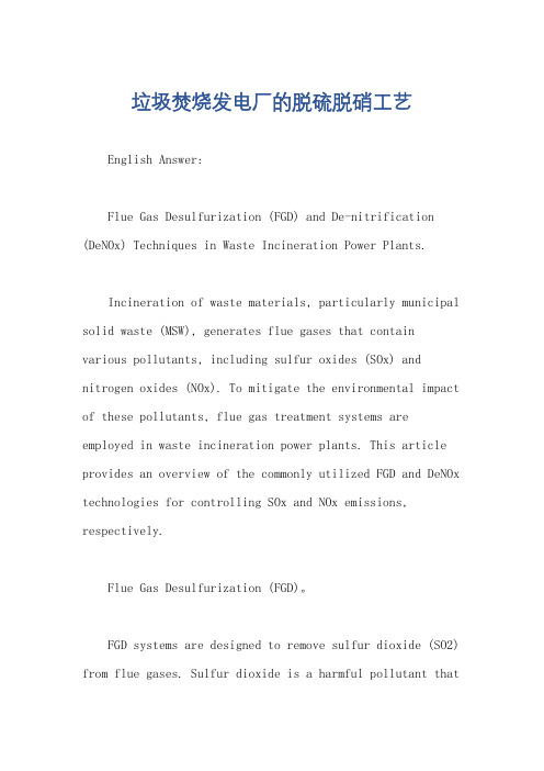
石灰石/石 膏法的烟气 脱硫系统图
1—锅炉;2—电除尘器;6—吸收塔;9—氧化用空气;10—工艺过程用水;11—粉状石 灰石,13—粉状石灰石贮仓;14—石灰石中和剂贮箱;15—水力旋流分离器;16—皮带 39 过滤机;17—中间贮箱;18—溢流贮箱;20—石膏贮仓;21—溢流废水,22—石膏
三、海水烟气脱硫
• 海水因具有—定的天然碱度和特定 的水化学特性被用于烟气脱硫 • 海水烟气脱硫工艺适用于燃煤含硫 量不高并以海水为循环冷却水的海
边电厂
40
海水烟气脱硫工艺的主要特点
1. 工艺简单,无需脱硫剂的制备,系统可靠, 可用率高 2. 系统脱硫效率高,—般可达90% 3. 不需添加脱硫剂,也无废水废料处理问题 4. 与其它湿法脱硫工艺相比,投资省,运行费 用低 不足之处: 1. 其应用有局限性,只能用于海边电厂,适用 于燃煤含硫量不大于1.5%的中低硫煤 2. 重金属和多环芳烃的浓度不能超过规定的排 放标准
34
石灰石/石膏法
• 石灰石/石膏法和石灰石/石灰法最主 要的区别就是,向吸收塔的浆液中鼓入 空气,以强制使100%的CaSO3均氧化成 CaSO4(石膏)。这样,脱硫以后的固体副 产品不再是废物而需抛弃,而是有用的 石膏产品
35
石灰石/石膏法的优点
1. 吸收塔将洗涤循环、石灰石溶解、强制空气氧化 及石膏结晶结合为—体; 2. 洗涤循环底槽内有机械搅拌和氧化空气分配系统; 3. 石灰石粉与水混合制浆后定量加入吸收塔内; 4. 引风机位于吸收塔烟气入口,没有腐蚀和结垢的 问题,吸收塔正压运行; 5. 采用回转式气/气烟气再热器,利用原烟气自身 热能加热洗涤脱硫后的冷湿烟; 6. 石膏浆液经水力旋流分离器和真空皮带过滤器脱 水及热烟气干燥处理,最终副产品为粉状或块状 石膏; 7. 在燃煤含硫量为 0.7%~2.5% 时, Ca/S = 1.0~1.5 , 可以达到 90%~99.2%的脱硫效率。对于含硫量高 于3%的煤种,其运行经验较少 36
垃圾焚烧发电厂生产流程
垃圾焚烧发电厂生产流程英文回答:Waste-to-Energy (WtE) Power Plant Process Flow.Waste-to-energy (WtE) power plants convert non-recyclable waste into electricity and heat. The process involves several key stages:1. Waste Acceptance and Sorting: Waste is delivered to the plant and subjected to preliminary sorting to remove recyclable materials and hazardous substances.2. Waste Preparation and Storage: Non-recyclable waste is shredded or pulverized to reduce its size and increase its surface area. The shredded waste is then stored in bunkers or silos until ready for combustion.3. Combustion: The shredded waste is fed into a combustion chamber and burned at high temperatures in acontrolled environment. The combustion process generates heat and releases flue gases.4. Heat Recovery: The heat generated by combustion is captured by a boiler to produce steam. The steam is then used to drive a turbine generator to produce electricity.5. Flue Gas Cleaning: The flue gases produced during combustion contain pollutants such as particulates, sulfur oxides (SOx), and nitrogen oxides (NOx). These gases are cleaned using various technologies, such as scrubbers, electrostatic precipitators, and selective catalytic reduction (SCR) systems.6. Ash Handling: The combustion process produces bottom ash and fly ash. Bottom ash is removed from the combustion chamber and quenched with water. Fly ash is collected from the flue gas cleaning system. Both types of ash are disposed of or recycled.7. Energy Distribution: The electricity generated by the WtE plant is distributed to the power grid and can beused to power homes, businesses, and other consumers. The heat generated can also be used for district heating or other industrial purposes.中文回答:垃圾焚烧发电厂生产流程。
水泥英语词汇
烧成窑尾 Cyclone Preheater
熟料储存及次熟料库 Clinker Storing and Under-Burned Clinker Silo
熟料输送 Clinker transportation
水泥粉磨及输送 Cement Grinding and Transportation
原料处理变电所 Raw Treatment Substation
水泥包装及纸袋库 Cement Packing and Bag House
熟料储存、石膏破碎及输送 Clinker Storing Gypsum Crushing and Transportation
废气处理 Waster Gas Treatment
水泥包装及袋装水泥发运 Cement Packing and Bagged Cement Dispatching
空压机站 Compressed Air Station
烧成窑中及三次风管 Kiln and Tertiary Air Duct
中央控制室 Central Control Room
熟料储存、石膏破碎及输送 Clinker Storing Gypsum Crushing and Transportation
废气处理 Waster Gas Treatment
水泥包装及袋装水泥发运 Cement Packing and Bagged Cement Dispatching
原料粉磨及废气处理 Raw Material Grinding and Exhaust Gas Treatmen
烧成窑头 Cooler
水泥储存及汽车水泥散装站 Cement Storing and Bulk Loading Station For Truck
催化裂化烟气钠法脱硫技术问题分析与对策_胡敏
钠法脱硫工艺因 NaOH 对 SO 2 亲和力强 , 具 有脱硫效率高 , 脱硫生成物在吸收塔 ( 洗 涤 塔 ) 和吸收剂 循 环 系 统 不 易 结 垢 和 堵 塞 , 系统故障 , , 少 投资较低等特点 已广泛应用于催化裂化烟 气脱硫 。
1
钠法脱硫工艺
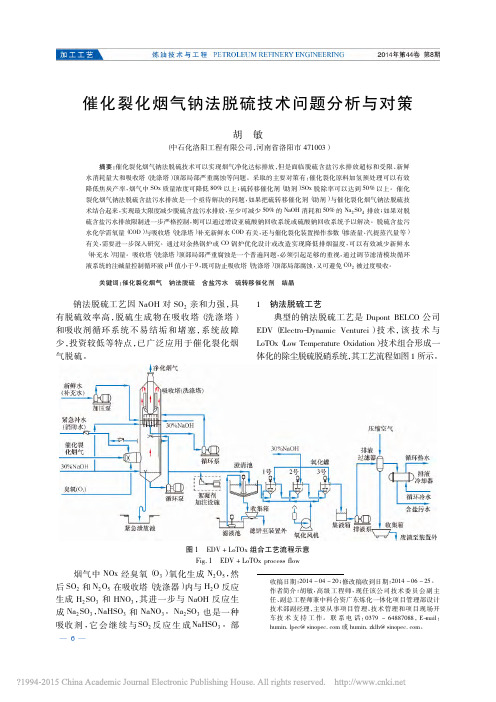
典型的钠法脱硫工艺是 Dupont BELCO 公司 EDV ( ElectroDynamic Venturei ) 技 术, 该技术与 LoTOx( Low Temperature Oxidation) 技术组合形成一 体化的除尘脱硫脱硝系统, 其工艺流程如图 1 所示。
— 6 —
使总悬浮固 分含盐污水经沉降分离和氧化预处理, 体量( TSS) 和化学需氧量( COD) 达标后排出装置。 烟气中 SO2 和 N2 O5 与 NaOH 的主要化学反应: 2NaOH + SO2 → Na2 SO3 + H2 O ( 运行初期, pH > 9 ) Na2 SO3 + H2 O + SO2 → 2NaHSO3 ( 正常运行, 5 < pH < 9 ) NaHSO3 + NaOH → Na2 SO3 + H2 O N2 O5 + H2 O → 2HNO3 HNO3 + NaOH → NaNO3 + H2 O 钠法脱硫过程实际上是利用循环吸收液系统 中的 Na2 SO3 吸收烟气中的 SO2 ,NaHSO3 浓度增 加会 导 致 吸 收 能 力 下 降, 需 补 充 NaOH 使 部 分 NaHSO3 转化为 Na2 SO3 , 以维持循环吸收液系统 中 Na2 SO3 浓度相对稳定, 才能保证吸收效果。 1] 据文献[ 报道, 随着吸收塔 ( 洗涤塔 ) 循环 pH 吸收液 pH 值增大, 烟气 SOx 脱除率逐渐变大, 值与 SOx 脱除率的关系如图 2 所示, 当 pH 值大 于 7 时, 脱除率大于 95% ; 当 pH 值为 6 ~ 7 时, 脱 除率仍可维持在 90% 以上; 当 pH 值小于 5 时, 脱 除率小于 20% 。当 pH 值约为 4. 5 时,Na2 SO3 全
垃圾焚烧发电厂的脱硫脱硝工艺
垃圾焚烧发电厂的脱硫脱硝工艺English Answer:Flue Gas Desulfurization (FGD) and De-nitrification (DeNOx) Techniques in Waste Incineration Power Plants.Incineration of waste materials, particularly municipal solid waste (MSW), generates flue gases that contain various pollutants, including sulfur oxides (SOx) and nitrogen oxides (NOx). To mitigate the environmental impact of these pollutants, flue gas treatment systems are employed in waste incineration power plants. This article provides an overview of the commonly utilized FGD and DeNOx technologies for controlling SOx and NOx emissions, respectively.Flue Gas Desulfurization (FGD)。
FGD systems are designed to remove sulfur dioxide (SO2) from flue gases. Sulfur dioxide is a harmful pollutant thatcan contribute to acid rain and respiratory problems. The most common FGD technologies include:Wet Scrubbing: This method utilizes a scrubbing liquid, typically limestone or lime slurry, to absorb SO2 from the flue gases. The scrubbing liquid is then treated to remove the captured sulfur.Dry Scrubbing: In this process, a dry sorbent, such as lime or sodium bicarbonate, is injected into the flue gases. The sorbent reacts with SO2 to form a solid product, whichis removed from the system.Spray Dry Absorption: This technique combines features of both wet and dry scrubbing. A scrubbing liquid issprayed into the flue gases, which then reacts with a dry sorbent to form a solid product that is removed.De-nitrification (DeNOx)。
兰炭烘干机英文介绍
Blue carbon is also called carbocoal ,coke powder, is made by using high quality Jurassic clean coal block teemed with ShenFu coalfield, as a kind of new type carbon materials, with its high fixed carbon, high specific resistance, high chemical activity, low ash content, low aluminum content, low sulfur content and low phosphorus characteristics, gradually replace metallurgical coke and widely used in calcium carbide, ferroalloy, ferrosilicon, Silicon carbide and other products production, become a kind of irreplaceable carbon materials.Blue carbon (people also say semicoke, coke), structure for massive, the grain size general above 3 mm, the pale black color, at present, blue carbon basically have two kinds of specifications: one is the soil refined blue carbon, the other is machine-made blue carbon. Although two specifications blue carbon uses the same quality coal refining into, but because of the different production technology and equipment, its cost and quality are different.Blue carbon dryer is mainly composed by the barrel, transmission device, riding wheel device, raising material plate, sealing equipment etc. Our company with many years of practical experience developed new high efficiency energy saving rotary dryer. Compared with the traditional rotary dryer, the drying efficiency is higher, energy consumption is lower, yield is higher, running is more stable, sealing is better, widely adaptive and deeply user’s praise and recognition.The main performance characteristics1, heat source select fluidized bed furnace:Fuel of this type wide adaptability, can use all sorts of coal, especially use almost no volatile coke or coke breeze. Combustion temperature is lower, inburning process can effectively control the emissions of Nox and Sox, is a "clean" combustion technology, burn-off rate is high, high thermal efficiency; great section thermal intensity, the bed layer’s heat transfer ability is high, can reduce the furnace hearth volume and steel consumption. Load regulation broad/covering a wide range, heating stability properties is good, Ignition convenient, damping-down time is long, lime-ash is not easy to soften or cementation, activity good, easy to comprehensive utilization.2, efficiently combination raising material plateAccording to the physical property changes in the drying process of the material, uses many kinds of structure of combination raising material plate, make the material in the cylinder to form even material curtain, and with the hot flue gas fully proceed heat transfer and mass transfer, as to the high humidity viscous material, will have the jam resistance materials and break to accumulate the ball chain device. As to good liquidity material, the spoon-type of arc plate, etc. So let the unit volume evaporation strength reach to 40 ~ 80 kg/m3. H, evaporation strength improve 50 ~ 100% than the traditional rotates dryer.3, “Adjust center” riding wheel deviceUsing bearing type and structure form which different from the traditional dryer’s riding wheel, riding wheel and tyre self-constrain and keep line contact, the friction surface contact more board and equilibrium, to ensure the service life of riding wheel and tyre, enhance the cylinder operation stability. And properly reduce included angle between riding wheels, reduce operation resistance, lower power consumption.4, reasonably adjust rotate speedAccording to differ physico-chemical properties of drying material, drying retention time are different, design adopts the best rotate speed operation, fullyguarantee the drying quality, general equip with electromagnetic speed regulation motor or frequency control motor speed motor.5, design of dust collecting tail coverAccording to the requirements of different dry material, enlarge cavity design tail cover and change the exhaust flow, let the tail cover to get primary role to collect dust, greatly reducing the collect dust pressure to subsequent dust collector.6, new type sealing deviceThe dryer’s before and after seal ring take example by rotary kiln seal device, composed by maze/ labyrinth device, heat resistance andwear-resisting, sealed performance is good, long service life, convenient installation and maintenance.technical parametersHZG2200X20 70Y225M-630 JZQ750 20000X3620X3570 36.07 HZG2400X24 63.3 3.85Y225M-630 JZQ850 14000X3860X3760 59.9HZG2800X24 147.8 Y225M-675 JZQ850 15000X4060X3960 97HZG320025 176.5 5Y225M-675 JZQ1000 25000x5000x4500 110。