外文翻译封面
2、英文翻译封面格式范例
(3)英文原著若为纸质复印件或不可更改的pdf格式文件,则英文原著与中文翻译单独编制页码;除上述情况外,英文原著与中文翻译整体编制页码。
(4)建议在英文原著首页以页脚的形式注明英文原著的来源,如本页下题注所示,书写格式同正文中的参考文献格式要求。
英文翻译
题目:
Development of LCD Telephone Alarm System
专业班级:
2010电子信息工程01
学号:
XБайду номын сангаасX
姓名:
XXX
指导教师:
XXX教授
XXX高工(校外)
学院名称:
电气信息学院
201年月日
说明:(1)翻译内容的正文格式同毕业设计(论文)格式,也应该有“武汉工程大学毕业设计(论文)说明书”字样的页眉;
3-外文翻译模板格式及要求
杭州电子科技大学毕业论文外文文献翻译要求根据《普通高等学校本科毕业设计(论文)指导》的内容,特对外文文献翻译提出以下要求:一、翻译的外文文献可以是一篇,也可以是两篇,但总字符要求不少于1.5万(或翻译成中文后至少在3000字以上)。
二、翻译的外文文献应主要选自学术期刊、学术会议的文章、有关著作及其他相关材料,文献作者最好为国外的专家或学者;应与毕业论文(设计)主题相关,并作为外文参考文献列入毕业论文(设计)的参考文献。
并在每篇中文译文首页用“脚注”形式注明原文作者及出处,中文译文后应附外文原文。
脚注的方法:插入----引用---脚注和尾注三、中文译文的基本撰写格式为:1.题目:采用小三号、黑体字、居中打印,段前段后1行间距;;2.正文:采用小四号、宋体字,行间距为固定值20磅,标准字符间距。
页边距为左3cm,右2.5cm,上下各2.5cm,页面统一采用A4纸。
英文原文如为word文档,请用罗马字体排版,段前空两格,段间距20磅。
页眉为“杭州电子科技大学本科毕业论文外文翻译”,5号宋体字从正文开始编写页码,页码居中。
四、封面格式由学校统一制作(注:封面上的“翻译题目”指中文译文的题目),填充内容为加粗小三号楷体_GB2312,并按“封面、译文一、外文原文一、译文二、外文原文二、考核表”的顺序统一装订。
五、忌自行更改表格样式,学号请写完整。
封面和考核表均为一页纸张,勿换行换页。
注意:1.除了封面和考核表之外,外文翻译有页眉和页码。
2.外文翻译中各级标题统一为段前空两格;若标题无序号,也可按与原文一致的原则处理。
题目段前段后1行一级标题小四宋体加黑,段前段后0.5行其他各级标题段前空两格,小四宋体不加黑,其他与正文要求一致。
毕业论文外文文献翻译毕业设计(论文)题目Xxx(单击此处添加论文题目)翻译(1)题目指翻译后的第一篇中文译文的题目翻译(2)题目指翻译后的第二篇中文译文的题目若无,则本栏留空学院经贸学院专业国际经济与贸易(单击此处添加专业)姓名XXXXXX(单击此处添加姓名)班级XX020811(单击此处添加班级)学号XX023101(单击此处添加班级)指导教师XXXXXX(单击此处添加指导教师)单击此处添加翻译后的第一篇中文译文的题目1 [单击此处添加译文正文]一、单击此处添加一级标题1[单击此处添加译文正文]1.[单击此处添加译文正文]2.[单击此处添加译文正文]3.[单击此处添加译文正文]二、单击此处添加一级标题2[单击此处添加译文正文]1.[单击此处添加译文正文]2.[单击此处添加译文正文]3.[单击此处添加译文正文]三、单击此处添加一级标题3……………………………以下是模板的使用方法说明文字,正式成文后请删除。
外文翻译格式说明
山东理工大学毕业设计(外文翻译材料)学院:专业:学生姓名:指导教师:电气与电子工程学院自动化于小涵季画外文翻译材料格式要求:1.页边距:上3.8磅;下3.8磅;左3.2,右3.2;页眉距边界2.8,页脚距边界32.原文题目:Arial,小三;间距:段前18磅,段后12磅,间距21磅3.原文正文:Times New Roman,小四;间距:段前0磅,段后6磅,间距21磅4.译文题目:黑体,小三;间距:同原文题目5.译文正文:宋体,小四;间距同原文正文6.页眉页脚:原文页眉处写:外文翻译(原文),宋体,五号。
译文页眉处写:外文翻译(译文),宋体,五号。
原文译文的页脚统一编页码(不要单独编页码)。
Plant Model Generation for PLC SimulationHyeong-Tae ParkAbstract:This paper reports an automated procedure for constructing a plant model for PLC simulation. Since PLC programs contain only the control logic without information on the plant model, it is necessary to build the corresponding plant model to perform the simulation. Conventionally, a plant model for PLC simulation has been constructed manually, which requires much effort and indepth knowledge of the simulation. As a remedy for this problem, we propose an automated procedure for generating a plant model from the symbol table of a PLC program. To do so, we propose a naming rule for PLC symbols so that the symbol names include sufficient information on the plant model. By analysing such symbol names, we extract a plant model automatically. The proposed methodology has been implemented and test runs performed.Keywords: agile manufacturing; CAD/CAM; CAPP; simulation1. IntroductionTo survive and prosper in the modern manufacturing era, manufacturers need to continuously improve their products, as well as their production systems. A modern manufacturing line is a highly integrated system composed of automated workstations, such as robots with tool-changing capabilities, a hardware handling system and storage system, and a computer control system that controls the operations of the- 1 -entire system.Since the implementation of a manufacturing line requires heavy investment, proper verification of a line’s operational status sho uld be performed to ensure that the highly automated manufacturing system will successfully achieve the intended benefits. Simulation technology is considered to be an essential tool in the design and analysis of complex systems that cannot be easily described by analytical or mathematical models . Simulation is useful for calculating utilisation statistics, finding bottlenecks, pointing out scheduling errors, and even for creating manufacturing schedules. Traditionally, various simulation languages, including ARENA and AutoMod, have been used for the simulation of manufacturing systems. These simulation languages have been widely accepted both by industry and by academia; however, they remain as analysis tools for the rough design stage of a production line, because their simulation models are not sufficiently realistic to be utilised for a detailed design or for implementation purposes. For example, real production lines are usually controlled by PLC (Programmable Logic Controller) programs (Rullan 1997), but conventional simulation languages roughly describe the control logic with independent entity flows (job flows) between processes.- 2 -Production systems typically consist of simultaneously operating machines, which are controlled by PLCs, currently the most suitable and widely employed industrial control technology. A PLC emulates the behaviour of an electric ladder diagram. As they are sequential machines, to emulate the workings of parallel circuits that respond instantaneously, PLCs use an input/output symbol table and a scanning cycle. When a program is being run in a PLC it is continuously executing a scanning cycle. The program scan solves the Boolean logic related to the information in the input table with that in the output and internal relay tables. In addition, the information in the output and internal relay tables is updated during the program scan. In a PLC, this Boolean logic is typically represented using a graphical language known as a ladder diagram (IEC 2003).Since the abstraction levels of conventional simulators and PLC programs are quite different, the control logic of conventional simulators cannot be reused for the generation of PLC programs. Usually, electrical engineers manually write PLC programs by referring to the rough control logic of conventional simulators, as shown in Figure 1. Since PLC programming is a very tedious and error-prone job, it is essential to verify the PLC programs offline to reduce the stabilisation time of a production system.Previous approaches to a PLC program can be categorised into two groups:- 3 -(1) verification of a given PLC programand (2) generation of a dependable PLC program. In the first group, various software tools have been developed for the verification of PLC based systems via the use of timed automata, such as UPPAAL2k, KRONOS, Supremica and HyTech, mainly for programs written in a statement list language, also termed Boolean (Manesis and Akantziotis 2005). Such software tools verify PLC programs to a certain extent; however, they remain limited. Since they mainly focus on the checking of theoretical attributes (safety, liveness, and reachability), it is not easy for users to determine whether the PLC programs actually achieve the intended control objectives. In the second group, many researchers have focused on the automatic generation of PLC programs from various formalisms including state diagrams, Petri nets, and IDEF0. These formalisms can help the design process of control logics; however, it is still difficult to find hidden errors, which is the most difficult part of verifying a control program.Figure 2. The concept of PLC simulation.To overcome the aforementioned problems, it is necessary to utilise simulation techniques for PLC program verification. By simulating PLC programs, it is possible to analyse the control logic in various ways and recognise hidden errors more intuitively (David 1998). Although PLC simulation can be a very powerful tool for the detailed verification of a production system, the accompanying construction of a plant model is a major obstacle (the counterpart model of a control program). Since PLC programs only contain the control information, without device models, it is necessary to build a corresponding plant model to perform simulation, as shown in- 4 -Figure 2. However, constructing a plant model requires an excessive amount of time and effort. Sometimes, the plant model construction requires much more time than the PLC programming. This serves as the motivation for exploring the possibility of finding an automatic procedure for generating a plant model from a given PLC program.Figure3.Symbol table of a PLC program.Although the objective of a PLC program is not to describe a plant model (device models), the symbol table of a PLC program can provide a glimpse of the plant model. As shown in Figure 3, symbols in a PLC program usually contain some information related to the plant. For example, ‘EXLINE_MB_AGV_P1’ means that the symbol is a signal that is related to the control of an ‘AGV’ (Auto Guided Vehicl e) belonging to the ‘MB’ station of ‘EXLINE’ line. The above scenario reveals the key idea of the present study. If we can develop a proper naming rule for PLC symbols, then it might be possible to extract a plant model by analysing the symbol names.This paper has two major objectives: (1) to propose a proper naming rule for PLC symbols and (2) to develop a procedure for generating a plant model by analysing the symbol names. The application area of the proposed methodology includes all types of automated manufacturing systems controlled by PLC programs, such as automotive production lines, FMSs (flexible manufacturing systems), and ASRSs (automatic storage and retrieval systems). The overall structure of the paper is as follows. Section 2 addresses the specifications of a plant model for PLC simulation. Section 3 describes a naming rule for PLC symbols, which enables the automatic generation of a plant model. Finally, concluding remarks are given in Section 4.2. Plant model for PLC simulationBefore explaining the specification of a plant model enabling PLC simulation, we want to address the importance of the PLC simulation. Chuang et al. (1999) proposed a procedure for the development of an industrial automated production system that- 5 -- 6 -consists of nine steps, as follows: (1) define the process to be controlled; (2) make a sketch of the process operation; (3) create a written sequence of the process; (4) on the sketch, add the sensors needed to carry out the control sequence; (5) add the manual controls needed for the process setup or for operational checks; (6) consider the safety of the operating personnel and make additions and adjustments as needed;(7) add the master stop switches required for a safe shutdown; (8) create a ladder logic diagram that will be used as a basis for thePLC program; and (9) consider the possible points where the process sequence may go astray. The most time-consuming task for the control logic designers is the eighth step, which is usually done by the repetitive method of code writing, testing, and debugging until the control objectives are achieved (Manesis and Akantziotis 2005). This is the reason why conventional PLC programming is often inefficient and prone to human error. As the configurations of production lines and their control programs become more complicated, there is a strong need for a more efficient PLC simulation environment. It is hoped that this paper will take positive steps in this direction.A PLC can be considered as a dedicated computer system having input and output signals. To run a PLC, the corresponding plant model (the counterpart system) is required to interact with the input and output of the PLC. The behaviour of the plant model should be the same as that of the actual system to achieve PLC verification. Since a production line consists of various devices, including robots, transporters, jigs, solenoids, proximity sensors, and light sensors (Groover 2006), we can consider a plant model as a set of device models. To build such a device model, this paper em ploys Zeigler’s DEVS (Discrete Event Systems Specifications) formalism (Zeigler 1984, Kim 1994), which supports the specification of discrete event models in a hierarchical, modular manner. The semantics of the formalism are highly compatible with object-oriented specifications for simulation models. We use the atomic model of the DEVS formalism to represent the behavior of a device model. Formally, an atomic model M is specified by a 7-tuple:M =〈X, S,Y, sin δ,ext δ,λ ,t a 〉X input events setS sequential states setY output events setsin δ S→S: internal transition functionext δQ*X→S: external transition functionQ={(s, e)∣s ∈S, 0≤e ≤t a (s)}: total state of MλS →Y: output function- 7 -t a S →Real: time advance functionThe four elements in the 7-tuple, namely sin δ,ext δ,λand t a , are called the characteristic functions of an atomic model. The atomic model of the DEVS formalism can be considered as a timed-FSA (finite state automata), and it is suitable for describing the behaviour of a device model. Once the device models (plant model) are obtained, it becomes possible to perform the PLC simulation. Currently, device models should be construed manually, which takes much time and effort. To cope with the problem, the objective of the paper is to propose an automated generation procedure for device models.Before explaining the automatic generation procedure of a plant model, let us take a look at the manual procedure to construct device models. To construct a device model, first it is necessary to identify the set of tasks that are assigned to the device. The activation of each task is normally triggered by an external signal from PLC programs. Once the set of tasks is identified for a device, it is then possible to extract the state transition diagram, which defines an atomic model of the DEVS formalism. Figure 4(a) shows a simple example of an AGV (Automatic Guided Vehicle) with two tasks, T1 (movement from p1 to p2) and T2 (movement from p2 to p1). As the two tasks should be triggered by external events, the shell part of the AGV must have two input ports, termed here as Signal_1 and Signal_2, as shown in Figure 4(b).From the set of tasks, it is possible to instantiate the state transition diagram. For this example, there are four states, P1, DoT1, P2 and DoT2. While P1 and P2 take external events from the input ports (Signal_1, Signal_2) for state transitions, DoT1 and DoT2 take internal events that are the end events of the two tasks (T1 and T2). The DEVS atomic model of the virtual device, corresponding to the AGV, can be described as follows:- 8 -Shell of a virtual device:M=〈X,S,Y,sin δ,ext δ,λ ,t a 〉}2_,1_{Signal Signal =X S={P1,DOT1,P2,DOT2} Y={T1Done,T2Done}sin δ(DOT1)=P2 s i nδ(DOT2)=P1 ext δ(P1,Signal_1)=DOT1 ext δ(P2,Signal_2)=DOT2λ(DOT1)=T1Done λ(DOT2)=T2Donet a (DOT1)=Time_1 t a (DOT2)=Time_2Once a plant model has been constructed, it is possible to perform the PLC simulation, which enables the intuitive verification of a PLC program. Figure 5 shows the connections between a PLC program and a plant model. The plant model includes all device models of a production system, and the PLC program contains the control logic for the plant model. To integrate the plant model and the PLC program, it is necessary to define the mapping between the plant model and the PLC program, which is described by I/O mapping. To enable the visual verification of a PLC program, it is necessary to import 3D graphic models, which are controlled by the logical device models (the state transition diagrams). Since 3D graphic models are not always necessary, they are optional for PLC simulation. As mentioned already, the objective of this paper is to extract device models from the symbol names of PLC programs. To do so, it is necessary to develop a proper naming rule for PLC symbols. The naming rule will be addressed in the next section.3. Symbol naming for plant model generationAlthough IEC 61131-3 provides various standard specifications for a PLC, the naming rules of PLC symbols have rarely been brought into focus. Since there have been no standard rules for the naming of PLC symbols, it has been fully dependent on individual PLC programmers.To generate device models from PLC symbols, it is necessary to make PLC symbols that include enough information concerning the plant model. To achieve this objective, we interviewed many PLC programmers and analysed various conventional rules. As a result, we came up with a naming structure consisting of five fields: (1) line name, (2) process number, (3) device name, (4) input or output, and (5) task name (or state name). Figure 6 shows the naming structure for PLC symbols.If the PLC symbols are named according to the proposed naming structure, then it becomes possible to extract device models (atomic models of DEVS formalism) by simply analysing the symbol names. There are two types of symbols (signals), input or output, which are specified by the fourth field. The purpose of the output signal is to trigger a task that is specified by the fifth field. Thus, it is possible to identify the set of tasks of a device by analysing the output symbols. As mentioned already, once the set of tasks is identified for a device, it is then possible to extract the state transition diagram for the device model, which defines an atomic model of the DEVS formalism. While an output signal (symbol) is issued by a PLC to trigger a task, an input signal (symbol) is issued by a device to report the completion of the task to theδand internal transition functions PLC. This means that external transition functionsextδof a device model can be automatically extracted from the output and input sinsymbols, respectively. We demonstrate the generation procedure of a plant modelfrom PLC symbols using an example, as shown in Figure 7.- 9 -- 10 -In the example cell, we assume a part is loaded manually on the AGV by a worker. When the AGV senses the existence of a part, it moves to transfer the part to the machine. After the transfer, the machine performs machining to convert the part into a finished product. In this case, the plant model consists of two device models: an AGV model and a machine model. The PLC program to control the simple manufacturing cell is shown in Figure 8(a), and its symbol table is shown in Figure 8(b).As shown in Figure 8(b), the AGV model has two output symbols and two input symbols. From the output symbols (EX_OP_AGV_O_GOP1, EX_OP_AGV_O_GOP2), we can intuitively recognise that the AGV has two tasks- 11 -(movement from P2 to P1, and movement from P1 to P2). By using the output symbols, we can extract the state transition diagram, as well as the external transitionfunctions, as shown in Figure 9(a).As mentioned already, an output symbol triggers a task of a device model, and an input symbol is made by the device to notify the completion of the task. Since the execution of a task is performed internally by the device, the internal transition functions of a device model can easily be extracted from the input symbols(EX_OP_AGV_I_DONEGOP1, EX_OP_AGV_I_DONEGOP2). In this way, the device model of the machine can be extracted from the related symbols(EX_OP_MC_, etc.), as shown in Figure 9(b). The procedure for the construction of a device model can be described as follows.- 12 -(1) Identify all corresponding pairs between output symbols and input symbols. While an output symbol triggers a task, the corresponding input symbol reports the completion of the task. For example, EX_OP_AGV_O_GOP1 corresponds toEX_OP_AGV_I_DONEGOP1. (2) Define the states of a device mode using the last naming fields of input/output symbols. In the case of the AGV, we can define four states, GoP1, DoneGoP1, GoP2, and DoneGoP2. (3) Define external (internal) transition functions using output (input) symbols. Once a plant model has been obtained, it becomes possible to perform the PLC simulation by defining the I/O mapping relations between the plant model and the PLC symbols. Through the PLC simulation, we can efficiently check whether the PLC program achieves the control objectives or not.The proposed methodology was implemented in C++language, and test runs were made on a personal computer, as shown in Figure 10. The PLC program shown in Figure 8(a) was written using GX IEC developer version 7.0 provided byMitsubishi Electric Corporation. The GX IEC developer can export a symbol table in the form of an Excel file, as shown in Figure 8(b). The exported symbol table becomes the input for the generation of a plant model. Figure 10 shows that the generated device models by analysing the exported symbol table.4. Discussion and conclusionsThrough PLC simulation, it is possible to analyse control logic in various ways and recognise hidden errors more intuitively. Although PLC simulation can be a very powerful tool for the detailed verification of a production system, the accompanying construction of a plant model requires too much time and effort. To remedy this problem, we have proposed an automated procedure to generate a plant model from the symbol table of a PLC program. To do so, we have also proposed a naming rule for PLC symbols so that the symbol names include sufficient information on the plant model. By analysing the symbol names, a plant model can be extracted automatically. Since a plant consists of various manufacturing devices, we can consider a plant model as a set of device models. To represent such a device model, the proposed method employs Zeigler’s DEVS formalism. We use the atomic model of the DEVS formalism to describe the logical behavior of a device model. In other words, it is necessary to extract the device models from the symbol table in the form of an atomic model of the DEVS formalism. Although the proposed methodology only deals with the local verification of PLC programs, it is also possible to extend the methodologyto include the verification of mechanical aspects of the plant .- 13 -工厂模型生成PLC仿真Hyeong-Tae Park摘要 :本文介绍一个自动程序可编程序控制器(PLC)生成工厂模型仿真。
毕业设计(论文)英文献翻译封面
third-party logistics problems, causes and strategic choiceAbstract: China's logistics industry has just started, third-party logistics and other aspects of the theory and practice are relatively weak. The paper points out the problems of the Third Party Logistics is the gap between domestic and international third party logistics, logistics efficiency is not high, the lack of systematic management, and logistics platform to build lag behind the concept of logistics management, and so on. Analyzed the causes of such problems arising and proposed lean logistics, small and medium enterprise value chain alliances third party logistics, large third-party logistics companies such as virtualization strategy choice of three third-party logistics enterprise development strategies.Keywords:Third party logistics;lean logistics strategy;value chain alliances; virtualization strategy1. IntroductionFor a long time, China's domestic enterprises procurement, transportation, warehousing, agents, packaging, processing, distribution and other aspects of control is not strong, in the "Procurement black hole", "Logistics trap" in the waste is difficult to calculate losses. Therefore, third-party logistics research, the overall effectiveness in promoting the improvement of China's economy has a very important theoretical and practical significance. This article attempts to my policy of three logistics problems and analysis of the causes of and propose several possible third-party logistics strategic choice.2 Third party logistics industry in China's major problems(A) The national policy of three logistics companies and foreign big gap between third-party logistics companies, specifically in the following areas:1, economies of scale and capital gap significantly. Because third-party logistics companies large foreign strategic departure from the global business, its advantages ofscale and capital is no doubt, especially start-up period of three logistics policy I, its very small size, strong capital that foreign giants China enterprises to shame.2,I state policy of the logistics enterprises provide three logistics service level and quality control rather than foreign counterparts. When some domestic enterprise is still in logistics interpreted as "trucks, add warehouse logistics enterprises abroad already completed a series of standardized transformation. Meanwhile, foreign logistics organizational ability so powerful, Germany, for example, a third-party logistics company, all aspects of logistics experts across all over Europe. If the goods by a customer needs of different countries, so these experts from all over Europe in online design a the best logistics solutions. This provides solutions is the ability that the core competence of third-party logistics companies, unlike domestic companies claim to having many ship, how many car.3, China's accession to WTO, lower the threshold of the logistics industry. The logistics service industry: our commitment to all of the services sector, after a reasonable transition period, to cancel most of the foreign equity limit does not restrict access to foreign service providers the current market, do not restrict all the service sectors and the existing market access activities. The secondary distribution services while also making a similar commitment. These restrictions will be phased out after 3-4 years, during which foreign service providers can create a hundred per cent wholly-owned subsidiaries or business sector, the domestic logistics industry will face international competition.(B) serious waste of resources, third party logistics efficiency is not high. From the microscopic point of view, due to the impact of the planned economy, a long time many enterprises, especially state-owned enterprises to go the "large", "small" route, they have their own warehouse, fleet, and even ocean-going vessels team, resulting in wasting a lot of the logistics process, the specific performance of the idle warehouse, logistics decentralized operation, the low level of organization, transverse joint weak. And to provide integrated, modern, professional, punctual, efficient services to third-party logistics enterprises are very small. From a macro point of view of economic development of third-party logistics failed to keep up with the pace of the formation of industrial management model, but only with the transportation, telecommunications, commercial materials, foreign trade and other sectors of the integration and collaboration.(C) the lack of systematic management, equipment standardization is low. Most of the current third-party logistics enterprises in China under the traditional system based on materials circulation enterprises developed, the service mainly stay in the storage, transportation, lack of systematic management, logistics, low efficiency, lack of effective third party logistics functions Play. In addition, the fragmentation of China's logistics sector, making the link in the transportation logistics and equipment standards are not uniform, does not support current standards for physical facilities, resulting in the increase in third-party logistics invalid operation, speed, and reduce costs.(D) third-party logistics platform to build lag, lower degree of information technology. Third-party logistics and distribution platforms, including physical network and information network, physical network refers to the logistics facilities, transportation, transportation hubs in the geographical location of the rational distribution and the formation of physical network; information networks that use third-party logistics business and information technology, Information resources to their chain integration and the formation of a shared network of information resources. The status of physical network are: low levels of third-party logistics and equipment, and information networks also lack the necessary public logistics platform.(E) the concept of logistics management of domestic enterprises is still very backward, which greatly restricts the development of third party logistics. For example: Some companies believe that inventory information is confidential business information must be managed by the enterprises themselves, the class of business activities while outsourcing the management concept difficult to accept, often resulting in control of their own poor management of logistics, business competition in the market weakens Force.3Causes problems analysis(A) lack of modern logistics management knowledge and expertise of logistics personnel. This is the third-party logistics industry in restricting the development of China's most important one of the bottlenecks. Logistics knowledge, especially in modern integrated third party logistics knowledge is far from being universal, but that its main business areas is to provide transportation and warehousing services, not know that it isnew to these traditional business integration of its business fields Far too simple to become connected with transport and storage of raw materials, semi-finished products supply, production process, material flow, the whole process of product distribution services, as cover flow, solid logistics, capital flow, information flow is equal to the integrated system of systems.(B) fails to effectively use modern technology. This situation has greatly restricted the cultivation of third-party logistics companies, affecting their overall competitive strength increased. China's accession to the WTO, domestic enterprises will face third-party logistics strong competition from abroad, the domestic third-party logistics industry is difficult to provide low-cost, high quality and efficient service.(C) subject to the constraints of traditional management systems. Fragmentation in the traditional institutional arrangements, third party logistics activities have been separated from many different sectors such as transportation, post and telecommunications, foreign trade, domestic trade and only involves the transport industry to the Ministry of Railways, Ministry of Communications, etc. Some departments, the lack of efficient collaboration between departments, resulting in the transport process of rotation of the mode of transport and time-consuming part of the cost of logistics in the process of becoming "trap. " There are also procedures for customs management, material procurement and other aspects of some of the provisions of the logistics enterprises also raise the level of integrated services and business development areas, thus restricting the rapid development of third-party logistics industry.4 The third party logistics enterprise strategic choice Summarized the latest of several foreign logistics theory and the development of third-party logistics with the current practice of foreign, third-party logistics firm's strategic choice to have the following three:(A)Lean Logistics StrategySince the lag theory and practice of logistics, our most extensive third-party logistics company or business, it can not accurately position their logistics services. If you do not reverse this situation as soon as possible, will be third-party logistics industry in Chinahave restricted role. Lean production theory of logistics for our third-party logistics company provides a new development ideas for these enterprises to survive in the new economy and development opportunities. Lean Logistics concept originated in lean manufacturing. It is produced from the Toyota Motor Corporation 70 years in the last century by the original "Toyota Production System", after research by the Massachusetts Institute of Technology professor and summary, was published in 1990 published "change the world of machines), a book. Lean thinking is the use of various modern management methods and means, based on the needs of society to fully play the role of people as a fundamental and effective allocation and rational use of corporate resources to maximize economic benefits for enterprises to seek a new Management philosophy. Lean Logistics Lean Thinking is the application in logistics management, logistics development must reflect. The so-called Lean Logistics means: the process by eliminating the production and supply of non-value added waste in order to reduce stocking time, improve customer satisfaction. The aim of Lean Logistics according to customer needs, providing customers with logistics services, while pursuing the provision of logistics services in the process to minimize waste and delay, the process of increasing value added logistics services. Lean logistics system is characterized by its high-quality, low cost, continuous improvement, driven by customer demand oriented logistics system. It requires establishing the customer first thought, on time, accurate and fast delivery of goods and information.In short, Lean Logistics, as a new management ideas, bound to have a third-party logistics enterprises in China have far-reaching impact, it will change the appearance of the extensive third party logistics management concept, the formation of third party logistics Core competitiveness.(B)the establishment of small and medium third party logistics value chain alliance Third-party logistics enterprises of small and medium can not be independent because of their one-stop logistics services to provide full shortcomings, and because the small size of assets, services, not wide area so that small and medium enterprises in China's logistics third party logistics industry at a disadvantage. Therefore, third party logistics for small and medium enterprises, starting from their own resources to construct their own core competence is the key. As small and medium enterprise features of a single third-partylogistics and incomplete, so based on their respective core competencies based on the structure of the logistics business enterprise cooperation is an effective capacity to make up for deficiencies, constitutes a feasible way of competitive advantage of logistics. Value chain is the use of systems approach to investigate the interaction between business and the analysis of all activities and their access to the resources of competitive advantage. Value of the business activities fall into two categories: basic activities and support activities. Basic activities are involved in product creation and sale of the material transferred to the buyer and after-sales service activities. Basic activities of supporting activities is to assist the revenue by providing outsourcing, technology, human resources and a variety of functions to support each other. Theory to analyze the value chain study the value of third party logistics chain composition, can be found in auxiliary activities, third party logistics enterprise and general business is no different, the basic activities in the third-party logistics companies has its own characteristics. Third-party logistics enterprises there is generally no commodity production process, only the re-circulation process, does not account for major components of a wide range of third-party logistics companies and thus become the basic operating activities of storage, transport, packaging, distribution, customer service and marketing, etc. link. Various aspects of the basic work activities, due to their own limited resources and capacity, can not have every aspect of an advantage in that value chain in terms of some of the deficiencies, resulting in their overall logistics function not complete, lack of corresponding competitiveness and comparative advantage in some sectors of the value chain due to lack of overall effect should not play. Therefore, third party logistics industry, small and medium sized logistics enterprises within the Union, should be based on the value chain between complementary on the basis of cooperation, make full use of professional logistics companies and logistics functions of specialized logistics organization and coordination of agents Flexible complementary integrated logistics capabilities. Third-party logistics for small and medium enterprises, value chain should start with the advantage of links to explore and develop the core competitiveness of enterprises, through the reconstruction of the value chain to avoid weaknesses.(C)Large third-party logistics enterprise virtualization of strategyRapid development in IT and the Internet era, companies can not fight alone singles, but must be in the competition and collaboration, in cooperation and development. Thus, under modern conditions resulting from modern large-scale virtualized development of third-party logistics has a strong necessity. Large third-party logistics enterprise virtualization is the logistics management resources of others who will have "all", through the network, the other part into its own logistics, with the help of others break the power of physical boundaries, extending to achieve their various Function, and thus expand their ability to enhance their strength. Therefore, the logistics information technology, virtualization is a means for the connection and coordination of temporary and dynamic alliance in the form of virtual logistics. Integrated logistics virtualization technology as a means of electronic communication, customer-focused, based on the opportunity to participate in members of the core competencies as a condition to an agreement for the common pursuit of goals and tasks, the different parts of the country's existing Resources to quickly mix into a no walls, beyond the space constraints, by means of electronic networks, contact the unified command of the virtual business entity, the fastest launch of high-quality, low-cost logistics service.Modern large-scale virtualization, including third-party logistics functions, organization, geographic three virtualization. Virtualization capabilities with third-party logistics enterprise IT technology will be distributed in different locations, different companies take different functions within the logistics resources (information, human, material and other resources) organized to accomplish a specific task, to achieve the optimization of social resources. Virtualization refers to the organizational structure of the logistics organization is always dynamically adjusted, not fixed, but also decentralized, flexible, self-management, flat network structure, its objectives and in accordance with changes in the environment re-combination, in a timely manner Reflect the market dynamics. Virtual is the regional third party logistics network through the Internet link the global logistics resources, removing barriers and national barriers, to production management to achieve "virtual neighbors. "中国第三方物流存在的问题、原因及战略选择熊卫【摘要】中国物流业的发展才刚刚起步,第三方物流相关理论和实践等方面都相当薄弱。
外文翻译及外文原文(参考格式)
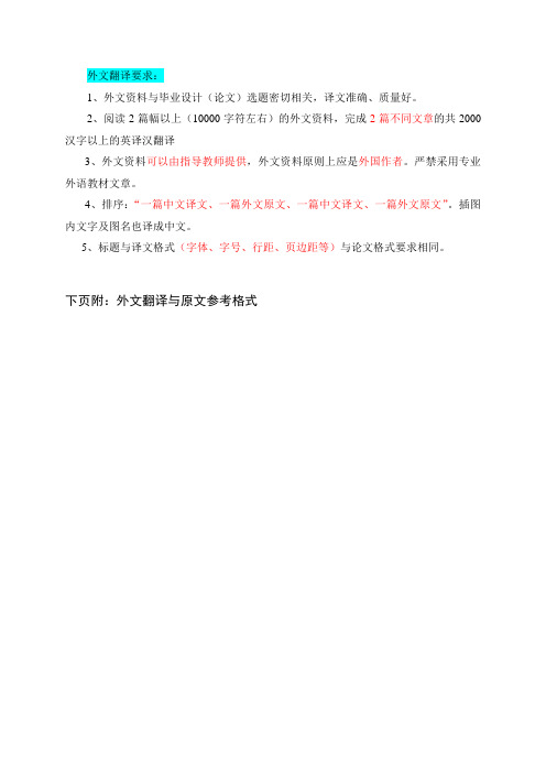
外文翻译要求:1、外文资料与毕业设计(论文)选题密切相关,译文准确、质量好。
2、阅读2篇幅以上(10000字符左右)的外文资料,完成2篇不同文章的共2000汉字以上的英译汉翻译3、外文资料可以由指导教师提供,外文资料原则上应是外国作者。
严禁采用专业外语教材文章。
4、排序:“一篇中文译文、一篇外文原文、一篇中文译文、一篇外文原文”。
插图内文字及图名也译成中文。
5、标题与译文格式(字体、字号、行距、页边距等)与论文格式要求相同。
下页附:外文翻译与原文参考格式2英文翻译 (黑体、四号、顶格)外文原文出处:(译文前列出外文原文出处、作者、国籍,译文后附上外文原文)《ASHRAE Handbook —Refrigeration 》.CHAPTER3 .SYSTEM Practices for ammonia 3.1 System Selection 3.2 Equipment3.10 Reciprocating Compressors第3章 氨制冷系统的实施3.1 系统选择在选择一个氨制冷系统设计时,须要考虑一些设计决策要素,包括是否采用(1)单级压缩(2)带经济器的压缩(3)多级压缩(4)直接蒸发(5)满液式(6)液体再循环(7)载冷剂。
单级压缩系统基本的单级压缩系统由蒸发器、压缩机、冷凝器、储液器(假如用的话)和制冷剂控制装置(膨胀阀、浮球阀等)。
1997 ASHRAE 手册——“原理篇”中的第一章讨论了压缩制冷循环。
图1.壳管式经济器的布置外文翻译的标题与译文中的字体、字号、行距、页边距等与论文格式相同。
英文原文(黑体、四号、顶格)英文翻译2(黑体,四号,顶格)外文原文出处:(黑体,四号,顶格)P. Fanning. Nonlinear Models of Reinforced and Post-tensioned Concrete Beams. Lecturer, Department of Civil Engineering, University College Dublin. Received 16 Jul 2001.非线形模型钢筋和后张法预应力混凝土梁摘要:商业有限元软件一般包括混凝土在荷载做用下非线性反应的专用数值模型。
外文翻译模板

本科生毕业论文(设计)外文参考文献译文本译文题目出处:作者单位作者姓名专业班级作者学号指导教师(职称)年月译文要求一、译文内容须与课题(或专业内容)联系,并需在封面注明详细出处。
二、出处格式为图书:作者.书名.版本(第×版).译者.出版地:出版者,出版年.起页~止页期刊:作者.文章名称.期刊名称,年号,卷号(期号):起页~止页三、译文不少于2000汉字。
四、翻译内容用小四号宋体字编辑,采用A4号纸双面打印,封面与封底采用浅蓝色封面纸(卡纸)打印。
要求内容明确,语句通顺。
五、译文及其相应参考文献一起装订,顺序依次为封面、译文、文献。
六、翻译应在第七学期完成。
译文评阅导师评语应根据学校“译文要求”,对学生译文翻译的准确性、翻译数量以及译文的文字表述情况等做具体的评价后,再评分。
评分:___________________(百分制)指导教师(签名):___________________年月日题 目(黑体3号, 字母、阿拉伯数字为Time New Roman5号加粗,居中,段前3行,段后2行)1.前言(黑体小3号, 字母、阿拉伯数字为Time New Roman 小3号加粗)×××××××××××××××××××××××××××××××××××××××××××××××××××××××××××××× (宋体小4号,行间距固定1.5倍行距,字符间距为标准)2. ×××××××××××××××××××××××××××××××,其×××××可表示如下:)2sin(101111path t f A E ϕϕπ++= (2-1) )2sin(202222path t f A E ϕϕπ++= (2-2)×××××××××××××××××××××××××××× (如表2-1所示)表2-1□××××××××××××××× ××× ××× ××× ××××× ×× ×× ×× ××××× ×× ×× ×× ××××× ×× ×× ×× ×××××××××××(表标题:位于表格上方,宋体5号,字母、阿拉伯数字为Time New Roman 5号,表内容:宋体5号,字母、阿拉伯数字为Time New Roman 5号)××××××××××××××××××××××××××× (如图2-1所示)图2-1□××××××××××(图标题:位于图下方,宋体5号,字母、阿拉伯数字为Time New Roman 5号)............................陕西师范大学本科生毕业论文(设计)外文参考文献译文本参考文献原文(纸质版可打印附后,电子版可截图附后)。
3-外文翻译模板
说明: 模板中的蓝色字体及红色字体为提示说明用,填写过程应删除。
3外文翻译模板外文翻译格式毕业论文外文翻译格式外文翻译外文翻译网站外文翻译范文外文文献翻译外文翻译怎么写谷歌翻译身份证翻译模板
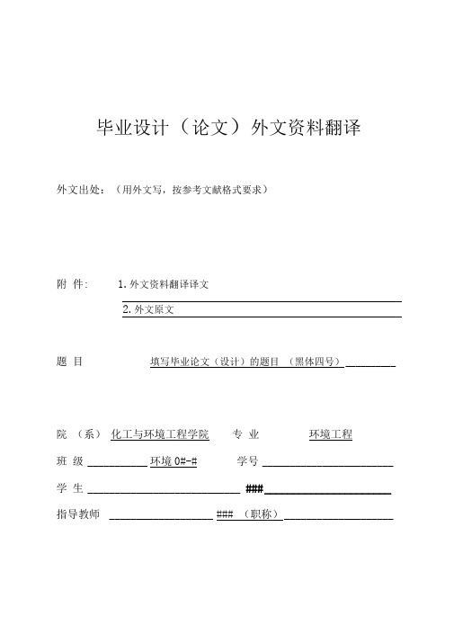
毕业设计
外文出处:(用外文写,按参考文献格式要求)
附 件:1.外文资料翻译译文
2.外文原文
题 目填写毕业论文(设计)的题目 (黑体四号)
院 (系)化工与环境工程学院专 业环境工程
班 级环境0#Байду номын сангаас#学号
学 生###
指导教师###(职称)
附件1:外文资料翻译译文
译文标题 (3号黑体,居中)
(空一行)
xxxxxxxxxxxxxxxxxxxxxxxxxxxxxxxxxxxxxxxxxxxxxxxxxxxxxxxxxxxxxxx
xxxx。…(小4号宋体,1.25倍行距)
附件2:外文原文
6毕业设计(论文)外文译文封面

毕业设计(论文)外文文献译文文献题名:葡萄糖作为单一有机基质强化生物除磷的SBR法Enhanced Biological Phosphorus Removal in SBR UsingGlucose as a Single Organic Substrate学院:环境科学与工程学院专业:环境工程2005级学生姓名:李凯指导教师:胡开林日期:2009年03月31日~06月15日葡萄糖作为单一有机基质强化生物除磷的SBR法蒋轶锋、李相昆、冯晓宇、王树涛、王宝贞、刘亚男、陈建孟摘要:经过对序批式厌氧/好氧反应器( SBR )的调查研究发现,可以提供葡萄糖作为一个单一的有机基质来对生物除磷( EBPR )进行强化。
研究结果表明,EBPR过程中,也可以成功地与葡萄糖发生以外的其他短链脂肪酸( SCFAs )。
高磷释放和聚羟基血凝素( PHA )在厌氧阶段积累时被发现了至关重要的除磷在好氧阶段。
在细胞内测量糖原,其储备显示,其中有较高的机会在厌氧条件下以取代能源作用的聚磷。
此外,还利用糖原进行碳源植物血凝素的合成,以及正如早先的报道所称那样。
然而,所积累的植物血凝素在这个系统主要是以聚羟基( PHV )为形式的,而并不是聚羟基丁酸酯,乳酸作为发酵产品还发现可以被大量的释放。
应用基本知识,生物化学以及实验结果产生一个概念模型,即利用葡萄糖的代谢糖诱导强化EBPR 。
关键词:强化生物除磷( EBPR ),序批式反应器( SBR ),血糖, PHA 1、材料和方法1.1 SBR 工艺操作哈尔滨工学院的控制研究中心在水污染实验室安装了的一个具有规模的 EBPR 系统,并将接种物从中播种。
将集中的有机组成和矿物成分进行的综合废水被用作试验的原水。
为尽量减少基质降解,原料从稀释自来水之前的SBR工艺运行周期中开始准备。
SBR的工作容积为2升,并于操作填充和借鉴的基础上,以8小时周期组成的10分钟灌装或者将其撤消,周期为厌氧2小时,好氧4小时, 1小时和50分钟解决闲置阶段的序列。
