毕设外文翻译(译文)封面
毕业设计中英文翻译【范本模板】
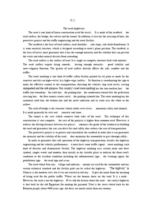
英文The road (highway)The road is one kind of linear construction used for travel。
It is made of the roadbed,the road surface, the bridge, the culvert and the tunnel. In addition, it also has the crossing of lines, the protective project and the traffic engineering and the route facility。
The roadbed is the base of road surface, road shoulder,side slope, side ditch foundations. It is stone material structure, which is designed according to route's plane position .The roadbed, as the base of travel, must guarantee that it has the enough intensity and the stability that can prevent the water and other natural disaster from corroding.The road surface is the surface of road. It is single or complex structure built with mixture。
The road surface require being smooth,having enough intensity,good stability and anti—slippery function. The quality of road surface directly affects the safe, comfort and the traffic。
毕业设计外文翻译译文

1 工程概论1.1 工程专业1.2 工业和技术1.3 现代制造业工程专业1 工程行业是历史上最古老的行业之一。
如果没有在广阔工程领域中应用的那些技术,我们现在的文明绝不会前进。
第一位把岩石凿削成箭和矛的工具匠是现代机械工程师的鼻祖。
那些发现地球上的金属并找到冶炼和使用金属的方法的工匠们是采矿和冶金工程师的先祖。
那些发明了灌溉系统并建造了远古世纪非凡的建筑物的技师是他们那个时代的土木工程师。
2 工程一般被定义为理论科学的实际应用,例如物理和数学。
许多早期的工程设计分支不是基于科学而是经验信息,这些经验信息取决于观察和经历,而不是理论知识。
这是一个倾斜面实际应用的例子,虽然这个概念没有被确切的理解,但是它可以被量化或者数字化的表达出来。
3 从16、17世纪当代初期,量化就已经成为科学知识大爆炸的首要原因之一。
另外一个重要因素是实验法验证理论的发展。
量化包含了把来源于实验的数据和信息转变成确切的数学术语。
这更加强调了数学是现代工程学的语言。
4 从19世纪开始,它的结果的实际而科学的应用已经逐步上升。
机械工程师现在有精确的能力去计算来源于许多不同机构之间错综复杂的相互作用的机械优势。
他拥有能一起工作的既新型又强硬的材料和巨大的新能源。
工业革命开始于使用水和蒸汽一起工作。
从此使用电、汽油和其他能源作动力的机器变得如此广泛以至于它们承担了世界上很大比例的工作。
5 科学知识迅速膨胀的结果之一就是科学和工程专业的数量的增加。
到19世纪末不仅机械、土木、矿业、冶金工程被建立而且更新的化学和电气工程专业出现了。
这种膨胀现象一直持续到现在。
我们现在拥有了核能、石油、航天航空空间以及电气工程等。
每种工程领域之内都有细分。
6 例如,土木工程自身领域之内有如下细分:涉及永久性结构的建筑工程、涉及水或其他液体流动与控制系统的水利工程、涉及供水、净化、排水系统的研究的环境工程。
机械工程主要的细分是工业工程,它涉及的是错综复杂的机械系统,这些系统是工业上的,而非单独的机器。
毕业设计(论文)外文原文及译文
毕业设计(论文)外文原文及译文一、外文原文MCUA microcontroller (or MCU) is a computer-on-a-chip. It is a type of microcontroller emphasizing self-sufficiency and cost-effectiveness, in contrast to a general-purpose microprocessor (the kind used in a PC).With the development of technology and control systems in a wide range of applications, as well as equipment to small and intelligent development, as one of the single-chip high-tech for its small size, powerful, low cost, and other advantages of the use of flexible, show a strong vitality. It is generally better compared to the integrated circuit of anti-interference ability, the environmental temperature and humidity have better adaptability, can be stable under the conditions in the industrial. And single-chip widely used in a variety of instruments and meters, so that intelligent instrumentation and improves their measurement speed and measurement accuracy, to strengthen control functions. In short,with the advent of the information age, traditional single- chip inherent structural weaknesses, so that it show a lot of drawbacks. The speed, scale, performance indicators, such as users increasingly difficult to meet the needs of the development of single-chip chipset, upgrades are faced with new challenges.The Description of AT89S52The AT89S52 is a low-power, high-performance CMOS 8-bit microcontroller with 8K bytes of In-System Programmable Flash memory. The device is manufactured using Atmel's high-density nonvolatile memory technology and is compatible with the industry-standard 80C51 instruction set and pinout. The on-chip Flash allows the program memory to be reprogrammed in-system or by a conventional nonvolatile memory programmer. By combining a versatile 8-bit CPU with In-System Programmable Flash on a monolithic chip, the Atmel AT89S52 is a powerful microcontroller which provides a highly-flexible and cost-effective solution to many embedded control applications.The AT89S52 provides the following standard features: 8K bytes ofFlash, 256 bytes of RAM, 32 I/O lines, Watchdog timer, two data pointers, three 16-bit timer/counters, a six-vector two-level interrupt architecture, a full duplex serial port, on-chip oscillator, and clock circuitry. In addition, the AT89S52 is designed with static logic for operation down to zero frequency and supports two software selectable power saving modes. The Idle Mode stops the CPU while allowing the RAM, timer/counters, serial port, and interrupt system to continue functioning. The Power-down mode saves the RAM contents but freezes the oscillator, disabling all other chip functions until the next interrupt or hardware reset.Features• Compatible with MCS-51® Products• 8K Bytes of In-System Programmable (ISP) Flash Memory– Endurance: 1000 Write/Erase Cycles• 4.0V to 5.5V Operating Range• Fully Static Operation: 0 Hz to 33 MHz• Three-level Program Memory Lock• 256 x 8-bit Internal RAM• 32 Programmable I/O Lines• Three 16-bit Timer/Counters• Eight Interrupt Sources• Full Duplex UART Serial Channel• Low-power Idle and Power-down Modes• Interrupt Recovery from Power-down Mode• Watchdog Timer• Dual Data Pointer• Power-off FlagPin DescriptionVCCSupply voltage.GNDGround.Port 0Port 0 is an 8-bit open drain bidirectional I/O port. As an output port, each pin can sink eight TTL inputs. When 1s are written to port 0 pins, the pins can be used as high-impedance inputs.Port 0 can also be configured to be the multiplexed low-order address/data bus during accesses to external program and data memory. In this mode, P0 has internal pullups.Port 0 also receives the code bytes during Flash programming and outputs the code bytes during program verification. External pullups are required during program verification.Port 1Port 1 is an 8-bit bidirectional I/O port with internal pullups. The Port 1 output buffers can sink/source four TTL inputs. When 1s are written to Port 1 pins, they are pulled high by the internal pullups and can be used as inputs. As inputs, Port 1 pins that are externally being pulled low will source current (IIL) because of the internal pullups.In addition, P1.0 and P1.1 can be configured to be the timer/counter 2 external count input (P1.0/T2) and the timer/counter 2 trigger input (P1.1/T2EX), respectively.Port 1 also receives the low-order address bytes during Flash programming and verification.Port 2Port 2 is an 8-bit bidirectional I/O port with internal pullups. The Port 2 output buffers can sink/source four TTL inputs. When 1s are written to Port 2 pins, they are pulled high by the internal pullups and can be used as inputs. As inputs, Port 2 pins that are externally being pulled low will source current (IIL) because of the internal pullups.Port 2 emits the high-order address byte during fetches from external program memory and during accesses to external data memory that use 16-bit addresses (MOVX @ DPTR). In this application, Port 2 uses strong internal pull-ups when emitting 1s. During accesses to external data memory that use 8-bit addresses (MOVX @ RI), Port 2 emits the contents of the P2 Special Function Register.Port 2 also receives the high-order address bits and some control signals during Flash programming and verification.Port 3Port 3 is an 8-bit bidirectional I/O port with internal pullups. The Port 3 output buffers can sink/source four TTL inputs. When 1s are written to Port 3 pins, they are pulled high by the internal pullups and can be used as inputs. As inputs, Port 3 pins that are externally being pulled low will source current (IIL) because of the pullups.Port 3 also serves the functions of various special features of the AT89S52, as shown in the following table.Port 3 also receives some control signals for Flash programming and verification.RSTReset input. A high on this pin for two machine cycles while the oscillator is running resets the device. This pin drives High for 96 oscillator periods after the Watchdog times out. The DISRTO bit in SFR AUXR (address 8EH) can be used to disable this feature. In the default state of bit DISRTO, the RESET HIGH out feature is enabled.ALE/PROGAddress Latch Enable (ALE) is an output pulse for latching the low byte of the address during accesses to external memory. This pin is also the program pulse input (PROG) during Flash programming.In normal operation, ALE is emitted at a constant rate of 1/6 the oscillator frequency and may be used for external timing or clocking purposes. Note, however, that one ALE pulse is skipped during each access to external data memory.If desired, ALE operation can be disabled by setting bit 0 of SFR location 8EH. With the bit set, ALE is active only during a MOVX or MOVC instruction. Otherwise, the pin is weakly pulled high. Setting the ALE-disable bit has no effect if the microcontroller is in external execution mode.PSENProgram Store Enable (PSEN) is the read strobe to external program memory. When the AT89S52 is executing code from external program memory, PSENis activated twice each machine cycle, except that two PSEN activations are skipped during each access to external data memory.EA/VPPExternal Access Enable. EA must be strapped to GND in order to enable the device to fetch code from external program memory locations starting at 0000H up to FFFFH. Note, however, that if lock bit 1 is programmed, EA will be internally latched on reset. EA should be strapped to VCC for internal program executions.This pin also receives the 12-volt programming enable voltage (VPP) during Flash programming.XTAL1Input to the inverting oscillator amplifier and input to the internal clock operating circuit.XTAL2Output from the inverting oscillator amplifier.Special Function RegistersNote that not all of the addresses are occupied, and unoccupied addresses may not be implemented on the chip. Read accesses to these addresses will in general return random data, and write accesses will have an indeterminate effect.User software should not write 1s to these unlisted locations, since they may be used in future products to invoke new features. In that case, the reset or inactive values of the new bits will always be 0.Timer 2 Registers:Control and status bits are contained in registers T2CON and T2MOD for Timer 2. The register pair (RCAP2H, RCAP2L) are the Capture/Reload registers for Timer 2 in 16-bit capture mode or 16-bit auto-reload mode.Interrupt Registers:The individual interrupt enable bits are in the IE register. Two priorities can be set for each of the six interrupt sources in the IP register.Dual Data Pointer Registers: To facilitate accessing both internal and external data memory, two banks of 16-bit Data Pointer Registers areprovided: DP0 at SFR address locations 82H-83H and DP1 at 84H-85H. Bit DPS = 0 in SFR AUXR1 selects DP0 and DPS = 1 selects DP1. The user should always initialize the DPS bit to the appropriate value before accessing the respective Data Pointer Register.Power Off Flag:The Power Off Flag (POF) is located at bit 4 (PCON.4) in the PCON SFR. POF is set to “1” during power up. It can be set and rest under software control and is not affected by reset.Memory OrganizationMCS-51 devices have a separate address space for Program and Data Memory. Up to 64K bytes each of external Program and Data Memory can be addressed.Program MemoryIf the EA pin is connected to GND, all program fetches are directed to external memory. On the AT89S52, if EA is connected to VCC, program fetches to addresses 0000H through 1FFFH are directed to internal memory and fetches to addresses 2000H through FFFFH are to external memory.Data MemoryThe AT89S52 implements 256 bytes of on-chip RAM. The upper 128 bytes occupy a parallel address space to the Special Function Registers. This means that the upper 128 bytes have the same addresses as the SFR space but are physically separate from SFR space.When an instruction accesses an internal location above address 7FH, the address mode used in the instruction specifies whether the CPU accesses the upper 128 bytes of RAM or the SFR space. Instructions which use direct addressing access of the SFR space. For example, the following direct addressing instruction accesses the SFR at location 0A0H (which is P2).MOV 0A0H, #dataInstructions that use indirect addressing access the upper 128 bytes of RAM. For example, the following indirect addressing instruction, where R0 contains 0A0H, accesses the data byte at address 0A0H, rather than P2 (whose address is 0A0H).MOV @R0, #dataNote that stack operations are examples of indirect addressing, so the upper 128 bytes of data RAM are available as stack space.Timer 0 and 1Timer 0 and Timer 1 in the AT89S52 operate the same way as Timer 0 and Timer 1 in the AT89C51 and AT89C52.Timer 2Timer 2 is a 16-bit Timer/Counter that can operate as either a timer or an event counter. The type of operation is selected by bit C/T2 in the SFR T2CON (shown in Table 2). Timer 2 has three operating modes: capture, auto-reload (up or down counting), and baud rate generator. The modes are selected by bits in T2CON.Timer 2 consists of two 8-bit registers, TH2 and TL2. In the Timer function, the TL2 register is incremented every machine cycle. Since a machine cycle consists of 12 oscillator periods, the count rate is 1/12 of the oscillator frequency.In the Counter function, the register is incremented in response to a1-to-0 transition at its corresponding external input pin, T2. In this function, the external input is sampled during S5P2 of every machine cycle. When the samples show a high in one cycle and a low in the next cycle, the count is incremented. The new count value appears in the register during S3P1 of the cycle following the one in which the transition was detected. Since two machine cycles (24 oscillator periods) are required to recognize a 1-to-0 transition, the maximum count rate is 1/24 of the oscillator frequency. To ensure that a given level is sampled at least once before it changes, the level should be held for at least one full machine cycle.InterruptsThe AT89S52 has a total of six interrupt vectors: two external interrupts (INT0 and INT1), three timer interrupts (Timers 0, 1, and 2), and the serial port interrupt. These interrupts are all shown in Figure 10.Each of these interrupt sources can be individually enabled or disabledby setting or clearing a bit in Special Function Register IE. IE also contains a global disable bit, EA, which disables all interrupts at once.Note that Table 5 shows that bit position IE.6 is unimplemented. In the AT89S52, bit position IE.5 is also unimplemented. User software should not write 1s to these bit positions, since they may be used in future AT89 products. Timer 2 interrupt is generated by the logical OR of bits TF2 and EXF2 in register T2CON. Neither of these flags is cleared by hardware when the service routine is vectored to. In fact, the service routine may have to determine whether it was TF2 or EXF2 that generated the interrupt, and that bit will have to be cleared in software.The Timer 0 and Timer 1 flags, TF0 and TF1, are set at S5P2 of the cycle in which the timers overflow. The values are then polled by the circuitry in the next cycle. However, the Timer 2 flag, TF2, is set at S2P2 and is polled in the same cycle in which the timer overflows.二、译文单片机单片机即微型计算机,是把中央处理器、存储器、定时/计数器、输入输出接口都集成在一块集成电路芯片上的微型计算机。
(完整版)_毕业设计英文翻译_及格式

毕业设计(论文)英文翻译题目专业班级姓名学号指导教师职称200年月日The Restructuring of OrganizationsThroughout the 1990s, mergers and acquisitions a major source of corporate restructuring, affecting millions of workers and their families. This form of restructuring often is accompanied by downsizing. Downsizing is the process of reducing the size of a firm by laying off or retiring workers early. The primary objectives of downsizing are similar in U.S. companies and those in other countries:●cutting cost,●spurring decentralization and speeding up decision making,●cutting bureaucracy and eliminating layers of especially they did five years ago. One consequence of this trend is that today’s managers supervise larger numbers of subordinates who report directly to them. In 1990, only about 20 percent of managers supervise twelve or more people and 54 percent supervised six or fewer.Because of downsizing, first-line managers quality control, resources, and industrial engineering provide guidance and support. First-line managers participate in the production processes and other line activities and coordinate the efforts of the specialists as part of their jobs. At the same time, the workers that first-line managers supervise are less willing to put up with authoritarian management. Employees want their jobs to be more creative, challenging, fun, and satisfying and want to participate in decisions affecting their work. Thus self-managed work teams that bring workers and first-line managers together to make joint decisions to improve the way they do their jobs offer a solution to both supervision and employee expectation problems. When you ’t always the case. Sometimes entire divisions of a firm are simply spun off from the main company to operate on their own as new, autonomous companies. The firm that spun them off may then become one of their most important customers or suppliers. That AT&T “downsized” the old Bell Labs unit, which is now known as Lucent Technologies. Now, rather than - return is free to enter into contracts with companies other than AT&T. this method of downsizing is usually called outsourcing.Outsourcing means letting other organizations perform a needed service andor manufacture needed parts or products. Nike outsources the production of its shoes to low-cost plants in South Korea and China and imports the shoes for distribution in North America. These same plants also ship shoes to Europe and other parts of Asia for distribution. Thus today’s managers face a new challenge: t o plan, organize, lead, and control a company that may as a modular corporation. The modularcorporation is most is most common in three industries: apparel, auto manufacturing, and electronics. The most commonly out-sourced function is production. By out sourcing production, a company can switch supplier best suited to a customer’s needs.Decisions about what to outsource and what to keep in- to contract production to another company is a sound business decision to contract production to another company is a sound business decision, at least for U.S. manufacturers. It appears to the unit cost of production by relieving the company of some overhead, and it frees the company to allocate scarce resources to activities for which the company examples of modular companies are Dell Computer, Nike, Liz Claiborne fashions, and ship designer Cyrix.As organizations downsize and outsource functions, they become flatter and smaller. Unlike the behemoths of the past, the new, smaller firms are less like autonomous fortresses and more like nodes in a net work of complex relationships. This approach, called the network form of organization, involves establishing strategic alliances among several entities.In Japan, cross-ownership and alliances among firms-called keiretsu-both foreign and U.S. auto parts producers. It also owns 49 percent of Hertz, the car rental company that is also a major customer. Other alliances include involvement in several research consortia. In the airline industry, a common type of alliance is between an airline and an airframe manufacture. For example, Delta recently agreed to buy all its aircraft from Boeing. Boeing Airlines. Through these agreements, Boeing guarantees that it will be able to sell specified models of its aircraft and begin to adapt their operations to the models they will be flying in the future. Thus both sides expect to reap benefits from these arrangements for many years.Networks forms of organizations are prevalent in access to the universities and in small, creative organizations. For example, the U.S. biotechnology industry is characterized by network of relationships between new biotechnology firms dedicated to research and new products development and established firms in industries that can use these new products, such as pharmaceuticals. In return for sharing technical information with the larger firms, the smaller firms gain access to their partners’ resources for product testing, marketing, and distribution. Big pharmaceutical firms such as Merk or Eli Lily gain from such partnerships because the smaller firms typically development cycle in the larger firms.Being competitive increasingly requires establishing and managing strategic alliances with other firms. In a strategic alliance, two or more firms agree to cooperate in a venture that is expected to benefit both firms.企业重组整个20世纪90年代中,合并和收购一直是企业重组的主要起源,影响着千百万的工人和他们的家庭。
本科毕业设计外文文献翻译

(Shear wall st ructural design ofh igh-lev el fr ameworkWu Jiche ngAbstract : In t his pape r the basic c oncepts of man pow er from th e fra me sh ear w all str uc ture, analy sis of the struct ur al des ign of th e c ont ent of t he fr ame she ar wall, in cludi ng the seism ic wa ll she ar spa本科毕业设计外文文献翻译学校代码: 10128学 号:题 目:Shear wall structural design of high-level framework 学生姓名: 学 院:土木工程学院 系 别:建筑工程系 专 业:土木工程专业(建筑工程方向) 班 级:土木08-(5)班 指导教师: (副教授)nratiodesign, and a concretestructure in themost co mmonly usedframe shear wallstructurethedesign of p oints to note.Keywords: concrete; frameshearwall structure;high-risebuildingsThe wall is amodern high-rise buildings is an impo rtant buildingcontent, the size of theframe shear wall must comply with building regulations. The principle is that the largersizebut the thicknessmust besmaller geometric featuresshouldbe presented to the plate,the force is close to cylindrical.The wall shear wa ll structure is a flatcomponent. Itsexposure to the force along the plane level of therole ofshear and moment, must also take intoaccountthe vertical pressure.Operate under thecombined action ofbending moments and axial force andshear forcebythe cantilever deep beam under the action of the force levelto loo kinto the bottom mounted on the basis of. Shearwall isdividedinto a whole walland theassociated shear wall in theactual project,a wholewallfor exampl e, such as generalhousingconstruction in the gableor fish bone structure filmwalls and small openingswall.Coupled Shear walls are connected bythecoupling beam shear wall.Butbecause thegeneralcoupling beamstiffness is less thanthe wall stiffnessof the limbs,so. Walllimb aloneis obvious.The central beam of theinflection pointtopay attentionto thewall pressure than the limits of the limb axis. Will forma shortwide beams,widecolumn wall limbshear wall openings toolarge component atbothen ds with just the domain of variable cross-section ro din the internalforcesunder theactionof many Walllimb inflection point Therefore, the calcula tions and construction shouldAccordingtoapproximate the framestructure to consider.The designof shear walls shouldbe based on the characteristics of avariety ofwall itself,and differentmechanical ch aracteristicsand requirements,wall oftheinternalforcedistribution and failuremodes of specific and comprehensive consideration of the design reinforcement and structural measures. Frame shear wall structure design is to consider the structure of the overall analysis for both directionsofthehorizontal and verticaleffects. Obtain theinternal force is required in accordancewiththe bias or partial pull normal section forcecalculation.The wall structure oftheframe shear wall structural design of the content frame high-rise buildings, in the actual projectintheuse of themost seismic walls have sufficient quantitiesto meet thelimitsof the layer displacement, the location isrelatively flexible. Seismic wall for continuous layout,full-length through.Should bedesigned to avoid the wall mutations in limb length and alignment is notupand down the hole. The sametime.The inside of the hole marginscolumnshould not belessthan300mm inordertoguaranteethelengthof the column as the edgeof the component and constraint edgecomponents.Thebi-direc tional lateral force resisting structural form of vertical andhorizontalwallconnected.Each other as the affinityof the shear wall. For one, two seismic frame she ar walls,even beam highratio should notgreaterthan 5 and a height of not less than400mm.Midline columnand beams,wall midline shouldnotbe greater tha nthe columnwidthof1/4,in order toreduce thetorsional effect of the seismicaction onthecolumn.Otherwisecan be taken tostrengthen thestirrupratio inthe column tomake up.If theshear wall shearspan thanthe big two. Eventhe beamcro ss-height ratiogreaterthan 2.5, then the design pressure of thecut shouldnotmakeabig 0.2. However, if the shearwallshear spanratioof less than two couplingbeams span of less than 2.5, then the shear compres sion ratiois notgreater than 0.15. Theother hand,the bottom ofthe frame shear wallstructure to enhance thedesign should notbe less than200mmand notlessthanstorey 1/16,otherpartsshouldnot be less than 160mm and not less thanstorey 1/20. Aroundthe wall of the frame shear wall structure shouldbe set to the beam or dark beamand the side columntoform a border. Horizontal distributionofshear walls can from the shear effect,this design when building higher longeror framestructure reinforcement should be appropriatelyincreased, especially in the sensitiveparts of the beam position or temperature, stiffnesschange is bestappropriately increased, thenconsideration shouldbe givento the wallverticalreinforcement,because it is mainly from the bending effect, andtake in some multi-storeyshearwall structurereinforcedreinforcement rate -likelessconstrained edgeofthecomponent or components reinforcement of theedge component.References: [1 sad Hayashi,He Yaming. On the shortshear wall high-rise buildingdesign [J].Keyuan, 2008, (O2).高层框架剪力墙结构设计吴继成摘要: 本文从框架剪力墙结构设计的基本概念人手, 分析了框架剪力墙的构造设计内容, 包括抗震墙、剪跨比等的设计, 并出混凝土结构中最常用的框架剪力墙结构设计的注意要点。
毕业设计外文资料翻译sc-pdf

毕业设计外文资料翻译题目甲醇氧化生产甲醛的银催化剂改性学院化学化工学院专业化学工程与工艺班级0803学生许继盟学号20080207167指导教师倪献智二〇一二年三月十五日Catalysts Today, 1996, (28): 239-244.甲醇氧化生产甲醛的银催化剂的改性A.N.Pestryakov摘 要 银催化剂的性能可用Zr ,La , Rb ,C s 的氧化物改性,改性后的银催化剂的物化性能和催化性能已在甲醇的选择性氧化工艺中研究过,甲醇氧化制甲醛工艺中,质量分数为1%-10%的改性添加物会改变载体银的有效电荷及氧化还原性能、金属分散度和其表面扩散、催化剂表面酸度及结焦程度。
当银催化性能改变时,改性物主要影响催化剂活性位(++δn Ag Ag)。
关键词 银催化剂;甲醇氧化为甲醛 1 简介甲醇选择性氧化生产甲醛工艺中使用大量的载体银催化剂[1-3]。
采用不同的非有机添加物对银催化剂进行改性是提高其性能的最有前景的方法之一。
在银催化剂发现之后,人们致力于对其进行改进,以达到提高其催化活性和寿命,降低银使用量和扩展其工艺操作条件的目的。
广泛使用载体以减少银使用量及防止银在“严酷”条件(600-700 ℃)下烧结也是改性方法之一。
但是载体的堆积有限,不同改性化合物的少量添加(质量分数0.1-10%)可以使银可变的催化性能产生较大差异。
在科技和专利文献中提到过很多不同的添加物,它们能改善并激发银的催化性能[3-14]。
在这其中,研究人员提到改性作用的不同机理:银上金属的电子功能和电子密度改变[7-9],O 2吸附的差异[3,10],催化剂表面酸度[11],催化剂表面的机械堵塞[12],添加物的固有催化性质[13,14]。
然而,所有这些仅描述了催化剂改性的几个分散的方面,并没有涉及添加物对银催化剂改性影响的差异。
也没有考虑改性物对银催化剂活性位电子状态的影响。
在本文中,我们研究了改性物对银的性能影响的几个方面[15-18],目的是在甲醇氧化制甲醛工艺中对稀有和稀土金属氧化物反应及银催化剂的电子属性、物化属性和催化属性进行综合研究。
毕业设计(论文)外文资料翻译【范本模板】
南京理工大学紫金学院毕业设计(论文)外文资料翻译系:机械系专业:车辆工程专业姓名:宋磊春学号:070102234外文出处:EDU_E_CAT_VBA_FF_V5R9(用外文写)附件:1。
外文资料翻译译文;2.外文原文.附件1:外文资料翻译译文CATIA V5 的自动化CATIA V5的自动化和脚本:在NT 和Unix上:脚本允许你用宏指令以非常简单的方式计划CATIA。
CATIA 使用在MS –VBScript中(V5.x中在NT和UNIX3。
0 )的共用部分来使得在两个平台上运行相同的宏。
在NT 平台上:自动化允许CATIA像Word/Excel或者Visual Basic程序那样与其他外用分享目标。
ATIA 能使用Word/Excel对象就像Word/Excel能使用CATIA 对象。
在Unix 平台上:CATIA将来的版本将允许从Java分享它的对象。
这将提供在Unix 和NT 之间的一个完美兼容。
CATIA V5 自动化:介绍(仅限NT)自动化允许在几个进程之间的联系:CATIA V5 在NT 上:接口COM:Visual Basic 脚本(对宏来说),Visual Basic 为应用(适合前:Word/Excel ),Visual Basic。
COM(零部件目标模型)是“微软“标准于几个应用程序之间的共享对象。
Automation 是一种“微软“技术,它使用一种解释环境中的COM对象。
ActiveX 组成部分是“微软“标准于几个应用程序之间的共享对象,即使在解释环境里。
OLE(对象的链接与嵌入)意思是资料可以在一个其他应用OLE的资料里连结并且可以被编辑的方法(在适当的位置编辑).在VBScript,VBA和Visual Basic之间的差别:Visual Basic(VB)是全部的版本。
它能产生独立的计划,它也能建立ActiveX 和服务器。
它可以被编辑。
VB中提供了一个补充文件名为“在线丛书“(VB的5。
毕业设计外文翻译
毕业设计外文翻译Newly compiled on November 23, 2020Title:ADDRESSING PROCESS PLANNING AND VERIFICATION ISSUES WITH MTCONNECTAuthor:Vijayaraghavan, Athulan, UC BerkeleyDornfeld, David, UC BerkeleyPublication Date:06-01-2009Series:Precision Manufacturing GroupPermalink:Keywords:Process planning verification, machine tool interoperability, MTConnect Abstract:Robust interoperability methods are needed in manufacturing systems to implement computeraided process planning algorithms and to verify their effectiveness. In this paper wediscuss applying MTConnect, an open-source standard for data exchange in manufacturingsystems, in addressing two specific issues in process planning and verification. We use data froman MTConnect-compliant machine tool to estimate the cycle time required for machining complexparts in that machine. MTConnect data is also used in verifying the conformance of toolpaths tothe required part features by comparing the features created by the actual tool positions to therequired part features using CAD tools. We demonstrate the capabilities of MTConnect in easilyenabling process planning and verification in an industrial environment.Copyright Information:All rights reserved unless otherwise indicated. Contact the author or original publisher for anynecessary permissions. eScholarship is not the copyright owner for deposited works. Learn moreADDRESSING PROCESS PLANNING AND VERIFICATION ISSUESWITH MTCONNECTAthulan Vijayaraghavan, Lucie Huet, and David DornfeldDepartment of Mechanical EngineeringUniversity of CaliforniaBerkeley, CA 94720-1740William SobelArtisanal SoftwareOakland, CA 94611Bill Blomquist and Mark ConleyRemmele Engineering Inc.Big Lake, MNKEYWORDSProcess planning verification, machine tool interoperability, MTConnect.ABSTRACTRobust interoperability methods are needed in manufacturing systems to implement computeraided process planning algorithms and to verifytheir effectiveness. In this paper we discuss applying MTConnect, an open-source standardfor data exchange in manufacturing systems, in addressing two specific issues in processplanning and verification. We use data from an MTConnect-compliant machine tool to estimatethe cycle time required for machining complex parts in that machine. MTConnect data is also used in verifying the conformance of toolpaths to the required part features by comparing the features created by the actual tool positions tothe required part features using CAD tools. We demonstrate the capabilities of MTConnect in easily enabling process planning and verificationin an industrial environment.INTRODUCTIONAutomated process planning methods are acritical component in the design and planning of manufacturing processes for complex parts. Thisis especially the case with high speed machining, as the complex interactions betweenthe tool and the workpiece necessitates careful selection of the process parameters and the toolpath design. However, to improve the effectiveness of these methods, they need to be integrated tightly with machines and systems in industrial environments. To enable this, we need robust interoperability standards for data exchange between the different entities in manufacturing systems.In this paper, we discuss using MTConnect – an open source standard for data exchange in manufacturing systems – to address issues in process planning and verification in machining.We discuss two examples of using MTConnect for better process planning: in estimating the cycle time for high speed machining, and in verifying the effectiveness of toolpath planning for machining complex features. As MTConnect standardizes the exchange of manufacturing process data, process planning applications can be developed independent of the specific equipment used (Vijayaraghavan, 2008). This allowed us to develop the process planning applications and implement them in an industrial setting with minimal overhead. The experiments discussed in this paper were developed at UC Berkeley and implemented at Remmele Engineering Inc.The next section presents a brief introduction to MTConnect, highlighting its applicability in manufacturing process monitoring. We then discuss two applications of MTConnect – in computing cycle time estimates and in verifying toolpath planning effectiveness. MTCONNECTMTConnect is an open software standard for data exchange and communication between manufacturing equipment (MTConnect, 2008a). The MTConnect protocol defines a common language and structure for communication in manufacturing equipment, and enables interoperability by allowing access to manufacturing data using standardized interfaces. MTConnect does not define methods for data transmission or use, and is not intended to replace the functionality of existing products and/or data standards. It enhances the data acquisition capabiltiies of devices and applications, moving towards a plug-and-play environment that can reduce the cost of integration. MTConnect is built upon prevalent standards in the manufacturing and software industry, which maximizes the number of tools available for its implementation and provides a high level of interoperability with other standards and tools in these industries.MTConnect is an XML-based standard andmessages are encoded using XML (eXtensibleMarkup Language), which has been usedextensively as a portable way of specifying data interchange formats (W3C, 2008). A machinereadable XML schema defines the format ofMTConnect messages and how the data itemswithin those messages are represented. At thetime of publication, the latest version of the MTConnect standard defining the schema is (MTConnect, 2008b).The MTConnect protocol includes the following information about a device:Identity of a deviceIdentity of all the independent components ofthe deviceDesign characteristics of the deviceData occurring in real or near real-time by thedevice that can be utilized by other devices or applications. The types of data that can beaddressed includes:Physical and actual device design dataMeasurement or calibration dataNear-real time data from the deviceFigure 1 shows an example of a data gatheringsetup using MTConnect. Data is gathered innear-time from a machine tool and from thermal sensors attached to it. The data stored by the MTConnect protocol for this setup is shown inTable 1. Specialized adaptors are used to parsethe data from the machine tool and from thesensor devices into a format that can beunderstood by the MTConnect agent, which inturn organizes the data into the MTConnect XML schema. Software tools can be developed which operate on the XML data from the agent. Sincethe XML schema is standardized, the softwaretools can be blind to the specific configuration ofthe equipment from where the data is gathered. FIGURE 1: MTCONNECT SETUP.TABLE 1:MTCONNECT PROTOCOL INFORMATION FOR MACHINE TOOL IN FIGURE 1.Device identity “3-Axis Milling Machine”Devicecomponents1 X Axis; 1 Y Axis; 1 Z Axis;2 Thermal SensorsDevice designcharacteristicsX Axis Travel: 6”Y Axis Travel: 6”Z Axis Travel: 12”Max Spindle RPM: 24000Data occurringin deviceTool position: (0,0,0);Spindle RPM: 1000Alarm Status: OFFTemp Sensor 1: 90oFTemp Sensor 2: 120oFAn added benefit of XML is that it is a hierarchical representation, and this is exploited by designing the hierarchy of the MTConnect schema to resemble that of a conventional machine tool. The schema itself functions as a metaphor for the machine tool and makes the parsing and encoding of messages intuitive. Data items are grouped based on their logical organization, and not on their physical organization. For example, Figure 2 shows the XML schema associated with the setup shown in Figure 1. Although the temperature sensors operate independant of the machine tool (with its own adaptor), the data from the sensors are associated with specific components of the machine tool, and hence the temperature data is a member of the hierarchy of the machine tool. The next section discusses applying MTConnect in estimating cycle time in high-speed machining.ACCURATE CYCLE TIME ESTIMATESIn high speed machining processes there can be discrepancies between the actual feedrates during cutting and the required (or commanded) feedrates. These discrepancies are dependenton the design of the controller used in the machine tool and the toolpath geometry. While there have been innovative controller designs that minimize the feedrate discrepancy (Sencer,2008), most machine tools used in conventional industrial facilities have commercial off-the-shelf controllers that demonstrate some discrepancies in the feedrates, especially when machining complex geometries at high speeds. There is a need for simple tools to estimate the discrepancy in these machining conditions. Apart from influencing the surface quality of the machined parts, feedrate variation can lead to inaccurate estimates of the cycle time during machining. Accurate estimates of the cycle time is a critical requirement in planning for complex machining operations in manufacturing facilities. The cycle time is needed for both scheduling the part in a job shop, as well as for costing the part. Inaccurate cycle time estimates (especiallywhen the feed is overestimated) can lead to uncompetitive estimates for the cost of the part and unrealistic estimates for the cycle time. Related Workde Souza and Coelho (2007) presented a comprehensive set of experiments to demonstrate feedrate limitations during the machining of freeform surfaces. They identified the causes of feedrate variation as dynamic limitations of the machine, block processing time FIGURE 2: MTCONNECT HIERARCHY.for the CNC, and the feature size in the toolpaths. Significant discrepancies were observed between the actual and commanded feeds when machining with linear interpolation (G01). The authors used a custom monitoring and data logging system to capture the feedrate variation in the CNC controller during machining. Sencer et al. (2008) presented feed scheduling algorithms to minimize the machining time for 5- axis contour machining of sculptured surfaces. The algorithm optimized the profile of the feedrate for minimum machining time, while observing constrains on the smoothness of the feedrate, acceleration and jerk of the machine tool drives. This follows earlier work in minimizing the machining time in 3-axis milling using similar feed scheduling techniques(Altintas, 2003). While these methods are very effective in improving the cycle time of complex machining operations, they can be difficult toapply in conventional factory environments asthey require specialized control systems. The methods we discuss in this paper do notaddress the optimization of cycle time during machining. Instead, we provide simple tools to estimate the discrepancy in feedrates during machining and use this in estimating the cycletime for arbitrary parts.MethodologyDuring G01 linear interpolation the chief determinant of the maximum feedrateachievable is the spacing between adjacentpoints (G01 step size). We focus on G01 interpolation as this is used extensively when machining simultaneously in 3 or more axes.The cycle time for this machine tool to machinean arbitrary part (using linear interpolation) is estimated based on the maximum feedachievable by the machine tool at a given path spacing. MTConnect is a key enabler in this process as it standardizes both data collectionas well as the analysis.The maximum feedrate achievable is estimated using a standardized test G-code program. This program consists of machining a simple shapewith progressively varying G01 path spacings.The program is executed on an MTConnectcompliant machine tool, and the position andfeed data from the machine tool is logged innear-real time. The feedrate during cutting at the different spacings is then analyzed, and amachine tool “calibration” curve is developed, which identifies the maximum feedrate possibleat a given path spacing.FIGURE 3: METHODOLOGY FOR ESTIMATING CYCLE TIME.Conventionally, the cycle time for a giventoolpath is estimated by summing the time takenfor the machine tool to process each block of Gcode, which is calculated as the distancetravelled in that block divided by the feedrate ofthe block. For a given arbitrary part G-code to be executed on a machine tool, the cycle time is estimated using the calibration curve as follows. For each G01 block executed in the program, the size of the step is calculated (this is the distance between the points the machine tool is interpolating) and the maximum feedrate possible at this step size is looked up from the calibration curve. If the maximum feedrate is smaller than the commanded feedrate, this line of the G-code is modified to machine at the (lower) actual feedrate, if the maximum feedrate is greater, then the line is left unmodified. This is performed for all G01 lines in the program, and finally, the cycle time of the modified G-code program is estimated the conventional way. This methodology is shown in Figure 3. The next section discusses an example applying this methodology on a machine tool.ResultsWe implemented the cycle time estimation method on a 3-axis machine tool with a conventional controller. The calibration curve of this machine tool was computed by machining a simple circular feature at the following linear spacings: ”, ”, ”, ”,”, ”, ”, ”, ”. Weconfirmed that the radius of the circle (that is, the curvature in the toolpath) had no effect on the feedrate achieved by testing with circular features of radius ”, ”, and ”, andobserving the same maximum feedrate in all cases. Table 2 shows the maximum achievable feedrate at each path spacing when using a circle of radius 1”. We can see from the table that the maximum feedrate achievable is a linear function of the path spacing. Using a linear fit, the calibration curve for this machine tool can be estimated. Figure 4 plots the calibration curve for this machine tool. The relationship between the feedrate and the path spacing is linear asthe block processing time of the machine tool controller is constant at all feedrates. The block processing time determines the maximumfederate achievable for a given spacing as it isthe time the machine tool takes to interpolateone block of G-code. As the path spacing (or interpolatory distance) linearly increases, thespeed at which it can be interpolated alsoincreases linearly. The relationship for the datain Figure 4 is:MAX FEED (in/min) = 14847 * SPACING (in)TABLE 2: MAXIMUM ACHIEVABLE FEEDRATE AT VARYING PATH SPACINGSpacing Maximum Feedrate”””””””””We also noticed that the maximum feedrate for agiven spacing was unaffected by thecommanded feedrate, as long as it was lesserthan the commanded feedrate. This means thatit was adequate to compute the calibration curveby commanding the maximum possible feedratein the machine tool.FIGURE 4: CALIBRATION CURVE FOR MACHINE TOOL.Using this calibration curve, we estimated thecycle time for machining an arbitrary feature inthis machine tool. The feature we used was a3D spiral with a smoothly varying path spacing,which is shown in Figure 5. The spiral path isdescribed exclusively using G01 steps andinvolves simultaneous 3-axis interpolation. Thepath spacing of the G-code blocks for thefeature is shown in Figure 6.FIGURE 5: 3D SPIRAL FEATURE.FIGURE 6: PATH SPACING VARIATION WITH GCODE LINE FOR SPIRAL FEATURE.Figure 7 shows the predicted feedrate based onthe calibration curve for machining the spiralshape at 100 inches/min, compared to the actualfeedrate during machining. We can see that the feedrate predicted by the calibration curvematches very closely with the actual feedrate.We can also observe the linear relationship between path spacing and maximum feedrate by comparing figures 6 and 7.FIGURE 7: PREDICTED FEEDRATE COMPARED TO MEASURED FEEDRATE FOR SPIRAL FEATURE AT 100 IN/MIN.FIGURE 8: ACTUAL CYCLE TIME TO MACHINE SPIRAL FEATURE AT DIFFERENT FEEDRATES. The cycle time for machining the spiral atdifferent commanded feedrates was alsoestimated using the calibration curve. Figure 8 shows the actual cycle time taken to machinethe spiral feature at different feedrates. Noticehere that the trend is non-linear – an increase infeed does not yield a proportional decrease incycle time – implying that there is somefeedrate discrepancy at high feeds. Figure 9 compares the theoretical cycle time to machineat different feedrates to the actual cycle time andthe model predicted cycle time. We can see thatthe model predictions match the cycle times very closely (within 1%). Significant discrepancies are seen between the theoretical cycle time and the actual cycle time when machining at high feed rates. These discrepancies can be explained bythe difference between the block processingtime for the controller, and the time spent oneach block of G-Code during machining. At high feedrates, the time spent at each block is shorterthan the block processing time, so the controller slows down the interpolation resulting in a discrepancy in the cycle time.These results demonstrated the effectiveness of using the calibration curve to estimate feed, and ultimately apply in estimating the cycle time.This method can be extrapolated to multi-axis machining by measuring the feedrate variationfor linear interpolation in specific axes. We canalso specifically correlate feed in one axis to the path spacing instead of the overall feedrate. FIGURE 9: ACTUAL OBSERVED CYCLE TIMESAND PREDICTED CYCLE TIMES COMPARED TO THE NORMALIZED THEORETICAL CYCLE TIMES FOR MACHINING SPIRAL FEATURE AT DIFFERENT FEEDRATES.TOOL POSITION VERIFICATIONMTConnect data can also be used in verifying toolpath planning for the machining of complex parts. Toolpaths for machining complex featuresare usually designed using specialized CAM algorithms, and traditionally the effectiveness ofthe toolpaths in creating the required partfeatures are either verified using computer simulations of the toolpath, or by surfacemetrology of the machined part. The formerapproach is not very accurate, as the toolpath commanded to the machine tool may not matchthe actual toolpath travelled during machining.The latter approach, while accurate, tends to betime consuming and expensive, and requires the analysis and processing of 3D metrology data(which can be complex). Moreover, errors in the features of a machined part are not solely due to toolpath errors, and using metrology data fortoolpath verification may obfuscate toolpatherrors with process dynamics errors. In aprevious work we discussed a simple way toverify toolpath planning by overlaying the actualtool positions against the CAM generated tool positions (Vijayaraghavan, 2008). We nowdiscuss a more intuitive method to verify the effectiveness of machining toolpaths, wheredata from MTConnect-compliant machine toolsis used to create a solid model of the machined features to compare with the desired features.Related WorkThe manufacturing community has focussed extensively on developing process planning algorithms for the machining of complex parts.Elber (1995) in one of the earliest works in thefield, discussed algorithms for toolpathgeneration for 3- and 5-axis machining. Wrightet al. (2004) discussed toolpath generationalgorithms for the finish machining of freeform surfaces; the algorithms were based on thegeometric properties of the surface features. Vijayaraghavan et al. (2009) discussed methodsto vary the spacing of raster toolpaths and tooptimize the orientation of workpieces infreeform surface machining. The efficiency ofthese methods were validated primarily bymetrology and testing of the machined part. MethodologyTo verify toolpath planning effectiveness, we logthe actual cutting tool positions during machiningfrom an MTConnect-compliant machine tool,and use the positions to generate a solid modelof the machined part. The discrepancy infeatures traced by the actual toolpath relative tothe required part features can be computed by comparing these two solid models. The solidmodel of the machined part from the toolpositions can be obtained as follows:Create a 3D model of the toolCreate a 3D model of the stock materialCompute the swept volume of the tool as ittraces the tool positions (using logged data)Subtract the swept volume of the tool from thestock materialThe remaining volume of material is a solidmodel of the actual machined part.The two models can then be compared using 3D boolean difference (or subtraction) operations.ResultsWe implemented this verification scheme bylogging the cutter positions from an MTConnectcompliant 5-axis machine tool. The procedure toobtain the solid model using the tool positionswas implemented in Vericut. The two modelswere compared using a boolean diff operation in Vericut, which identified the regions in the actual machined part that were different from therequired solid model. An example applying thismethod for a feature is shown in Figure 10.FIGURE 10: A – SOLID MODEL OF REQUIRED PART; B – SOLID MODEL OF PART FROM TOOL POSITIONS SHOWING DISCREPANCIES BETWEEN ACTUAL PART FEATURES AND REQUIRED PART FEATURES. SHADED REGIONSDENOTE ~” DIFFERENCE IN MATERIAL REMOVAL.DISCUSSION AND CONCLUSIONS MTConnect makes it very easy to standardize data capture from disparate sources anddevelop common planning and verification applications. The importance of standardization cannot be overstated here – while it has always been possible to get process data from machine tools, this can be generally cumbersome andtime consuming because different machine tools require different methods of accessing data.Data analysis was also challenging to standardize as the data came in differentformats and custom subroutines were needed to process and analyze data from differentmachine tools. With MTConnect the data gathering and analysis process is standardized resulting in significant cost and time savings. This allowed us to develop the verification tools independent of the machine tools they were applied in. This also allowed us to rapidly deploy these tools in an industrial environment without any overheads (especially from the machine tool sitting idle). The toolpath verification was performed with minimal user intervention on a machine which was being actively used in a factory. The only setup needed was to initially configure the machine tool to output MTConnect-compliant data; since this is a onetime activity, it has an almost negligible impacton the long term utilization of the machine tool. Successful implementations of data capture and analysis applications over MTConnect requires a robust characterization of the data capture rates and the latency in the streaming information. Current implementations of MTConnect are over ethernet, and a data rate of about 10~100Hzwas observed in normal conditions (with no network congestion). While this is adequate for geometric analysis (such as the examples in this paper), it is not adequate for real-time process monitoring applications, such as sensor data logging. More work is needed in developing theMTConnect software libraries so that acceptable data rates and latencies can be achieved.One of the benefits of MTConnect is that it can act as a bridge between academic research and industrial practice. Researchers can developtools that operate on standardized data, whichare no longer encumbered by specific data formats and requirements. The tools can then be easily applied in industrial settings, as the framework required to implement the tools in a specific machine or system is already in place. Greater use of interoperability standards by the academic community in manufacturing research will lead to faster dissemination of research results and closer collaboration with industry. ACKNOWLEDGEMENTSWe thank the reviewers for their valuable comments. MTConnect is supported by AMT –The Association for Manufacturing Technology. We thank Armando Fox from the RAD Lab at UC Berkeley, and Paul Warndorf from AMT for their input. Research at UC Berkeley is supported by the Machine Tool Technology Research Foundation and the industrial affiliates of the Laboratory for Manufacturing and Sustainability. To learn more about the lab’s REFERENCESAltintas, Y., and Erkormaz, K., 2003, “Feedrate Optimization for Spline Interpolation In High Speed Machine Tools”, CIRP Annals –Manufacturing Technology, 52(1), pp. 297-302. de Souza, A. F., and Coelho, R. T., 2007, “Experimental Inv estigation of Feedrate Limitations on High Speed Milling Aimed at Industrial Applications”, Int. J. of Afv. Manuf. Tech, 32(11), pp. 1104–1114.Elber, G., 1995, “Freeform Surface Region Optimization for 3-Axis and 5-Axis Milling”, Computer-Aided Design, 27(6), pp. 465–470. MTConnectTM, 2008b, MTConnectTM Standard, Sencer, B., Altintas, Y., and Croft, E., 2008, “Feed Optimization for Five-axis CNC Machine Tools with Drive Constraints”, Int. J. of Mach.Tools and Manuf., 48(7), pp. 733–745. Vijayaraghavan, A., Sobel, W., Fox, A., Warndorf, P., Dornfeld, D. A., 2008, “Improving Machine Tool Interoperability with Standardized Interface Protocols”, Proceedings of ISFA. Vijayaraghavan, A., Hoover, A., Hartnett, J., and Dornfeld, D. A., 2009, “Improving Endmilli ng Surface Finish by Workpiece Rotation and Adaptive Toolpath Spacing”, Int. J. of Mach. Tools and Manuf., 49(1), pp. 89–98.World Wide Web Consortium (W3C), 2008, “Extensible Markup Language (XML),”Wright, P. K., Dornfeld, D. A., Sundararajan, V., and Misra, D., 2004, “Tool Path Generation for Finish Machining of Freeform Surfaces in the Cybercut Process Planning Pipeline”, Trans. of NAMRI/SME, 32, 159–166.毕业设计外文翻译网址。
6、毕业设计(论文)外文翻译(原文)模板
编号:桂林电子科技大学信息科技学院毕业设计(论文)外文翻译(原文)系(部):专业:学生姓名:学号:指导教师单位:姓名:职称:年月日1、所填写内容“居中”对齐,注意每项下划线长度一致,所填字体为三号字、宋体字。
2、A4纸打印;页边距要求如下:页边距上下各为2.5 厘米,左右边距各为2.5厘米。
正文:要求为小四号Times New Roman字体,行间距取固定值(设置值为20磅);字符间距为默认值(缩放100%,间距:标准)。
页眉处“共X页”,X需要手动修改。
大功率LED散热的研究摘要:如何提高大功率LED的散热能力,是LED器件封装和器件应用设计要解决的核心问题。
介绍并分析了国内外大功率LED散热封装技术的研究现状,总结了其发展趋势与前景用途。
关键词:大功率LED;散热;封装1. 引言发光二极管(LED )诞生至今,已经实现了全彩化和高亮度化,并在蓝光LED 和紫光LED 的基础上开发了白光LED ,它为人类照明史又带来了一次飞跃。
发光二极管(LED)具有低耗能、省电、寿命长、耐用等优点,因而被各方看好将取代传统照明成为未来照明光源。
而大功率LED 作为第四代电光源,赋有“绿色照明光源”之称,具有体积小、安全低电压、寿命长、电光转换效率高、响应速度快、节能、环保等优良特性,必将取代传统的白炽灯、卤钨灯和荧光灯而成为21世纪的新一代光源。
普通LED 功率一般为0.05W ,工作电流为20mA ,大功率LED可以达到1W,2W,甚至数十瓦!工作电流可以是几十毫安到几百毫安不等。
其特点具有体积小、耗电小、发热小、寿命长、响应速度快、安全低电压、耐候性好、方向性好等优点。
外罩可用PC管制作,耐高温达135 度,低温-45 度。
广泛应用在油田、石化、铁路、矿山、部队等特殊行业、舞台装饰、城市景观照明、显示屏以及体育场馆等,特种工作灯具中的具有广泛的应用前景。
但由于目前大功率白光LED 的转换效率还较低,光通量较小,成本较高等方面因素的制约,因此大功率白光LED 短期内的应用主要是一些特殊领域的特种工作灯具,中长期目标才能是通用照明领域。
毕业设计(论文)外文翻译(原文)
毕业设计(论文)——外文翻译(原文)NEW APPLICATION OF DA TABASERelational databases have been in use for over two decades. A large portion of the applications of relational databases have been in the commercial world, supporting such tasks as transaction processing for banks and stock exchanges, sales and reservations for a variety of businesses, and inventory and payroll for almost of all companies. We study several new applications, which have become increasingly important in recent years.First. Decision-support systemAs the online availability of data has grown, businesses have begun to exploit the available data to make better decisions about increase sales. We can extract much information for decision support by using simple SQL queries. Recently however, people have felt the need for better decision support based on data analysis and data mining, or knowledge discovery, using data from a variety of sources.Database applications can be broadly classified into transaction processing and decision support. Transaction-processing systems are widely used today, and companies have accumulated a vast amount of information generated by these systems.The term data mining refers loosely to finding relevant information, or “discovering knowledge,”from a large volume of data. Like knowledge discovery in artificial intelligence, data mining attempts to discover statistical rules and patterns automatically from data. However, data mining differs from machine learning in that it deals with large volumes of data, stored primarily on disk.Knowledge discovered from a database can be represented by a set of rules. We can discover rules from database using one of two models:In the first model, the user is involved directly in the process of knowledge discovery.In the second model, the system is responsible for automatically discovering knowledge from the database, by detecting patterns and correlations in the data.Work on automatic discovery of rules has been influenced strongly by work in the artificial-intelligence community on machine learning. The main differences lie in the volume of data handled in databases, and in the need to access disk. Specialized data-mining algorithms have been developed to handle large volumes of disk-resident data efficiently.The manner in which rules are discovered depends on the class of data-mining application. We illustrate rule discovery using two application classes: classification and associations.Second. Spatial and Geographic DatabasesSpatial databases store information related to spatial locations, and provide support for efficient querying and indexing based on spatial locations. Two types of spatial databases are particularly important:Design databases, or computer-aided-design (CAD) databases, are spatial databases used to store design information about how objects---such as buildings, cars or aircraft---are constructed. Other important examples of computer-aided-design databases are integrated-circuit and electronic-device layouts.Geographic databases are spatial databases used to store geographic information, such as maps. Geographic databases are often called geographic information systems.Geographic data are spatial in nature, but differ from design data in certain ways. Maps and satellite images are typical examples of geographic data. Maps may provide not only location information -suchas boundaries, rivers and roads---but also much more detailed information associated with locations, such as elevation, soil type, land usage, and annual rainfall.Geographic data can be categorized into two types: raster data (such data consist a bit maps or pixel maps, in two or more dimensions.), vector data (vector data are constructed from basic geographic objects). Map data are often represented in vector format.Third. Multimedia DatabasesRecently, there has been much interest in databases that store multimedia data, such as images, audio, and video. Today multimedia data typically are stored outside the database, in files systems. When the number of multimedia objects is relatively small, features provided by databases are usually not important. Database functionality becomes important when the number of multimedia objects stored is large. Issues such as transactional updates, querying facilities, and indexing then become important. Multimedia objects often have descriptive attributes, such as those indicating when they were created, who created them, and to what category they belong. One approach to building a database for such multimedia objects is to use database for storing the descriptive attributes, and for keeping track of the files in which the multimedia objects are stored.However, storing multimedia outside the database makes it harder to provide database functionality, such as indexing on the basis of actual multimedia data content. It can also lead to inconsistencies, such a file that is noted in the database, but whose contents are missing, or vice versa. It is therefore desirable to store the data themselves in the database.Forth. Mobility and Personal DatabasesLarge-scale commercial databases have traditionally been stored in central computing facilities. In the case of distributed database applications, there has usually been strong central database and network administration. Two technology trends have combined to create applications in which this assumption of central control and administration is not entirely correct:1.The increasingly widespread use of personal computers, and, more important, of laptop or “notebook” computers.2.The development of a relatively low-cost wireless digital communication infrastructure, base on wireless local-area networks, cellular digital packet networks, and other technologies.Wireless computing creates a situation where machines no longer have fixed locations and network addresses. This complicates query processing, since it becomes difficult to determine the optimal location at which to materialize the result of a query. In some cases, the location of the user is a parameter of the query. A example is a traveler’s information system that provides data on hotels, roadside services, and the like to motorists. Queries about services that are ahead on the current route must be processed based on knowledge of the user’s location, direction of motion, and speed.Energy (battery power) is a scarce resource for mobile computers. This limitation influences many aspects of system design. Among the more interesting consequences of the need for energy efficiency is the use of scheduled data broadcasts to reduce the need for mobile system to transmit queries. Increasingly amounts of data may reside on machines administered by users, rather than by database administrators. Furthermore, these machines may, at times, be disconnected from the network.SummaryDecision-support systems are gaining importance, as companies realize the value of the on-line data collected by their on-line transaction-processing systems. Proposed extensions to SQL, such as the cube operation, help to support generation of summary data. Data mining seeks to discoverknowledge automatically, in the form of statistical rules and patterns from large databases. Data visualization systems help humans to discover such knowledge visually.Spatial databases are finding increasing use today to store computer-aided design data as well as geographic data. Design data are stored primarily as vector data; geographic data consist of a combination of vector and raster data.Multimedia databases are growing in importance. Issues such as similarity-based retrieval and delivery of data at guaranteed rates are topics of current research.Mobile computing systems have become common, leading to interest in database systems that can run on such systems. Query processing in such systems may involve lookups on server database.毕业设计(论文)——外文翻译(译文)数据库的新应用我们使用关系数据库已经有20多年了,关系数据库应用中有很大一部分都用于商业领域支持诸如银行和证券交易所的事务处理、各种业务的销售和预约,以及几乎所有公司都需要的财产目录和工资单管理。