P11C68-35CG中文资料
GMCC往复式压缩机产品手册说明书

RECIP COMPRESSOR 2020 Array往复式压缩机产品手册12144749我们的企业CompanyGREEN MILE 绿色里程1995年09月 公司成立Sep 1995, Company establishment 1996年10月X1C、X2C系列压缩机开始投产Oct 1996,X1C,X2C seriesrotary comp.2004年03月顺德容桂基地正式投产Mar 2004, Ronggui plant wentinto production2007年11月高效G1系列产品量产成功Nov 2007,High-efficiencyG1 series comp.2008年11月安徽合肥制冷基地投产2008年12月R410A冷媒双缸直流变频产品实现量产Dec 2008, R410A DCinverter twin cylinder comp.2000年10月交流变频机种研发成功实现量产Oct 2000, AC invertercomp.2003年09月R410A直流变频压缩机研发成功实现量产Sep 2003, R410A DCinverter comp.Nov 2008, Hefei plantwent into production2009年12月R134a热泵热水器专用压缩机投放市场Dec 2009, Special comp. forHP water heater in R134a2011年10月安徽芜湖空压基地投产Oct 2011, Wuhu plantwas put into production2011年11月2010年01月卧式系列冷冻压缩机研发成功,投入市场Jan 2010, Horizontalrefrigerating comp.2010年05月CO 热泵热水器专用压缩机研发成功May 2010, Comp. for HPwater heater in CO2010年06月第一亿台旋转式压缩机下线June 2010, The 100 millionthA/C compressor roll-out2010年10月双缸变容压缩机研发成功投入市场Oct 2010, Twin cylindervariable capacity comp.2012年07月2013年09月喷气增焓旋转式变频压缩机研发成功Sep 2013, Gas-injectioninverter comp.2013年09月第2亿台空调压缩机下线Sep 2013, The 200 millionthA/C compressor offline2014年全球市场占有率达30%In 2014, Market shareup to 30%2015年荣获2015年度广东省政府质量奖In 2015, Won theGuangdong QualityAward2016年11月独立压缩机研发成功并正式发布Nov 2016,I-CCC comp.2016年荣获2016年度安徽省质量奖In 2016, Won the AnhuiQuality Award2017年05月欧洲研发中心成立May 2017,EuropeanR&D centerestablishment签约为联合国蒙特利尔R290压缩机示范线Nov 2011, The UN MontrealR290 compressordemonstration line第3000万台变频压缩机下线July 2012,The 30 millionthDC inverter compressorroll-out2018年4月喷气变频热泵采暖专用压缩机正式发布Apr 2018,Heat pump heatingcomp. with EVI.2018年10月“V致能”小型变频空调压缩机研发成功并发布Oct 2018Miniaturized DCinverter comp.日本研发中心成立Japan R&D centerestablishment2019年第五亿台空调压缩机下线The 500 millionthA/C compressorroll-out0405在绿色节能大潮流下,冰箱压缩机行业呈现出高效化、小型化和节能化等技术发展趋势。
Parker Hose 产品目录说明书
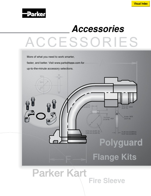
More of what you need to work smarter,AccessoriesV i s u a l I n d e x59RG D-17T1RG D-17Partek Sleeve D-18ParKoil™ (PG) D-19GuardsO-Rings for CA, CE,CF MetricFlange “D” Rings Caterpillar ® Style FlangesT ube O-Ring Fittings and CompressorFittingsO-Rings for Compression Fittings (IT126)O-Rings for C9, OC, 1C Metric Swivels88HC-H Clamp D-2488DB Clamp D-24Hose Assembly D-26Workstations3/4 Reel Rack D-2772B-Cabinet D-28HR6 Hose Bin D-28Hose Adapters D437° Flare Metric Triple-Lok ®Sizes: 6 mm – 38 mmMaterials : Steel, Stainless Steel Pressures : Up to 7200 psi60° Cone BSPPK4Sizes : 1/8” – 2”Materials : Steel Pressures : Up to 5000 psi30° Flare Komatsu StyleSizes : M14 x 1.5 – M33 x 1.5Materials : Steel Pressures : Up to 4000 psiO-Ring Face-Seal Metric Seal-Lok™Sizes: 1/4” – 2”Materials: Steel, Stainless Steel Pressures: Up to 9200 psiJapanese Industrial Standard JISSizes : 1/4” – 1”Materials : Steel Pressures : Up to 5000 psiWhen ordering Parker Adapters, please state the Catalogued Number of each type of adapter desired. Be sure to double check tube and hose sizes of items required.To select proper seal materials for specific applications, refer to Media Compatibility Chart in Tube Fitting Catalog 4300, or contact your Parker Tube Fitting Distributor.If in doubt about which type or size of fitting to specify, consult your Parker Tube Fitting Distributor. In addition Parker Field Sales, Technical Services,the Tube Fitting Division and your local Parker Service Center will help you find answers to all your issues.Phone: (614) 279-7070Fax: (614) 279-7685Web: /tfdNote: Refer to Parker Catalog 4300 for more detailed application information.CALL TOLL-FREE 1-800-C PARKER (1-800-272-7537)Parker Information Center for catalogs, literature or additional information.O-Ring Face-Seal Seal-Lok™ Sizes: 6 mm – 38 mm Materials: Steel, Stainless Steel Pressures: Up to 9200 psi37° Flare FittingsTriple-Lok ®Sizes: 1/8” – 2”Materials: Steel, Stainless Steel, BrassPressures: Up to 9000 psiPipe Fittings and Port AdaptersSizes: 1/8” – 2”Materials : Steel, Stainless Steel, BrassPressures : Up to 7200 psiPipe SwivelsSizes : 1/8” – 2”Materials : Steel, Stainless Steel Pressures : Up to 5000 psiConversion AdaptersSizes: 1/4” – 1-1/2”Materials : Steel, Stainless Steel Pressures : Up to 7700 psiHydraulic Flange and Flange AdaptersSizes : 3/4” – 3”Materials : Steel, Stainless Steel Pressures : Up to 6000 psi15T3SAE (Code 61) Flange – Male SAE (JIC) 37˚ FlareCaution: Do not use the T3 flange to tube or swivel nut to tube adapter in hose assembly applications inwhich pressures exceed the SAE100R2 working pressure range.17T3SAE (Code 61) Flange – Male SAE (JIC) 37˚ Flare - 45˚ Elbow19T3SAE (Code 61) Flange – Male SAE (JIC) 37˚ Flare - 90˚ Elbow39T3Male - Female Swivel - SAE (JIC) 37˚ - 90˚ Elbow41T3Male - Female Swivel - SAE (JIC) 37˚ - 90˚ Elbow - Long4AH3SAE Code 61 Flange - Male SAE (JIC) 37˚ Flare - 5000 psi Caution: Do not use the T3 flange to tube or swivel nut to tube adapter in hose assembly applications in which pressures exceed the SAE100R2 working pressure range.4FH3SAE Code 61 Flange - Male SAE (JIC) 37˚ Flare - 5000 psi -45˚ Elbow4NH3SAE Code 61 Flange - Male SAE (JIC) 37˚ Flare - 5000 psi -90˚ Elbow6AH3SAE Code 62 Flange - Male SAE (JIC) 37˚ Flare6FH3SAE Code 62 Flange - Male SAE (JIC) 37˚ Flare - 45˚ Elbow4AJMCode 61 Flange - Male Seal-Lok4FJMCode 61 Flange - Male Seal-Lok - 45˚ Elbow4NJMCode 61 Flange - Male Seal-Lok - 90˚ Elbow6NH3SAE Code 62 Flange - Male SAE (JIC) 37˚ Flare - 90˚ Elbow6NJMCode 62 Flange - Male Seal-Lok - 90˚ Elbow6FJMCode 62 Flange - Male Seal-Lok - 45˚ Elbow6AJMCode 62 Flange - Male Seal-LokNote:*5000 psi with 4A, 4F and 4N Fittings and 50H Flange Halves.There are two non-interchangeable SAE split flanges: a: S tandard or Code 61 is for 3,000psi to 5,000psi maximum, depending on size.b.H igh Pressure or Code 62 is for 6,000psi maximum, r egardless of size. The flange head is “V” notched for identification.Consult these tables to determine flange halves and flange kits specifications.High Pressure (Code 62)Standard Pressure (Code 61)Note: For use with 4A, 4F and 4N Flanges.50H5000 psi Flange Half (Code 61)Note: For use with 4A, 4F and 4N Flanges.Note: High pressure applications also require the use of Code 61 Flange End hose fittings.51HSAE Flange Half (Code 61)5050HK5000 psi Flange Kit (Code 61)5151HKSAE Flange Kit (Code 61)HFHSAE Flange Half (Code 62) HFHFHKSAE Flange Kit (Code 62) 8FHFlange Half (8000 psi)8FHFHKFlange Kit (8000 psi)DIN and ISO Metric PortsDIN (German) and ISO (International Organization for Standardization) flange heads are the same as SAE flange heads. By comparison, the ports have the same configura-tion except that the DIN and ISO Type I ports accept metric bolts. This requires specialflange halves in most sizes.Note: High pressure applications also require the use of Code 62 Flange End hose fittings.M1HDIN (ISO) Flange HalfM1M1HKDIN (ISO) Flange Kit (Code 61)M2M2HKDIN (ISO) Flange Kit (Code 62)M2HDIN (ISO) Flange Half (Code 62)711509O-Rings - SAE Thread (Compound N552-90)*711510O-Rings - Code 61 and Code 62 Flanges (Compound N552-90)**Note: F or use with petroleum base fluids, other compounds available for Phosphate Ester fluids.Please contact The Parker Hannifin Seal Group/O-Ring Division (1-800-C-PARKER) for additional information.C9RG O-Rings for CA, CE, CF MetricC9RG O-Rings for C9, OC, 1C Metric SwivelsD9DTBonded Seal for BSPP Port Fittings*Note: D 9DT must be ordered from the Tube FittingsDivision. Please contact TFD for additional size and product information.XARGFlange “D” Rings Caterpillar ®Style FlangesJ0RGO-Rings - Seal-Lok ®Note: O -Rings for use in Seal-Lok ® connections are illustrated in actual size. Part numbers for O-Ringsused in Seal-Lok ® and in SAE port connections are also listed in the table. O-Rings are supplied in Nitrile NBR compound, 90 durometer hardness.SAE 711509-4-8Seal-Lok J0RG-8-8Photo shows an actual comparison between an SAE port O-Ring (top) and a Seal-Lok ® O-Ring (bottom). They differ in both diameter and cross section.8ARGFlange “D” Rings for 76 Series Style FlangeT1RGO-Rings for Compression Fittings (1T126)Charge Ports CapsR134aR12CORGCaptive O-Ring Assembly ToolsParker’s new CORG Assembly Tools are designed to facilitate the installation of the O-Ring into the half-dovetail groove of the O-Ring face seal fitting.Note: C ORG Assembly T ools must be ordered from the T ube Fittings Division (614) 279-7070.Note: O -Rings listed are for use with petroleum base fluids. Other compounds are available for Phosphate Ester fluids by special order. For Viton ® or otherO-Ring compounds, consult Parker Hannifin, Seal/O-Rings Products Division (1-800-C-PARKER.)Bench TypeHand Type59RGO-Rings for Tube O-Ring Fittingsand Compressor FittingsNote:T he above O-Rings (RG) have HNBR compound number N1195-70 (green).Accessory Selection Guide – Partek Sleeve (AS-B, AS-Y or PS)Note: T he inside flat “A” dimension correspondswith the inside diameter “B” dimension. For example, AS-Y -13 flat surface “A” is 1.34 in. This offers a .86 in. inside diam-eter “B”. Hose with a smaller O.D. can be specified for this size sleeve. Parker 201-5 hose has a .58 in. O.D. and can easily be inserted in the Partek AS-Y -13Sleeve.Note: 1. T he dimensions shown are related to the hose outside diameter and may not fit over the fitting. For over the fitting applications, a larger sizesleeve may be required.2. Cut lengths are available. Contact your local distributor for prices ().Partek SleevePartek “PS” SleeveParker’s Partek Nylon Protective Sleeving gives you tough hose abrasion protection two ways. First, per the ISO 6945 specification, Partek has a unique tubular weave nylon construction, Partek “AS” is strong enough to withstand greater than 200,000 abrasion cycles without wearing through the fabric at any loca-tion. Partek “PS” can withstand greater than 50,000 abrasion cycles. In addition, this weave also gives an exceptionally smooth interior wall, allowing rubber hose to move freely inside the sleeve. This provides easy installation and prevents any internal abrasion problems. Partek sleeving is available in either black or yellow and in sizes to fit most hydraulic hose. Partek, the quick and easy solution to hose protection in high-abrasion areas.Temperature Range: -67°F to +248°F (-53°C to +120°C)Accessory Selection Guide – PolyGuard (HG)• S hield hose from abrasion and cuts • Minimize kinking• Cannot rust or corrode • R esist water, oil, gasoline, hydraulic fluid, and most solvents • I deal for bundling plastic tubing or hose lines • E asy to install without removing hose lines; no clamps neededPolyGuardHeavy-duty polyethylene provides protection in rugged operating conditions.Great for b undling high-pressure hose lines.Cut edges can be smoothed by applying heat.CAUTION: This material will support combustion.Color: BlackTemperature Range:0˚F to +200˚F (-17˚C to +93˚C)Parkoil ™Lower-cost protection for applications that call for a tighter bend radius and are less demanding.Cut edges can be smoothed by applying heat.CAUTION: This material will support combustion.Color: BlackTemperature Range:0˚F to +200˚F (-17˚C to +93˚C)Accessory Selection Guide – ParKoil ™ (PG)Accessory Selection Guide – Spring Guard and Armor GuardNote:Spring Guard and Armor Guard are packaged in 10 ft. pieces.Parker Spring Guard and Armor Guard are two products that prolong the life of hose lines that are exposed to rugged operating conditions. They distribute bending radii to avoid kinking in hose lines and protect hose from abrasion and deep cuts. Guards areconstructed of steel wire and plated to resist rust.Spring Guard (SG)Armor Guard (AG)Accessory Selection Guide – Firesleeve (FS-F)Parker Firesleeve is a flame resistant sheath that protects the hose from extreme temperature conditions. Firesleeve easily slides over hoses and readily expands over fitting. It can be assembled with Parker FSC or properly sized wormgear clamp.Construction: Braided fiberglass sleeve and an orange,bonded and seamless silicone rubber cover.Specifications: Conforms to SAE Aerospace Standard 1072A Type 2A.Temperature Range:-54˚C to +260˚C (-65˚F to +500˚F).Note: T he Firesleeve inside dimension (I.D.)must exceed the outside diameter (O.D.) of the hose and offer an allowance for easy hose insertion. For example, 201-16 has a 1.23 in. O.D. FS-S-24, with an I.D. of 1.46 in., is the suggested Firesleeve. Note: P arker FSC Clamp fits all hoses up to2 in. O.D. Note: P arker HC Clamps (wormgear) are listedon page D-24.Note: See Page D-22 for Firesleeve assembly instructions.Firesleeve (FS-F)FSC ClampPart Number: FSC(One size fits all hoses up to 2 inch O.D.)Accessory Selection Guide – Firesleeve (cont.)1. A ssemble one end fitting on hose. Cut firesleeve to same length as hose. Cover approximately 1” of each end of fire-sleeve with FSS sealant and allow to dry.2. P ush firesleeve back from cut end of hose and assemble the second end fitting. Then pull firesleeve completely over both sockets.3. I nsert tail of FSC clamp into FST clamping tool.4. P osition clamp around middle of socket and tighten with tool. Bend end of band back over buckle. Repeat on other end.Repair any scuffs or abrasions in firesleeve with FSS sealant.FSC ClampUsed to attach firesleeve around socket on hose sizes with a 2” maximum O.D.FST Clamp ToolPart Number: FST -711617 Used to secure FSC clamp.FSS Firesleeve SealantKeeps end of firesleeve from fraying - for neater, longer lasting installation.FiresleeveAssembly InstructionsAccessory Selection Guide – CL ClampVinyl coated steel clamps provide hose support where long lengths are used. Provides neater installation of hose lines, minimizes hose chafing and prevents damage to hose.Material: CR Steel with Zinc PlatingCoating: Black Vinyl Plastisol - 0,8 mm (0.03 inch) thick.Temperature Range:-40°C to +107°C (-40°F to +225°F).Accessory Selection Guide – HC, 88HC-H and 88DB ClampThe Parker HC Clamp is a stainless steel worm gear clamp designed for low presure industrial hose applications.Material: Stainless steelSpecifications: SAE J1508, Type F and Type HD88HC-HSeries Hose Clamp(High Torque Wormgear)88DBSeries Heavy Duty Hose Clamp(Double Bolt Hose Clamp)HC Hose Clamp TableNote: See 88 Series Assembly Instructions for proper 88HC-H clamp attachment.Accessory Selection Guide – Protection Shields (HP , HT, and HP-B)Prevent hose abrasion while extending your hose life. Parker Hose Protection Shields extend hose life by protecting the hose from abrasion that occurs when hose rubs against other hose, metal or concrete. Parker hose shields are resistant to oil, lubricants, gasoline, most solvents and can withstand ambient temperatures from -40° to +300° F . Easily installed and secured by cable ties without disconnect-ing any hose lines. Use with hose from 1/4” to 2” I.D.♦ Eliminate hose abrasion on concrete, metal or any rough surface. ♦ Guard against hose deterioration on mobile hydraulic equipment. ♦Let Parker fill all your hydraulic and pneumatic hose product needs.Hose Protector Shields are a fast and extremely cost effective way to isolate fluid lines from direct contact with other lines, components or structural members. They’re available in 4-inch, 6-inch and 8-inch lengths and the width can be trimmed to satisfy a variety of situations. These flexible protectors simply clamp around the hose and are securely held in place by nylon cable ties which are included. The cable ties are recessed in molded grooves to protect them from abrasion. You don’t need to disconnect a line to install a Parker Hose Protector Shield the way you do with a continuous tubular sleeve. Just wait until the installation is up and running to see exactly where contact needs to be prevented.Parker Hose Protector Shields are available in bulk quantities and in convenient assortments in 4”, 6” and 8” sizes. Cable ties are included with all protectors and are also available in bulk.Hose ShieldsTie Wraps HP-B-13X18-KIT2 ea. HP-13 RFL HT -12-KIT 30 ea. HT -12 Tie Wraps 2 ea. HP-15 RFL HT -16-KIT 30 ea. HT -16 Tie Wraps4 ea. HP-18 RFLHT -22-KIT15 ea. HT -22 Tie Wraps20 Hose Protectors and 60 Tie Wraps for each size are in point of purchase display box.HP-B-13-RFL 10 ea. HP-B-13 Hose Protectors (4”). 30 ea. HT -12 Tie Wraps in a sealed plastic bag.HP-B-15-RFL10 ea. HP-B-15 Hose Protectors (6”). 30 ea. HT -16 Tie Wraps in a sealed plastic bag.HP-B-18-RFL5 ea. HP-B-18 Hose Protectors (8”). 15 ea. HT -22 Tie Wraps in a sealed plastic bag.Contact your authorized Parker Hose Products Distributor for pricing and delivery information.Note: Parker Hose Protector Shield products are intended to prevent damage. They are not suitable as patches or repairs for lines which are already damaged or worn beyond safe use standards.Counter DisplayThe complete on-site complete hose assembly workstation design (above) includes:• TH7-5-C—6’ table with 1 hose reel and 1 bottom shelf • TH7-6—16 hose reel system, with rotating base • T H7-7—15” wide table set up for Parker 239 or 339 Cut-Off Saw Specifications: HoseFab Table (heavy duty)• Laminated wood table top • 1-1/2” square tubing structure • Gussetted corner braces • 6-leg design• All legs have adjustable feet • Hose reel/shelf combinations• 40B-Cabinet or 72B-Cabinet for fitting storage • Optional: Hose trough for measurement of hose • Calibrated to line up to Saw Table • Adjustable stop for standard length cuts• Built-in tape measureSpecifications: Rotary Reel Rack (TH7-6)• 16 Hose reel capacity • Compact design• Rotates for 1 man use• Center post bolts to floor in 4 places • Optional: Overhead craneSpecifications: Saw Table (TH7-7)• Calibrated to line up to Hose trough • Adjustable feet• Mounts to 6-foot benchSpecifications: 3 or 4 Reel Rack • Free standing 3 reel rack (TH7-8)• Bolts to floor• Optional: 4th reel capacity with wall mounts (TH7-8-F)• (2) 40B-Cabinet 40 openings - 4·1/2” x 4·1/2” x 12” in size • TH7-6-C—Optional overhead crane • T H7-5-HT—Optional 6’ measured hose trough with ad -justable hose stopPictured left is a complete on-site hose assembly workstation, the Parker Kart:The Parker Kart, TH7-4, is a portable all-in-one unit designed to hold a Minikrimp, Karrykrimp, Karrykrimp 2, or Parkrimp 1; a 332T -115V Cut-off Saw; 4 reels of hose; and has a 40 bin cabinet with 3 drawers for tools. The TH7-4 can be customized to fit your specific hose assembly needs. Contact Parker HPD or your Parker Hose distributor for details.Note: Part number TH7-4 does not include hose, fittings or equipment.Note: Part number and specifications of components for both workstations are listed on the following pages.HPD Hose Assembly WorkstationsHose Products Division has set up an agreement to allow Hose Products customers to purchase directly from our vendor, Safety Step.Safety Step’s contact information is:Safety Step Annette Cox 888-448-4237*********************See Safety Step contact information at the top of this pageSaw TableFeaturesThe Saw Table, specially designed for Parker 239 or 339 Hose Cut-Off Saw, attaches directly to the HoseFab Table.Part Number DescriptionTH7-715” wide table set up for Parker 239 or 339 Cut-Off Saw Table measurements:H eight - 18” Width - 28”Length - 14”3/4 Reel RackFeaturesCompact in its design, the standard version will hold 3 reels of hose. Optional 4th reel capacity designed with wall anchor mounts.P art Number DescriptionTH7-8 Upright 3 hose reel rackTH7-8-FO ptional extension with wall anchor for 4th reel Rack measurements:Height - 59” (82·1/2” with 4th reel option) Width - 27·3/4”Length - 27·1/2”HoseFab TableFeaturesHeavy duty constructed table for mounting Minikrimp, Karrykrimp, Karrykrimp 2, or Parkrimp 1. HoseFab Table is available in 3 versions to meet your require-ments. Options include two 40B-Cabinets or 72B-Cabinets for fitting storage.Part Number Description TH7-5-R 6’ table with 2 hose reels TH7-5-S 6’ table with 2 bottom shelves TH7-5-C 6’ table with 1 hose reel and 1 bottom shelf TH7-5-HT O ptional 6’ measured hose trough with adjustable hose stop 40B-Cabinet 40 openings - 4·1/2” x 4·1/2” x 12” in size 72B-Cabinet 72 openings - 4·1/2” x 4·1/2” x 12” in size Table measurements: Height - 31-3/4” Width - 29”Length - 72”Rotary Reel RackFeatures16 Hose reel capacity that fits in a compact area. Supplied with heavy duty casters which allow for ease of turning, even when fully loaded. Optional overhead crane available.Part Number DescriptionTH7-6 16 hose reel system, with rotating base TH7-6-C Optional overhead craneRack measurements:Height - 104” (120” with optional overhead crane) Width - 67”Length - 67”See Safety Step contact information on page D-26See Safety Step contact information on page D-26See Safety Step contact information on page D-26See Safety Step contact information on page D-26Parker Kart Part No. TH7-4Parker Kart organizes and stores all your necessary Parker hoses, fittings, power and hand tools - everything you need to make fast hose assemblies on site. As a valued addition to any facility, Parker Kart will save on downtime and labor costs, as well as eliminate errors in cutting and fitting attachment. With Parker Kart, you’ll always have the materials you need, right when and where you need them.• Easy one-man movement• Eight-inch urethane casters with brakes• Forklift carry tubes• Electric receptable with cord• Fitting bins and drawers• Large tool drawer• Four hose reel holders• Choice of Parker crimping equipment• Optional accessories availableParker Kart can be customized to fit specific hose assem-bly needs. Parker Kart does not include hose, fittings orequipment.Fitting Stock Bins72B-Cabinet36” wide, 43” high, 12” deep, with 72 openings each 4-1/2”x 4-1/2” x 12”, heavy duty steel, all welded construction.Product bin labels are available.Hose Stock BinsHR6-Hose-BinRugged metal cabinet for stocking coils of Parker hose 36”wide, 28” high, 20” deep, with upright separators to provide6 compartments varying in width from 4” to 8”.Provides suitable base on which to place the fittings stockbin (top measures 36” x 20”, bottom of fittings bin measures36” x 12”.)Yellow with black “Parker Hose” lettering.See Safety Step contact information on page D-26。
263系列金属螺杆尖耐抗电尖耐抗电尖通螺杆类型环形编码器说明书
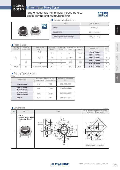
Through shaft type
Horizontal
Horizontal
—
12/12
12/24 12/12
9/18 15/30
Ring type
— 15/30
Features
W
Dimensions (mm)
D
H
Operating temperature range
Operating life Automotive use Life cycle (availability)
300V AC for 1minute or 360V AC for 2s
300V AC for 1minute or 360V AC for 1s
—
7±5mN・m 12±5mN・m 16±7mN・m
—
17±8mN・m(Initial) 12+− 74mN・m(After reflow)
100N
Shaft configuration
1
Style
5-3.5 9
4 Mounting surface
3 2
120°
ø21.6
C ø12.2
AB 1
2-8
120°
0.7
2-10.4 120°
Unit:mm
PC board mounting hole dimensions (Viewed from mounting side)
22.3
3
˃˃
˃ $ ˃ $
˃˃
"# "#
EC21A Actuator length 15mm 9 pulse/18 detent
P11C68-35CGDPBS资料

1DS3600-1.2 September 1992PRELIMINARY INFORMATIONP10C68/P11C68(Previously PNC10C68 and PNC11C68)CMOS/SNOS NVSRAMHIGH PERFORMANCE 8 K x 8 NON-VOLATILE STATIC RAM(Supersedes DS3159-1.3, DS3160-1.3, DS3234-1.1, DS3235-1.1)The P10C68 and P11C68 are fast static RAMs (35 and 45ns) with a non-volatile electically-erasable PROM (EEPROM)cell incorporating in each static memory cell. The SRAM can be read and written an unlimited number of times while independent non-volatile data resides in PROM.On the P10C68 data may easily be transferred from the SRAM to the EEPROM (STORE) and from the EEPROM back to the SRAM ( RECALL) using the NE (bar) pin. The Store and Recall cycles are initiated through software sequences on the P11C68. These devices combine the high performance and ease of use of a fast SRAM with the data integrity of non-volatility.The P10C68 and P11C68 feature the industry standard pinout for non-volatile RAMs in a 28-pin 0.3-inch plastic and ceramic dual-in-line packages.FEATURESI Non-Volatile Data IntegrityI 10 year Data Retention in EEPROMI 35ns and 45ns Address and Chip Enable Access Times I 20ns and 25ns Output Enable Access I Unlimited Read and Write to SRAM I Unlimited Recall Cycles from EEPROM I 104 Store Cycles to EEPROM I Automatic Recall on Power up I Automatic Store Timing I Hardware Store Protection I Single 5V ± 10% OperationI Available in Standard Package 28-pin 0.3-inch DIL plastic and ceramic I Commercial and Industrial temperature ranges Pin Name FunctionA 0 - A 12Address inputs WWrite enable DQ 0 - DQ 7Data in/out E Chip enable G Output enable V CC Power (+5V)V SSGroundPin 1NE Non volatile enable P10C68Pin 1N/C No connection P11C6812345678910111213142827262524232221201918171615V W NC A A A G A E DQ DQ DQ DQ DQ 76543891110CC NE A A A A A A A A A DQ DQ DQ V 1276543210012ssFigure 1. Pin connections - top view.ORDERING INFORMATION (See back page)F igure 2. Logic block diagram. 23Value ParameterSupply voltageInput logic '1' voltage Input logic '0' voltageAmbient operating temperaturecommercial industrialSymbolV CC V IH V IL T amb T ambMin.2.2V SS -0.50-40ConditionsAll inputs All inputsMax.V CC +0.50.8+70+85Typ.5.0DC OPERATING CONDITIONSDC ELECTRICAL CHARACTERISTICS Commercial temperature rangeTest conditions (unless otherwise stated):Tamb = 0°C to 70°C, Vcc = +5V (See notes 1, 2 and 3)CharacteristicAverage power supply currentAverage power supply current during STORE cycleAverage power supply current (standby, cycling TTL input levels)Average power supply current(standby, stable CMOS input levels)Input leakage current (any input)Off state output leakage current Output logic '1' voltage Output voltage '0' voltageSymbolI CC1I CC2I SB1I SB2I ILK I OLK V OH V OLValueUnitsmA mA mAmA mAmAµA µA V VConditionst AVAV = 35ns t AVAV = 45nsAll inputs at V IN ≤ 0.2V t AVAV = 35ns t AVAV = 45nsE(bar) ≥V IH , all other inputs cyclingE (bar)≥(V CC -0.2V), all other inputs at V IN ≤0.2V or ≥(V CC -0.2V)V CC = max, V IN = V SS to V CC V CC = max, V IN = V SS to V CC I OUT = 4mA I OUT = 8mAMax.75655023201±1±50.4Min.2.4NOTES 1.I CC1 is dependent on output loading and cycle rate. The specified values are obtained with outputs unloaded.2.Bringing E (bar) ≥ V IH will not produce standby currents levels until any non-volatile cycle in progress has timed out. SeeMode Selection table.3.I CC2 is the average current required for the duration of the STORE cycle (t STORE ) after the sequence that initiates thecycle.ABSOLUTE MAXIMUM RATINGSVoltage on typical input relative to VSS-0.6V to 7.0V Voltage on DQ0-7 and G(bar)-0.5V to (Vcc + 0.5V)Temperature under Bias -55°C to + 125°C Storage temperature -65°C to + 150°C Power dissipation 1W DC output current15mA(one output at a time, one second duration)NOTEStresses greater than those listed in the Absolute Maximum Ratings may cause permanent damage to the device. These are stress ratings only; functional operation of the device at any other conditions than those indicated in the operational sections of the specification is not implied.Exposure to absolute maximum ratings conditions for extended periods may affect reliability.Units V V VoC oC4CharacteristicAverage power supply currentAverage power supply current during STORE cycleAverage power supply current (standby, cycling TTL input levels)Average power supply current(standby, stable CMOS input levels)Input leakage current (any input)Off state output leakage current Output logic '1' voltage Output voltage '0' voltageIndustrial temperature rangeTest conditions (unless otherwise stated):Tamb = -40˚C to 70˚C, Vcc = +5V ± 10% (See notes 4, 5 and 6)SymbolI CC1I CC2I SB1I SB2I ILK I OLK V OH V OLValueUnitsmA mA mAmA mAmAµA µA V VConditionst AVAV = 35ns t AVAV = 45nsAll inputs at V IN ≤ 0.2V t AVAV = 35ns t AVAV = 45nsE(bar) ≥V IH , all other inputs cyclingE (bar)≥(V CC -0.2V), all other inputs at V IN ≤0.2V or ≥(V CC -0.2V)V CC = max, V IN = V SS to V CC V CC = max, V IN = V SS to V CC I OUT = 4mA I OUT = 8mAMax.80755027231±1±50.4Min.2.4Input pulse levelsInput rise and fall timesInput and output timing reference levels Output loadV SS to 3V ≤5ns 1.5VSee Figure 3AC TEST CONDITIONSCAPACITANCE T amb = 25°C, f = 1.0MHz (see note 7)Parameter Input capacitance Output capacitanceSymbol C IN COUTUnits pF pFMax.57Conditions ∆V=0 to 3V ∆V=0 to 3VNOTE7. These parameters are characterised but not 100% tested.NOTES 4.I CC1 is dependent on output loading and cycle rate. The specified values are obtained with outputs unloaded.5.Bringing E (bar) ≥ V IH will not produce standby currents levels until any non-volatile cycle in progress has timed out. SeeMode Selection table.6.I CC2 is the average current required for the duration of the STORE cycle (t STORE ) after the sequence that initiates thecycle.Figure 3. AC output loading.5SRAM MEMORY OPERATIONTest conditions (unless otherwise stated):Commercial and Industrial Temperature RangeTamb = -40°C to + 85°C, Vcc = + 5V ± 10%READ CYCLES 1 AND 2 (See note 8)NOTES 8. E (bar), G (bar) and W (bar) must make the transition between VIH(min) to VIL(max), or VIL(max) to VIH(min) in amonotonic fashion. NE (bar) must be ≥ VIH during entire cycle.9.For READ CYCLE 1 and 2, W (bar) and NE (bar) must be high for entire cycle.10.Device is continuously selected with E (bar) low, and G (bar) low.11.Measured ±200mV from steady state output voltage. Load capacitance is 5pF.12.Parameter guaranteed but not tested.Figure 4. READ CYCLE 1 timing diagram (see notes 9 and 10).Standard t ELQV t AVAV t AVQV t GLQV t AXQX t ELQX t EHQZ t GLQX t GHQZt ELICCHt EHICCL t WHQVAlternativet ACS t RC t AA t OE t OH t LZ t OHZ t OLZ t HZ t PA t PS t WRParameter Chip enable access time Read cycle timeAddress access timeOutput enable to data validOutput hold after address change Chip enable to output active Chip disable to output inactive Output enable to output active Outout disable to output inactive Chip enable to power active Chip disable to power standby Write recovery timeUnits ns ns ns ns ns ns ns ns ns ns ns nsNotes91011111212P10C68-45P11C68-45P10C68-35P11C68-35SymbolMin.4555Max.45452525202555Min.3555Max.353520201525456WRITE CYCLE 1 : W (BAR) CONTROLLED (See notes 8 and 13)Commercial and Industrial Temperature RangeF igure 5. READ CYCLE 2 timing diagram (see note 9).Standard t AVAV t WLWH t ELWH t DVWH t WHDX t AVWH t AVWL t WHAX t WLQZ t WHQZAlternativet WC t WP t CW t DW t DH t AW t AS t WR t WZ t OWParameterWrite cycle time Write pulse widthChip enable to end of write Data set-up to end of write Data hold after end of write Address set-up to end of write Address set-up to start of write Address hold after end of write Write enable to output disable Output active after end of writeUnitsns ns ns ns ns ns ns ns ns nsNotes11, 14P10C68-45P11C68-45P10C68-35P11C68-35SymbolMin.45353530035005Max.35Min.45353530035005Max.35NOTES 13. E (bar) or W (bar) must be ≥ VIH during address transitions.14.If W (bar) is low when E (bar) goes low, the outputs remain in the high impedance state.7F igure 6. WRITE CYCLE 1: W (bar) controlled timing diagram (see notes 8 and 13).Standard t AVAV t WLEH t ELEH t DVEH t EHDX t AVEH t EHAX t AVWLAlternativet WC t WP t CW t DW t DH t AW t WR t ASParameterWrite cycle time Write pulse widthChip enable to end of write Data set-up to end of write Data hold after end of write Address set-up to end of write Address hold after end of write Address set-up to start of writeUnitsns ns ns ns ns ns ns nsNotesP10C68-45P11C68-45P10C68-35P11C68-35SymbolMin.4535353003500Max.Min.4535353003500Max.WRITE CYCLE 2 : E (BAR) CONTROLLED (See notes 8 and 13)F igure 7. WRITE CYCLE 2: E (bar) controlled timing diagram (see notes 8 and 13).8Figure 8. Automatic RECALL and STORE inhibit.NON-VOLATILE MEMORY OPERATION OF P10C68MODE SELECTIONW X H L H L L HE H L L L L L LG X L X L H L HNE X H H L L L XPower Standby Active Active Active I CC2ActiveModeNot selected Read RAM Write RAMNon-volatile recall (Note 15)Non-volatile store No operationNOTE 15.An automatic RECALL also takes place on chip power-up, starting when Vcc exceeds 3.3V, and taking t RECALL from thetime at which Vcc exceeds 3.3V. Vcc must not drop below 3.3V once it has exceeded it for the RECALL to function properly.Standard t WLQX t GHNL t NLWL t WLNH t ELWLAlternative t STORE t WCParameterStore cycle timeOutput disable set-up to NE (bar) fall Non-volatile set-up to write low Write low to NE (bar) rise Chip enable SET-UPSymbolNotes1718Unitsms ns ns ns nsMin.00450Max.10Min.00450Max.10STORE CYCLE 1 : W (BAR) CONTROLLED (See note 16)P10C68-35P10C68-459STORE CYCLE 2 : E (BAR) CONTROLLED (See note 13)Standard t ELQX1t NLEL t WLEL t ELNH t GHELAlternative t STORE t WCParameterStore cycle timeNE (bar) set-up to chip enableWrite enable wet-up to chip enable Chip enable to NE (bar) riseOutput disable set-up to E (bar) fallSymbolNotes1718Unitsms ns ns ns nsMin.00450Max.10Min.00450P10C68-35P10C68-45Max.10NOTES16. E (bar), G (bar), NE (bar) and W (bar) must make the transition between VIH(max) to VIL(max), or VIL(max) to VIH(min) in a monotonic fashion.17. Measured with W (bar) and NE (bar) both returned high, and G (bar) returned low. Note that store cycles are inhibited/aborted by Vcc <3.3V (STORE inhibit).18. Once twc has been satisfied by NE (bar), G (bar), W (bar) and E (bar) the store cycle is completed automatically, ignoring allinputs. Any of NE (bar), G (bar), W (bar) or E (bar) may be used to terminate the store initiation cycle.Figure 9. STORE CYCLE 1: W (bar) controlled timing diagram (see note 16).Figure 10. STORE CYCLE 2: E (bar) controlled timing diagram (see note 16).10Standard t NLQX t NLNH t GLNL t WHNL t ELNL t NLQZAlternative t RECALL t RCParameterRecall cycle timeRecall initiation cycle time Output enable set-up Write enable set-up Chip enable set-upNE (bar) fall to output inactiveUnitsµs µs ns ns ns nsNotes1920SymbolMin.25000Max.2025Min.25000Max.2025P10C68-45P10C68-35P10C68 RECALL CYCLE 1 : NE (BAR) CONTROLLED (See note 16)P10C68 RECALL CYCLE 3 : G (BAR) CONTROLLED (See note 16)Alternative t RECALL t RCParameterRecall cycle timeRecall initiation cycle time NE (bar) set-up Write enable set-up Chip enable set-upUnitsµs ns ns ns nsNotes1920SymbolMin.25000Max.20Min.25000Max.20P10C68-45P10C68-35Standard t GLQX2t GLNH t NLGL t WHGL t ELGLNOTES 19.Measured with W (bar) and NE (bar) both returned high, and G (bar) returned low. Address transitions may not occur onany address pin during this time.20.Once t RC has been satisfied by NE (bar), G (bar), W (bar) and E (bar) the RECALL cycle is completed automatically. Anyof NE (bar), G (bar) or E (bar) may be used to terminate the RECALL initiation cycle.P10C68 RECALL CYCLE 2 : E (BAR) CONTROLLED (See note 16)Alternative t RECALL t RCParameterRecall cycle timeRecall initiation cycle time NE (bar) set-upOutput enable set-up Write enable set-upUnitsµs ns ns ns nsNotes1920SymbolMin.25000Max.20Min.25000Max.20P10C68-45P10C68-35Standard t ELQX2t ELNH t NLEL t GLEL t WHELP10C68/P11C6811Figure 11. P10C68 RECALL CYCLE 1: NE (bar) controlled timing diagram (see note 16).Figure 12. P10C68 RECALL CYCLE 2: E (bar) controlled timing diagram (see note 16).Figure 13. P10C68 RECALL CYCLE 3: E (bar) controlled timing diagram (see note 16).P10C68/P11C6812Notes2221, 2221, 2221, 2221, 2221, 222021, 2221, 2221, 2221, 2221, 2221Power Standby Active Active ActiveI CC2Active I/O Output High Z Output data Input Data Output Data Output Data Output Data Output Data Output Data Output High Z Output Data Output Data Output Data Output Data Output Data Output High ZModeNot selected Read RAM Write RAM Read RAM Read RAM Read RAM Read RAM Read RAMNon-volatile STORE Read RAM Read RAM Read RAM Read RAM Read RAMNon-volatile RECALLA 12-A 0 (hex)X X X 000015550AAA 1FFF 10F00F0F000015550AAA 1FFF 10F00F0EE H L L LLW X H L HHStandard t AVAVt AXAV t AVQZ t AVEL t ELEH t EHAXAlternativet ACSt SKEW t ELQZt STORE t RECALL t AE t EP t EA ParameterRead cycle timeSkew between sequentially adjacent addressesAddress valid to output inactive Store cycle time Recall cycle timeAddress set-up to chip enable Chip enable pulse widthChip disable to address changeUnitsns ns ns ms µs ns ns nsNotes23252626, 30272727SymbolMin.450450Max.5751020Min.350350Max.5751020P11C68-45P11C68-35NOTES 23.Skew spec may be avoided by using E (bar) (STORE/RECALL CYCLE 2).24.W (bar) ≥V IH during entire address sequence to initiate a non-volatile cycle.Required address sequences are shown in the Mode Selection table.25.Once the software STORE or RECALL cycle is initiated, it completes automatically, ignoring all inputs.26.Measured with W (bar) high, G (bar) low and E (bar) low. Note that STORE cycles (but not RECALLS) are aborted by Vcc< 3.3V (STORE Inhibit).27. E (bar) must make the transition between V IH (max) to V IL (max), or V IL (max) to V IH (min) in a monotonic fashion.28.Chip is continuously selected with E (bar) low.29.Addresses 1 through 6 are found in the Mode Selection table. Address 6 determines whether the P11C68 performs aSTORE or RECALL. A RECALL cycle is performed automatically at power up when V CC exceeds 3.3V. V CC must not drop below 3.3V once it has exceeded it for the RECALL to function properly, t RECALL is measured from the point at which V CC exceeds 3.3V.30.Address transitions may not occur on any address pin during this time.NOTES 21.The six consecutive addresses must be in order listed - (0000, 1555, 0AAA, 1FFF, 10F0, 0F0F) for a STORE cycle or(0000, 1555, 0AAA, 1FFF, 10F0, 0F0E) for a RECALL cycle. W (bar) must be high during all six consecutive cycles. See STORE CYCLE and RECALL CYCLE tables and diagrams for further details.22.I/O state assumes that G (bar) ≥V IL . Activation of non-volatile cycles does not depend on the state of G (bar).STORE / RECALL CYCLES 1 AND 2 (See notes 24 and 29)NON-VOLATILE MEMORY OPERATION OF P11C68MODE SELECTIONP10C68/P11C6813OPERATING NOTESNote: References to NE (bar) should be taken as applying to P10C68 only and can be ignored for P11C68.The devices have two separate modes of operation: SRAM mode and non-volatile mode. In SRAM mode, the memory operates as an ordinary static RAM. While in non-volatile mode, data is transferred in parallel from SRAM to EEPROM or from EEPROM to SRAM.SRAM READThe devices perform a read cycle when ever E (bar) and G (bar) are LOW and NE (bar) and W (bar) are H IGH. The address specified by the thirteen address pins A 0-12 determine which of the 8192 data bytes will be accessed. When the READ is initiated by an address transistion, the outputs will be valid after a delay of t AVQV (READ CYCLE 1).If the READ is initiated by E (bar) or G (bar), the outputs will be valid at t ELQV or t GLQV , whichever is later. (READ CYCLE 2).The data outputs will repeatedly respond to address changes within the t AVQV access time without the need for transitions on any control input pins and will remain valid until another address change or until E (bar) or G (bar) is brought HIGH or W (bar) or NE (bar) is brought LOW.SRAM WRITEA write cycle is performed whenever E (bar) and W (bar)are LOW and NE (bar) is HIGH. The address inputs must be stable prior to entering the WRITE cycle and must remain stable until either E (bar) or W (bar) go HIGH at the end of the cycle. The data on the eight pins DQ 0-7, will be written into the memory location specified by the address inputs if valid t DVWH before the end of a W (bar) controlled WRITE or t DVEH before the end of an E (bar) controlled WRITE.Figure 15. STORE/RECALL cycle 2. E (bar) controlled timing diagram (see notes 22, 25 and 27).Figure 14. STORE/RECALL cycle 1. Address controlled timing diagram (see notes 22, 26 and 27).P10C68/P11C6814It is recommended that G (bar) be kept HIGH during theentire WRITE cycle to avoid data bus contention on the common I/O lines. If G (bar) is left LOW, internal circuitry will turn off the output buffers t WHQZ after W (bar) goes LOW.Non-Volatile STORE - P10C68A STORE cycle is performed when NE, (bar) E (bar) and W (bar) are LOW and G (bar) is HIGH. While any sequence to achieve this state will initiate a STORE, only W(bar) initiation (STORE CYCLE 1) and E (bar) initiation (STORE CYCLE 2) are practical without risking an unintentional SRAM WRITE that would disturb SRAM data. During the STORE cycle, previous non-volatile data is erased and the SRAM contents are then programmed into non-volatile elements. Once a STORE cycle is initiated, further input and output is disabled and the DQ0-7 pins are tri-stated until the cycle is completed.If E (bar) and G (bar) are LOW and W (bar) and NE (bar) are HIGH at the end of the cycle, a READ will be performed and the outputs will go active, signalling the end of the STORE.The P10C68 will not be activated into either a STORE or RECALL cycle by the software sequence required for the P11C68.Hardware Protect - P10C68The P10C68 offers two levels of protection to suppress inadvertent STORE cycles. If the clock signals remain in the STORE condition at the end of a STORE cycle, a second STORE cycle will not be started. The STORE will be initiated only after a HIGH to LOW transition on NE (bar)Because the STORE cycle is initiated by an NE (bar) transition, powering-up the chip with NE (bar) Low will not initiate a STORE cycle either.In addition to multi-trigger protection, the P10C68 offers hardware protection through Vcc Sense. A STORE cycle will not be initiated, and one in progress will discontinue, if Vcc goes below 3.3V.Non-Volatile RECALL - P10C68A RECALL cycle is performed when E (bar), G (bar) and NE (bar) are LOW and W (bar) is HIGH. Like the STORE cycle, RECALL is initiated when the last of the four clock signals goes to the RECALL state. Once initiated, the RECALL cycle will take t NLQX to complete, during which all inputs are ignored. When the RECALL completes, any READ or WRITE state on the input pins will take effect.Internally, RECALL is a two step procedure. First the SRAM data is cleared and second, the non-volatile information is transferred into the SRAM cells. The RECALL operation in no way alters the data in the non-volatile cells. The non-volatile data can be recalled an unlimited number of times. Address transitions may not occur during the RECALL cycle. Like the STORE cycle, a transition must occur on the NE (bar) pin to cause a RECALL, preventing inadvertent multi-triggering. On power-up, once Vcc exceeds Vcc sense voltage of 3.3V, a RECALL cycle is automatically initiated. The voltage on the Vcc pin must not drop below 3.3V once it has risen above it in order for the RECALL to operate properly. Due to the automatic RECALL, SRAM operation cannot commence until t NLQX after Vcc exceeds 3.3V.The P11C68 STORE cycle is initiated by executing sequential READ cycles from six specific address locations. By relying on READ cycles only, the P11C68 implements non-volatile operation while remaining pin-for-pin compatible with standard 8Kx8 SRAMs. During the STORE cycle, an erase of the previous non-volatile data is first performed, followed by a program of the non-volatile elements. The program operation copies the SRAM data into non-volatile storage. Once a STORE cycle is initiated, further input and output are disabled until the cycle is completed. Because a sequence of addresses is used for STORE initiation, it is critical that no invalid address states intervene in the sequence or the sequence will be aborted. The maximum skew between address inputs A0-12 for each address state is t SKEW (STORE CYCLE 1).If t SKEW is exceeded it is possible that the transitional data state will be interpreted as a valid address and the sequence will be aborted. If E (bar) controlled READ cycles are used for the sequence (STORE CYCLE 2), address skew is no longer a concern.To enable the STORE cycle the following READ sequence must be performed.1. Read address 0000 (hex) Valid READ2. Read address 1555 (hex) Valid READ3. Read address 0AAA (hex) Valid READ4. Read address 1FFF (hex) Valid READ5. Read address 10F0 (hex) Valid READ6. Read address 0F0F (hex) Initiate STORE CycleOnce the sixth address in the sequence has been entered, the STORE cycle will commence and the chip will be disabled. It is important that READ cycles and not WRITE cycles be used in the sequence, although it is not necessary that G (bar) be LOW for the sequence to be valid. After the t STORE cycle time has been fulfilled, the SRAM will again be activated for READ and WRITE operation.Once the first of the six reads has taken place, the read sequence must either complete or terminate with an incorrect address (other than 0000 hex) before it may be started anew.The P11C68 offers hardware protection against inadvertent STORE cycles through Vcc Sense. A STORE cycle will not be initiated, and one in progress will discontinue, if Vcc goes below 3.3V.A RECALL of the EEPROM data into the SRAM is initiated with a sequence of READ operations in a manner similar to the STORE initiation. To initiate the RECALL cycle the following sequence of READ operations must be performed:1. Read address 0000 (hex) Valid READ2. Read address 1555 (hex) Valid READ3. Read address 0AAA (hex) Valid READ4. Read address 1FFF (hex) Valid READ5. Read address 10F0 (hex) Valid READ6. Read address 0F0E (hex) Initiate RECALL CycleInternally, RECALL is a two step procedure. First, the SRAM data is cleared and second the non-volatile information is transferred into the SRAM cells. The RECALL operation in no way alters the data in the EEPROM cells. The non-volatile data can be recalled an unlimited number of times. Address transitions may not occur during the RECALL cycle.P10C68/P11C6815On power-up, once Vcc exceeds the Vcc sense voltage of 3.3V, a RECALL cycle is automatically initiated. The voltage on the Vcc pin must not drop below 3.3V once it has risen above it in order for the RECALL to operate properly. Due to this automatic RECALL, SRAM operation cannot commence until t RECALL after Vcc exceeds 3.3V.The automatic RECALL feature can be adversely affected by factors such as supply rise time, temperature and elapsed time since the last STORE cycle. For this reason it is recommended that the user initiate a RECALL cycle after power-up for critical applications.PACKAGE DETAILSDimensions are shown thus: mm (in). For further package information please contact your local Customer Service Centre.Figure 16, 28-lead sidebrazed ceramic DIL (0.3in) DCBFigure 17. 28 plastic DIL Package (0.3in) DPBP10C68/P11C6816HEADQUARTERS OPERATIONS GEC PLESSEY SEMICONDUCTORS Cheney Manor, Swindon,Wiltshire SN2 2QW, United Kingdom.Tel: (0793) 518000 Tx: 449637Fax: (0793) 518411GEC PLESSEY SEMICONDUCTORSSequoia Research Park, 1500 Green Hills Road,Scotts Valley, California 95066,United States of America. Tel (408) 438 2900ITT Telex: 4940840 Fax: (408) 438 5576CUSTOMER SERVICE CENTRES•FRANCE & BENELUX Les Ulis Cedex Tel: (1) 64 46 23 45 Tx: 602858F Fax : (1) 64 46 06 07•GERMANY Munich Tel: (089) 3609 06-0 Tx: 523980 Fax : (089) 3609 06-55 •ITALY Milan Tel: (02) 66040867 Fax: (02) 66040993 •JAPAN Tokyo Tel: (03) 3296-0281 Fax: (03) 3296-0228•NORTH AMERICA Integrated Circuits and Microwave Products, Scotts Valley, USA Tel (408) 438 2900 ITT Tx: 4940840 Fax: (408) 438 7023.Hybrid Products, Farmingdale, USA Tel (516) 293 8686Fax: (516) 293 0061.•SOUTH EAST ASIA Singapore Tel: 2919291 Fax: 2916455•SWEDEN Johanneshov Tel: 46 8 702 97 70 Fax: 46 8 640 47 36 •UNITED KINGDOM & SCANDINAVIASwindon Tel: (0793) 518510 Tx: 444410 Fax : (0793) 518582These are supported by Agents and Distributors in major countries world-wide.© GEC Plessey Semiconductors Year Publication No. XX XXXX Issue No. X.X Month YearThis publication is issued to provide information only which (unless agreed by the Company in writing) may not be used, applied or reproduced for any purpose nor form part of any order or contract nor to be regarded as a representation relating to the products or services concerned. No warranty or guarantee express or implied is made regarding the capability, performance or suitability of any product or service.The Company reserves the right to alter without prior knowledge the specification, design or price of any product or service. Information concerning possible methods of use is provided as a guide only anddoes not constitute any guarantee that such methods of use will be satisfactory in a specific piece of equipment. It is the user's responsibility to fully determine the performance and suitability of anyequipment using such information and to ensure that any publication or data used is up to date and has not been superseded. These products are not suitable for use in any medical products whose failure toperform may result in significant injury or death to the user. All products and materials are sold and services provided subject to the Company's conditions of sale, which are available on request.ORDERING INFORMATIONPxxC68 - xx / xG / DxBSPackage type C = Ceramic P = PlasticTemperature range C = Commercial I = Industrial Speed Grade -35 = 35ns -45 = 45nsDevice numbereg. 10 = hardware store/recall 11 = software store/recall。
1756 ControlLogix Chassis Specifications说明书
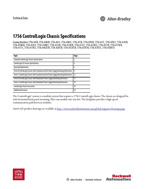
Technical Data1756 ControlLogix Chassis SpecificationsCatalog Numbers 1756-A4/B, 1756-A4K/B, 1756-A4/C, 1756-A4K/C, 1756-A7/B, 1756-A7K/B, 1756-A7/C, 1756-A7K/C, 1756-A10/B, 1756-A10K/B, 1756-A10/C, 1756-A10K/C, 1756-A13/B, 1756-A13K/B, 1756-A13/C, 1756-A13K/C, 1756-A17/B, 1756-A17K/B, 1756-A17/C, 1756-A17K/C, 1756-A4LXT/B, 1756-A5XT/B, 1756-A7LXT/B, 1756-A7XT/B, 1756-A7XT/C, 1756-A10XT/CThe ControlLogix® system is a modular system that requires a 1756 ControlLogix chassis. The chassis are designed for only horizontal back-panel mounting. Place any module into any slot. The backplane provides a high-speed communication path between modules.AutoCAD product drawings are available at /global/support/drawings.page.1756 ControlLogix Chassis SpecificationsStandard ControlLogix Chassis SpecificationsThe chassis backplane provides a high-speed communication path between modules and distributes power to each of the modules within the chassis.Technical Specifications - ControlLogix Standard Chassis (Series B)Technical Specifications - ControlLogix Standard Chassis (Series C)2Rockwell Automation Publication 1756-TD006F-EN-E - March 20171756 ControlLogix Chassis Specifications Environmental Specifications - ControlLogix Standard ChassisCertifications - ControlLogix Standard Chassis(1)See the Product Certification link at for Declarations of Conformity, Certificates, and other certification details.Rockwell Automation Publication 1756-TD006F-EN-E - March 201731756 ControlLogix Chassis SpecificationsControlLogix-XT Chassis SpecificationsThe ControlLogix-XT™ chassis support extreme temperature environments. The chassis are conformally coated for increased survivability in ISA G3 environments.Technical Specifications - ControlLogix-XT ChassisEnvironmental Specifications - ControlLogix-XT Chassis4Rockwell Automation Publication 1756-TD006F-EN-E - March 20171756 ControlLogix Chassis Specifications Certifications - ControlLogix-XT Chassis(1)See the Product Certification link at for Declarations of Conformity, Certificates, and other certification details.Rockwell Automation Publication 1756-TD006F-EN-E - March 201756Rockwell Automation Publication 1756-TD006F-EN-E - March 20171756 ControlLogix Chassis SpecificationsSpacing RequirementsWhen you mount a ControlLogix chassis with a standard power supply in an enclosure, follow these spacing requirements (series C chassis depicted).IMPORTANT The 1756-CPR2 cable has a bend radius of 12.7 cm (5.0 in.). The chassis must have a minimum clearance of 12.7 cm (5.0 in.)on the left side to route and connect the 1756-CPR2 cable. The redundant power supplies must have a minimum clearance of 12.7 cm (5.0in.) below the supply to route and connect the 1756-CPR2 cable.Rockwell Automation Publication 1756-TD006F-EN-E - March 201771756 ControlLogix Chassis SpecificationsWhen you mount a ControlLogix chassis with a redundant power supply and a chassis adapter in an enclosure, follow these spacing requirements (series C chassis depicted).Series C chassis offer these features:•Improved slot guidelines •Improved ventilation •Stronger mounting tabs•Additional hole in mounting tab •Additional ground screw(1) The measurements forsystems that use 1756-CPR2D or1756-CPR2U cables are 10.2 cm (4.0 in.).8Rockwell Automation Publication 1756-TD006F-EN-E - March 20171756 ControlLogix Chassis SpecificationsSeries B ControlLogix Chassis with Standard and Slim Power Supply Mounting DimensionsDimensions are in cm (in.).Chassis Common Dimensions1756-A4/B Chassis and Power Supply0.55 (0.217)Top Mounting Hole DiameterBottom Mounting Hole DiameterRight-side View of All Standard Chassis Right-side View of All ControlLogix-XT Chassis0.55(0.217)7.0 4.711756 ControlLogix Chassis Specifications1756-A7/B Chassis and Power Supply4.711756-A10/B Chassis and Power Supply5.71756-A13/B Chassis and Power Supply5.7Rockwell Automation Publication 1756-TD006F-EN-E - March 201791756 ControlLogix Chassis Specifications1756-A17/B Chassis and Power Supply4.71756-A4LXT/B Chassis and Power Supply10Rockwell Automation Publication 1756-TD006F-EN-E - March 20171756-A5XT/B Chassis and Power Supply1756-A7LXT/B Chassis and Power Supply1756-A7XT/B Chassis and Power SupplySeries C ControlLogix Chassis with Standard and Slim Power Supply Mounting DimensionsDimensions are in cm (in.).Chassis Common Dimensions1756-A4/C Chassis and Power Supply0.55 (0.217)Top Mounting Hole DiameterBottom Mounting Hole DiameterRight-side View of All Standard Chassis Right-side View of All ControlLogix-XT Chassis0.55(0.217)1756-A10/C Chassis and Power Supply1756-A13/C Chassis and Power Supply(27.76) 1756-A7XT/C Chassis and Power Supply1756-A10XT Chassis and Power SupplySeries B ControlLogix Chassis with Redundant Power Supply Mounting DimensionsDimensions are in cm (in.).Redundant Power SuppliesChassis Common DimensionsIMPORTANT The 1756-CPR2 cable has a bend radius of 12.7 cm (5.0 in.). The chassis must have a minimum clearance of 12.7 cm (5.0 in.) onthe left side to route and connect the 1756-CPR2 cable. The redundant power supplies must have a minimum clearance of12.7 cm (5.0 in.) below the supply to route and connect the 1756-CPR2 cable.1.1 (0.433)0.55 (0.217)Top Mounting Hole DiameterBottom Mounting Hole Diameter7.00.55 (0.217)Top MountingTab DiameterBottom Mounting Tab DiameterRight-side View of All Chassis0.78 (0.31)7.0 4.71756-A7/B Chassis and Chassis Adapter Module4.71756-A10/B Chassis and Chassis Adapter Module5.711756-A17/B Chassis and Chassis Adapter Module1756-A4LXT/B Chassis and Chassis Adapter5.714.76.297.07.3Series C ControlLogix Chassis with Redundant Power Supply Mounting DimensionsDimensions are in cm (in.).Redundant Power SuppliesChassis Common DimensionsIMPORTANT The 1756-CPR2 cable has a bend radius of 12.7 cm (5.0 in.). The chassis must have a minimum clearance of 12.7 cm (5.0 in.)on the left side to route and connect the 1756-CPR2 cable. The redundant power supplies must have a minimum clearance of12.7 cm (5.0 in.) below the supply to route and connect the 1756-CPR2 cable.1.1 (0.433)0.55 (0.217)Top Mounting Hole DiameterBottom Mounting Hole Diameter7.01.1 (0.433)0.55 (0.217)Top MountingTab DiameterBottom Mounting Tab DiameterRight-side View of All Chassis0.78 (0.31)0.55(0.217)1756-A7XT/C Chassis and Chassis Adapter7.3ControlLogix Chassis AccessoriesUse a slot filler module to fill empty slots.Additional ResourcesThese documents contain additional information concerning related products from Rockwell Automation.Y ou can view or download publications at /literature/. T o order paper copies of technical documentation, contact your local Allen-Bradley® distributor or Rockwell Automation sales representative.1756 ControlLogix Chassis Specifications Notes:Rockwell Automation Publication 1756-TD006F-EN-E - March 2017211756 ControlLogix Chassis SpecificationsNotes:22Rockwell Automation Publication 1756-TD006F-EN-E - March 20171756 ControlLogix Chassis Specifications Notes:Rockwell Automation Publication 1756-TD006F-EN-E - March 201723Rockwell Automation maintains current product environmental information on its website at /rockwellautomation/about-us/sustainability-ethics/product-environmental-compliance.page.Allen-Bradley, ControlLogix, ControlLogix-XT, LISTEN. THINK. SOLVE, Rockwell Automation, and Rockwell Software are trademarks of Rockwell Automation, Inc.Trademarks not belonging to Rockwell Automation are property of their respective companies.Rockwell Otomasyon Ticaret A.Ş., Kar Plaza İş Merkezi E Blok Kat:6 34752 İçerenköy, İstanbul, T el: +90 (216) 5698400Publication 1756-TD006F-EN-E - March 2017Supersedes Publication 1756-TD006E-EN-E - October 2014Copyright © 2017 Rockwell Automation, Inc. All rights reserved. Printed in the U.S.A.。
HVC135中文资料

HVC135Silicon Epitaxial Trench Pin Diode for Antenna SwitchingADE-208-818A (Z)Rev 1Feb. 2000 Features• Adopting the trench structure improves low capacitance.(C=0.6pF max)• Low forward resistance. (rf=2.0Ω max)• Low operation current.• Ultra small Flat Package (UFP) is suitable for surface mount design and stable rf characteristics in high frequency.Ordering InformationType ser Mark Package CodeHVC135P5UFPOutlineHVC1352Absolute Maximum Ratings (Ta = 25°C)ItemSymbol Value Unit Peak reverse voltage V RM 65V Reverse voltage V R 60V Forward current I F 100mA Power dissipation P d 150mW Junction temperature Tj 125°C Storage temperatureTstg-55 to +125°CElectrical Characteristics (Ta = 25°C)ItemSymbol Min Typ Max Unit Test Condition Reverse current I R ——0.1µA V R = 60V Forward voltage V F ——0.9V I F = 2 mACapacitance C ——0.6pF V R = 1V, f = 1 MHz Forward resistance r f —— 2.0ΩI F = 2mA, f = 100 MHzESD-Capability *1—100——VC = 200pF , Both forward and reverse direction 1 pulse.Notes 1. Failure criterion ; I R > 100nA at V R =60 VHVC135 Main Characteristic3HVC135Main Characteristic4HVC135 Package Dimensions5HVC1356Cautions1.Hitachi neither warrants nor grants licenses of any rights of Hitachi’s or any third party’s patent,copyright, trademark, or other intellectual property rights for information contained in this document.Hitachi bears no responsibility for problems that may arise with third party’s rights, including intellectual property rights, in connection with use of the information contained in this document.2.Products and product specifications may be subject to change without notice. Confirm that you have received the latest product standards or specifications before final design, purchase or use.3.Hitachi makes every attempt to ensure that its products are of high quality and reliability. However,contact Hitachi’s sales office before using the product in an application that demands especially high quality and reliability or where its failure or malfunction may directly threaten human life or cause risk of bodily injury, such as aerospace, aeronautics, nuclear power, combustion control, transportation,traffic, safety equipment or medical equipment for life support.4.Design your application so that the product is used within the ranges guaranteed by Hitachi particularly for maximum rating, operating supply voltage range, heat radiation characteristics, installationconditions and other characteristics. Hitachi bears no responsibility for failure or damage when used beyond the guaranteed ranges. Even within the guaranteed ranges, consider normally foreseeable failure rates or failure modes in semiconductor devices and employ systemic measures such as fail-safes, so that the equipment incorporating Hitachi product does not cause bodily injury, fire or other consequential damage due to operation of the Hitachi product.5.This product is not designed to be radiation resistant.6.No one is permitted to reproduce or duplicate, in any form, the whole or part of this document without written approval from Hitachi.7.Contact Hitachi’s sales office for any questions regarding this document or Hitachi semiconductor products.Hitachi, Ltd.Semiconductor & Integrated Circuits.Nippon Bldg., 2-6-2, Ohte-machi, Chiyoda-ku, Tokyo 100-0004, Japan Tel: Tokyo (03) 3270-2111 Fax: (03) 3270-5109Copyright ' Hitachi, Ltd., 2000. All rights reserved. Printed in Japan.Hitachi Asia Pte. Ltd.16 Collyer Quay #20-00Hitachi TowerSingapore 049318Tel: 535-2100Fax: 535-1533URLNorthAmerica : http:/Europe : /hel/ecg Asia (Singapore): .sg/grp3/sicd/index.htm Asia (Taiwan): /E/Product/SICD_Frame.htm Asia (HongKong): /eng/bo/grp3/index.htm Japan : http://www.hitachi.co.jp/Sicd/index.htmHitachi Asia Ltd.Taipei Branch Office3F, Hung Kuo Building. No.167, Tun-Hwa North Road, Taipei (105)Tel: <886> (2) 2718-3666Fax: <886> (2) 2718-8180Hitachi Asia (Hong Kong) Ltd.Group III (Electronic Components)7/F., North Tower, World Finance Centre,Harbour City, Canton Road, Tsim Sha Tsui,Kowloon, Hong Kong Tel: <852> (2) 735 9218Fax: <852> (2) 730 0281 Telex: 40815 HITEC HXHitachi Europe Ltd.Electronic Components Group.Whitebrook ParkLower Cookham Road MaidenheadBerkshire SL6 8YA, United Kingdom Tel: <44> (1628) 585000Fax: <44> (1628) 778322Hitachi Europe GmbHElectronic components Group Dornacher Stra§e 3D-85622 Feldkirchen, Munich GermanyTel: <49> (89) 9 9180-0Fax: <49> (89) 9 29 30 00Hitachi Semiconductor (America) Inc.179 East Tasman Drive,San Jose,CA 95134 Tel: <1> (408) 433-1990Fax: <1>(408) 433-0223For further information write to:。
微电脑控制器说明书
喷油螺杆空气压缩机微电脑控制器说明书上海康可尔压缩机有限公司SHANGHAI KANGKEER COMPRESSOR CO.LTD件号:119000-KE001 日期:2009-03-1螺杆压缩机控制器操作使用说明No. Contents Page142 3 5 技术参数2 保存/使用条件及说明3 注意事项 8 联网说明 8 1 2 3456 接线原理图 9 6 参数设置 47 英文说明 10 7 8英文版图表13811、技术参数1、开关量:8路光电隔离输入,5路继电器输出(最大7路);2、模拟量:1路4~20mA压力检测1路Pt100温度检测两组两路电流检测(含配套互感器两个);3、显示界面:最多同时显示48个16×16点汉字(4行,每行12个字)4、显示器控制器电源:AC18V 10VA 交流电源;总工作电流<150mA5、量程a)、电流测量范围:0~240A(更大电流检测需定制)。
分辨率0.1Ab)、温度测量范围:—20~120℃分辨率1℃c)、压力测量范围:0~1.60MPa 分辨率0.01MPad)、时间记录:0~999999小时分辨率1小时(按照小时记录)e)、输出继电器容量220V 5A(50万次寿命)6、相序保护:错相无法开机缺相保护时间小于1秒相不平衡保护时间16秒7、电机过载保护:电机电流大于额定电流的1.2倍时保护时间小于60秒;电机电流大于额定电流的1.3倍时保护时间小于48秒;电机电流大于额定电流的1.5倍时保护时间小于24秒;电机电流大于额定电流的1.6倍时保护时间小于8秒;电机电流大于额定电流的2.0倍时保护时间小于5秒;8、急停时间、超温、超压动作时间小于1秒。
9、温度校准精度≤0.5℃,压力传感器校准精度≤0.01MPa22、保存/使用条件1、保存环境:温度-20℃~+70℃干燥2、使用环境温度:-10℃~+60℃3、相对湿度:5%~95%,无结露4、其他要求:无腐蚀金属、破坏绝缘的气体存在,无显著的震动,无强磁场、电场。
sinomeasure-u-sin-ph8.5-lccn1-ph orp-controller-us

第十一章 通讯协议................................................................................36
V
第一章 产品概述
第一章 产品概述
仪器用于工业上 pH/mV ORP 及温度的测量,如:废水,纯净水,高 纯水,环境监测,食品生产过程等。
pH (0.00~+14.00)pH 0.01pH +0.01pH Pt1000/NTC10K (-10~+130)℃ (-10~+130)℃ 0.1℃ ±0.2℃
ORP (-2000~+2000)mV 1mV ±1mV
输入阻抗
>1012Ω
工作环境温度 储存环境温度
显示 pH/ORP 电流输出 1
温度电流输出 2 电流输出精确度
注意
系。
本手册内容如因功能升级等有修改时,恕不通知。 本手册内容我们力求正确无误,如果您发现有误,请与我们联
本手册内容严禁转载、复制。 本产品禁止使用在防爆场合。
版本
U-SIN-PH8.5-LCCN1 第一版 2021 年 6 月
I
确认包装内容
打开包装箱后,开始操作之前请先确认包装内容。如发现型号和数 量有误或者外观上有物理损坏时,请与本公司联系。
5.4.1 主画面.......................................................................... 10 5.4.2 电流 1 设定.................................................................. 11 5.4.3 电流 2 设定.................................................................. 12 5.4.4 继电器 1 设定.............................................................. 13 5.4.5 继电器 2 设定.............................................................. 13 5.4.6 继电器 3 设定.............................................................. 14 5.4.7 测量设定...................................................................... 15 5.4.8 温度设定...................................................................... 15
- 1、下载文档前请自行甄别文档内容的完整性,平台不提供额外的编辑、内容补充、找答案等附加服务。
- 2、"仅部分预览"的文档,不可在线预览部分如存在完整性等问题,可反馈申请退款(可完整预览的文档不适用该条件!)。
- 3、如文档侵犯您的权益,请联系客服反馈,我们会尽快为您处理(人工客服工作时间:9:00-18:30)。
1DS3600-1.2 September 1992PRELIMINARY INFORMATIONP10C68/P11C68(Previously PNC10C68 and PNC11C68)CMOS/SNOS NVSRAMHIGH PERFORMANCE 8 K x 8 NON-VOLATILE STATIC RAM(Supersedes DS3159-1.3, DS3160-1.3, DS3234-1.1, DS3235-1.1)The P10C68 and P11C68 are fast static RAMs (35 and 45ns) with a non-volatile electically-erasable PROM (EEPROM)cell incorporating in each static memory cell. The SRAM can be read and written an unlimited number of times while independent non-volatile data resides in PROM.On the P10C68 data may easily be transferred from the SRAM to the EEPROM (STORE) and from the EEPROM back to the SRAM ( RECALL) using the NE (bar) pin. The Store and Recall cycles are initiated through software sequences on the P11C68. These devices combine the high performance and ease of use of a fast SRAM with the data integrity of non-volatility.The P10C68 and P11C68 feature the industry standard pinout for non-volatile RAMs in a 28-pin 0.3-inch plastic and ceramic dual-in-line packages.FEATURESI Non-Volatile Data IntegrityI 10 year Data Retention in EEPROMI 35ns and 45ns Address and Chip Enable Access Times I 20ns and 25ns Output Enable Access I Unlimited Read and Write to SRAM I Unlimited Recall Cycles from EEPROM I 104 Store Cycles to EEPROM I Automatic Recall on Power up I Automatic Store Timing I Hardware Store Protection I Single 5V ± 10% OperationI Available in Standard Package 28-pin 0.3-inch DIL plastic and ceramic I Commercial and Industrial temperature ranges Pin Name FunctionA 0 - A 12Address inputs WWrite enable DQ 0 - DQ 7Data in/out E Chip enable G Output enable V CC Power (+5V)V SSGroundPin 1NE Non volatile enable P10C68Pin 1N/C No connection P11C6812345678910111213142827262524232221201918171615V W NC A A A G A E DQ DQ DQ DQ DQ 76543891110CC NE A A A A A A A A A DQ DQ DQ V 1276543210012ssFigure 1. Pin connections - top view.ORDERING INFORMATION (See back page)F igure 2. Logic block diagram. 23Value ParameterSupply voltageInput logic '1' voltage Input logic '0' voltageAmbient operating temperaturecommercial industrialSymbolV CC V IH V IL T amb T ambMin.2.2V SS -0.50-40ConditionsAll inputs All inputsMax.V CC +0.50.8+70+85Typ.5.0DC OPERATING CONDITIONSDC ELECTRICAL CHARACTERISTICS Commercial temperature rangeTest conditions (unless otherwise stated):Tamb = 0°C to 70°C, Vcc = +5V (See notes 1, 2 and 3)CharacteristicAverage power supply currentAverage power supply current during STORE cycleAverage power supply current (standby, cycling TTL input levels)Average power supply current(standby, stable CMOS input levels)Input leakage current (any input)Off state output leakage current Output logic '1' voltage Output voltage '0' voltageSymbolI CC1I CC2I SB1I SB2I ILK I OLK V OH V OLValueUnitsmA mA mAmA mAmAµA µA V VConditionst AVAV = 35ns t AVAV = 45nsAll inputs at V IN ≤ 0.2V t AVAV = 35ns t AVAV = 45nsE(bar) ≥V IH , all other inputs cyclingE (bar)≥(V CC -0.2V), all other inputs at V IN ≤0.2V or ≥(V CC -0.2V)V CC = max, V IN = V SS to V CC V CC = max, V IN = V SS to V CC I OUT = 4mA I OUT = 8mAMax.75655023201±1±50.4Min.2.4NOTES 1.I CC1 is dependent on output loading and cycle rate. The specified values are obtained with outputs unloaded.2.Bringing E (bar) ≥ V IH will not produce standby currents levels until any non-volatile cycle in progress has timed out. SeeMode Selection table.3.I CC2 is the average current required for the duration of the STORE cycle (t STORE ) after the sequence that initiates thecycle.ABSOLUTE MAXIMUM RATINGSVoltage on typical input relative to VSS-0.6V to 7.0V Voltage on DQ0-7 and G(bar)-0.5V to (Vcc + 0.5V)Temperature under Bias -55°C to + 125°C Storage temperature -65°C to + 150°C Power dissipation 1W DC output current15mA(one output at a time, one second duration)NOTEStresses greater than those listed in the Absolute Maximum Ratings may cause permanent damage to the device. These are stress ratings only; functional operation of the device at any other conditions than those indicated in the operational sections of the specification is not implied.Exposure to absolute maximum ratings conditions for extended periods may affect reliability.Units V V VoC oC4CharacteristicAverage power supply currentAverage power supply current during STORE cycleAverage power supply current (standby, cycling TTL input levels)Average power supply current(standby, stable CMOS input levels)Input leakage current (any input)Off state output leakage current Output logic '1' voltage Output voltage '0' voltageIndustrial temperature rangeTest conditions (unless otherwise stated):Tamb = -40˚C to 70˚C, Vcc = +5V ± 10% (See notes 4, 5 and 6)SymbolI CC1I CC2I SB1I SB2I ILK I OLK V OH V OLValueUnitsmA mA mAmA mAmAµA µA V VConditionst AVAV = 35ns t AVAV = 45nsAll inputs at V IN ≤ 0.2V t AVAV = 35ns t AVAV = 45nsE(bar) ≥V IH , all other inputs cyclingE (bar)≥(V CC -0.2V), all other inputs at V IN ≤0.2V or ≥(V CC -0.2V)V CC = max, V IN = V SS to V CC V CC = max, V IN = V SS to V CC I OUT = 4mA I OUT = 8mAMax.80755027231±1±50.4Min.2.4Input pulse levelsInput rise and fall timesInput and output timing reference levels Output loadV SS to 3V ≤5ns 1.5VSee Figure 3AC TEST CONDITIONSCAPACITANCE T amb = 25°C, f = 1.0MHz (see note 7)Parameter Input capacitance Output capacitanceSymbol C IN COUTUnits pF pFMax.57Conditions ∆V=0 to 3V ∆V=0 to 3VNOTE7. These parameters are characterised but not 100% tested.NOTES 4.I CC1 is dependent on output loading and cycle rate. The specified values are obtained with outputs unloaded.5.Bringing E (bar) ≥ V IH will not produce standby currents levels until any non-volatile cycle in progress has timed out. SeeMode Selection table.6.I CC2 is the average current required for the duration of the STORE cycle (t STORE ) after the sequence that initiates thecycle.Figure 3. AC output loading.5SRAM MEMORY OPERATIONTest conditions (unless otherwise stated):Commercial and Industrial Temperature RangeTamb = -40°C to + 85°C, Vcc = + 5V ± 10%READ CYCLES 1 AND 2 (See note 8)NOTES 8. E (bar), G (bar) and W (bar) must make the transition between VIH(min) to VIL(max), or VIL(max) to VIH(min) in amonotonic fashion. NE (bar) must be ≥ VIH during entire cycle.9.For READ CYCLE 1 and 2, W (bar) and NE (bar) must be high for entire cycle.10.Device is continuously selected with E (bar) low, and G (bar) low.11.Measured ±200mV from steady state output voltage. Load capacitance is 5pF.12.Parameter guaranteed but not tested.Figure 4. READ CYCLE 1 timing diagram (see notes 9 and 10).Standard t ELQV t AVAV t AVQV t GLQV t AXQX t ELQX t EHQZ t GLQX t GHQZt ELICCHt EHICCL t WHQVAlternativet ACS t RC t AA t OE t OH t LZ t OHZ t OLZ t HZ t PA t PS t WRParameter Chip enable access time Read cycle timeAddress access timeOutput enable to data validOutput hold after address change Chip enable to output active Chip disable to output inactive Output enable to output active Outout disable to output inactive Chip enable to power active Chip disable to power standby Write recovery timeUnits ns ns ns ns ns ns ns ns ns ns ns nsNotes91011111212P10C68-45P11C68-45P10C68-35P11C68-35SymbolMin.4555Max.45452525202555Min.3555Max.353520201525456WRITE CYCLE 1 : W (BAR) CONTROLLED (See notes 8 and 13)Commercial and Industrial Temperature RangeF igure 5. READ CYCLE 2 timing diagram (see note 9).Standard t AVAV t WLWH t ELWH t DVWH t WHDX t AVWH t AVWL t WHAX t WLQZ t WHQZAlternativet WC t WP t CW t DW t DH t AW t AS t WR t WZ t OWParameterWrite cycle time Write pulse widthChip enable to end of write Data set-up to end of write Data hold after end of write Address set-up to end of write Address set-up to start of write Address hold after end of write Write enable to output disable Output active after end of writeUnitsns ns ns ns ns ns ns ns ns nsNotes11, 14P10C68-45P11C68-45P10C68-35P11C68-35SymbolMin.45353530035005Max.35Min.45353530035005Max.35NOTES 13. E (bar) or W (bar) must be ≥ VIH during address transitions.14.If W (bar) is low when E (bar) goes low, the outputs remain in the high impedance state.7F igure 6. WRITE CYCLE 1: W (bar) controlled timing diagram (see notes 8 and 13).Standard t AVAV t WLEH t ELEH t DVEH t EHDX t AVEH t EHAX t AVWLAlternativet WC t WP t CW t DW t DH t AW t WR t ASParameterWrite cycle time Write pulse widthChip enable to end of write Data set-up to end of write Data hold after end of write Address set-up to end of write Address hold after end of write Address set-up to start of writeUnitsns ns ns ns ns ns ns nsNotesP10C68-45P11C68-45P10C68-35P11C68-35SymbolMin.4535353003500Max.Min.4535353003500Max.WRITE CYCLE 2 : E (BAR) CONTROLLED (See notes 8 and 13)F igure 7. WRITE CYCLE 2: E (bar) controlled timing diagram (see notes 8 and 13).8Figure 8. Automatic RECALL and STORE inhibit.NON-VOLATILE MEMORY OPERATION OF P10C68MODE SELECTIONW X H L H L L HE H L L L L L LG X L X L H L HNE X H H L L L XPower Standby Active Active Active I CC2ActiveModeNot selected Read RAM Write RAMNon-volatile recall (Note 15)Non-volatile store No operationNOTE 15.An automatic RECALL also takes place on chip power-up, starting when Vcc exceeds 3.3V, and taking t RECALL from thetime at which Vcc exceeds 3.3V. Vcc must not drop below 3.3V once it has exceeded it for the RECALL to function properly.Standard t WLQX t GHNL t NLWL t WLNH t ELWLAlternative t STORE t WCParameterStore cycle timeOutput disable set-up to NE (bar) fall Non-volatile set-up to write low Write low to NE (bar) rise Chip enable SET-UPSymbolNotes1718Unitsms ns ns ns nsMin.00450Max.10Min.00450Max.10STORE CYCLE 1 : W (BAR) CONTROLLED (See note 16)P10C68-35P10C68-459STORE CYCLE 2 : E (BAR) CONTROLLED (See note 13)Standard t ELQX1t NLEL t WLEL t ELNH t GHELAlternative t STORE t WCParameterStore cycle timeNE (bar) set-up to chip enableWrite enable wet-up to chip enable Chip enable to NE (bar) riseOutput disable set-up to E (bar) fallSymbolNotes1718Unitsms ns ns ns nsMin.00450Max.10Min.00450P10C68-35P10C68-45Max.10NOTES16. E (bar), G (bar), NE (bar) and W (bar) must make the transition between VIH(max) to VIL(max), or VIL(max) to VIH(min) in a monotonic fashion.17. Measured with W (bar) and NE (bar) both returned high, and G (bar) returned low. Note that store cycles are inhibited/aborted by Vcc <3.3V (STORE inhibit).18. Once twc has been satisfied by NE (bar), G (bar), W (bar) and E (bar) the store cycle is completed automatically, ignoring allinputs. Any of NE (bar), G (bar), W (bar) or E (bar) may be used to terminate the store initiation cycle.Figure 9. STORE CYCLE 1: W (bar) controlled timing diagram (see note 16).Figure 10. STORE CYCLE 2: E (bar) controlled timing diagram (see note 16).10Standard t NLQX t NLNH t GLNL t WHNL t ELNL t NLQZAlternative t RECALL t RCParameterRecall cycle timeRecall initiation cycle time Output enable set-up Write enable set-up Chip enable set-upNE (bar) fall to output inactiveUnitsµs µs ns ns ns nsNotes1920SymbolMin.25000Max.2025Min.25000Max.2025P10C68-45P10C68-35P10C68 RECALL CYCLE 1 : NE (BAR) CONTROLLED (See note 16)P10C68 RECALL CYCLE 3 : G (BAR) CONTROLLED (See note 16)Alternative t RECALL t RCParameterRecall cycle timeRecall initiation cycle time NE (bar) set-up Write enable set-up Chip enable set-upUnitsµs ns ns ns nsNotes1920SymbolMin.25000Max.20Min.25000Max.20P10C68-45P10C68-35Standard t GLQX2t GLNH t NLGL t WHGL t ELGLNOTES 19.Measured with W (bar) and NE (bar) both returned high, and G (bar) returned low. Address transitions may not occur onany address pin during this time.20.Once t RC has been satisfied by NE (bar), G (bar), W (bar) and E (bar) the RECALL cycle is completed automatically. Anyof NE (bar), G (bar) or E (bar) may be used to terminate the RECALL initiation cycle.P10C68 RECALL CYCLE 2 : E (BAR) CONTROLLED (See note 16)Alternative t RECALL t RCParameterRecall cycle timeRecall initiation cycle time NE (bar) set-upOutput enable set-up Write enable set-upUnitsµs ns ns ns nsNotes1920SymbolMin.25000Max.20Min.25000Max.20P10C68-45P10C68-35Standard t ELQX2t ELNH t NLEL t GLEL t WHELP10C68/P11C6811Figure 11. P10C68 RECALL CYCLE 1: NE (bar) controlled timing diagram (see note 16).Figure 12. P10C68 RECALL CYCLE 2: E (bar) controlled timing diagram (see note 16).Figure 13. P10C68 RECALL CYCLE 3: E (bar) controlled timing diagram (see note 16).P10C68/P11C6812Notes2221, 2221, 2221, 2221, 2221, 222021, 2221, 2221, 2221, 2221, 2221Power Standby Active Active ActiveI CC2Active I/O Output High Z Output data Input Data Output Data Output Data Output Data Output Data Output Data Output High Z Output Data Output Data Output Data Output Data Output Data Output High ZModeNot selected Read RAM Write RAM Read RAM Read RAM Read RAM Read RAM Read RAMNon-volatile STORE Read RAM Read RAM Read RAM Read RAM Read RAMNon-volatile RECALLA 12-A 0 (hex)X X X 000015550AAA 1FFF 10F00F0F000015550AAA 1FFF 10F00F0EE H L L LLW X H L HHStandard t AVAVt AXAV t AVQZ t AVEL t ELEH t EHAXAlternativet ACSt SKEW t ELQZt STORE t RECALL t AE t EP t EA ParameterRead cycle timeSkew between sequentially adjacent addressesAddress valid to output inactive Store cycle time Recall cycle timeAddress set-up to chip enable Chip enable pulse widthChip disable to address changeUnitsns ns ns ms µs ns ns nsNotes23252626, 30272727SymbolMin.450450Max.5751020Min.350350Max.5751020P11C68-45P11C68-35NOTES 23.Skew spec may be avoided by using E (bar) (STORE/RECALL CYCLE 2).24.W (bar) ≥V IH during entire address sequence to initiate a non-volatile cycle.Required address sequences are shown in the Mode Selection table.25.Once the software STORE or RECALL cycle is initiated, it completes automatically, ignoring all inputs.26.Measured with W (bar) high, G (bar) low and E (bar) low. Note that STORE cycles (but not RECALLS) are aborted by Vcc< 3.3V (STORE Inhibit).27. E (bar) must make the transition between V IH (max) to V IL (max), or V IL (max) to V IH (min) in a monotonic fashion.28.Chip is continuously selected with E (bar) low.29.Addresses 1 through 6 are found in the Mode Selection table. Address 6 determines whether the P11C68 performs aSTORE or RECALL. A RECALL cycle is performed automatically at power up when V CC exceeds 3.3V. V CC must not drop below 3.3V once it has exceeded it for the RECALL to function properly, t RECALL is measured from the point at which V CC exceeds 3.3V.30.Address transitions may not occur on any address pin during this time.NOTES 21.The six consecutive addresses must be in order listed - (0000, 1555, 0AAA, 1FFF, 10F0, 0F0F) for a STORE cycle or(0000, 1555, 0AAA, 1FFF, 10F0, 0F0E) for a RECALL cycle. W (bar) must be high during all six consecutive cycles. See STORE CYCLE and RECALL CYCLE tables and diagrams for further details.22.I/O state assumes that G (bar) ≥V IL . Activation of non-volatile cycles does not depend on the state of G (bar).STORE / RECALL CYCLES 1 AND 2 (See notes 24 and 29)NON-VOLATILE MEMORY OPERATION OF P11C68MODE SELECTIONP10C68/P11C6813OPERATING NOTESNote: References to NE (bar) should be taken as applying to P10C68 only and can be ignored for P11C68.The devices have two separate modes of operation: SRAM mode and non-volatile mode. In SRAM mode, the memory operates as an ordinary static RAM. While in non-volatile mode, data is transferred in parallel from SRAM to EEPROM or from EEPROM to SRAM.SRAM READThe devices perform a read cycle when ever E (bar) and G (bar) are LOW and NE (bar) and W (bar) are H IGH. The address specified by the thirteen address pins A 0-12 determine which of the 8192 data bytes will be accessed. When the READ is initiated by an address transistion, the outputs will be valid after a delay of t AVQV (READ CYCLE 1).If the READ is initiated by E (bar) or G (bar), the outputs will be valid at t ELQV or t GLQV , whichever is later. (READ CYCLE 2).The data outputs will repeatedly respond to address changes within the t AVQV access time without the need for transitions on any control input pins and will remain valid until another address change or until E (bar) or G (bar) is brought HIGH or W (bar) or NE (bar) is brought LOW.SRAM WRITEA write cycle is performed whenever E (bar) and W (bar)are LOW and NE (bar) is HIGH. The address inputs must be stable prior to entering the WRITE cycle and must remain stable until either E (bar) or W (bar) go HIGH at the end of the cycle. The data on the eight pins DQ 0-7, will be written into the memory location specified by the address inputs if valid t DVWH before the end of a W (bar) controlled WRITE or t DVEH before the end of an E (bar) controlled WRITE.Figure 15. STORE/RECALL cycle 2. E (bar) controlled timing diagram (see notes 22, 25 and 27).Figure 14. STORE/RECALL cycle 1. Address controlled timing diagram (see notes 22, 26 and 27).P10C68/P11C6814It is recommended that G (bar) be kept HIGH during theentire WRITE cycle to avoid data bus contention on the common I/O lines. If G (bar) is left LOW, internal circuitry will turn off the output buffers t WHQZ after W (bar) goes LOW.Non-Volatile STORE - P10C68A STORE cycle is performed when NE, (bar) E (bar) and W (bar) are LOW and G (bar) is HIGH. While any sequence to achieve this state will initiate a STORE, only W(bar) initiation (STORE CYCLE 1) and E (bar) initiation (STORE CYCLE 2) are practical without risking an unintentional SRAM WRITE that would disturb SRAM data. During the STORE cycle, previous non-volatile data is erased and the SRAM contents are then programmed into non-volatile elements. Once a STORE cycle is initiated, further input and output is disabled and the DQ0-7 pins are tri-stated until the cycle is completed.If E (bar) and G (bar) are LOW and W (bar) and NE (bar) are HIGH at the end of the cycle, a READ will be performed and the outputs will go active, signalling the end of the STORE.The P10C68 will not be activated into either a STORE or RECALL cycle by the software sequence required for the P11C68.Hardware Protect - P10C68The P10C68 offers two levels of protection to suppress inadvertent STORE cycles. If the clock signals remain in the STORE condition at the end of a STORE cycle, a second STORE cycle will not be started. The STORE will be initiated only after a HIGH to LOW transition on NE (bar)Because the STORE cycle is initiated by an NE (bar) transition, powering-up the chip with NE (bar) Low will not initiate a STORE cycle either.In addition to multi-trigger protection, the P10C68 offers hardware protection through Vcc Sense. A STORE cycle will not be initiated, and one in progress will discontinue, if Vcc goes below 3.3V.Non-Volatile RECALL - P10C68A RECALL cycle is performed when E (bar), G (bar) and NE (bar) are LOW and W (bar) is HIGH. Like the STORE cycle, RECALL is initiated when the last of the four clock signals goes to the RECALL state. Once initiated, the RECALL cycle will take t NLQX to complete, during which all inputs are ignored. When the RECALL completes, any READ or WRITE state on the input pins will take effect.Internally, RECALL is a two step procedure. First the SRAM data is cleared and second, the non-volatile information is transferred into the SRAM cells. The RECALL operation in no way alters the data in the non-volatile cells. The non-volatile data can be recalled an unlimited number of times. Address transitions may not occur during the RECALL cycle. Like the STORE cycle, a transition must occur on the NE (bar) pin to cause a RECALL, preventing inadvertent multi-triggering. On power-up, once Vcc exceeds Vcc sense voltage of 3.3V, a RECALL cycle is automatically initiated. The voltage on the Vcc pin must not drop below 3.3V once it has risen above it in order for the RECALL to operate properly. Due to the automatic RECALL, SRAM operation cannot commence until t NLQX after Vcc exceeds 3.3V.The P11C68 STORE cycle is initiated by executing sequential READ cycles from six specific address locations. By relying on READ cycles only, the P11C68 implements non-volatile operation while remaining pin-for-pin compatible with standard 8Kx8 SRAMs. During the STORE cycle, an erase of the previous non-volatile data is first performed, followed by a program of the non-volatile elements. The program operation copies the SRAM data into non-volatile storage. Once a STORE cycle is initiated, further input and output are disabled until the cycle is completed. Because a sequence of addresses is used for STORE initiation, it is critical that no invalid address states intervene in the sequence or the sequence will be aborted. The maximum skew between address inputs A0-12 for each address state is t SKEW (STORE CYCLE 1).If t SKEW is exceeded it is possible that the transitional data state will be interpreted as a valid address and the sequence will be aborted. If E (bar) controlled READ cycles are used for the sequence (STORE CYCLE 2), address skew is no longer a concern.To enable the STORE cycle the following READ sequence must be performed.1. Read address 0000 (hex) Valid READ2. Read address 1555 (hex) Valid READ3. Read address 0AAA (hex) Valid READ4. Read address 1FFF (hex) Valid READ5. Read address 10F0 (hex) Valid READ6. Read address 0F0F (hex) Initiate STORE CycleOnce the sixth address in the sequence has been entered, the STORE cycle will commence and the chip will be disabled. It is important that READ cycles and not WRITE cycles be used in the sequence, although it is not necessary that G (bar) be LOW for the sequence to be valid. After the t STORE cycle time has been fulfilled, the SRAM will again be activated for READ and WRITE operation.Once the first of the six reads has taken place, the read sequence must either complete or terminate with an incorrect address (other than 0000 hex) before it may be started anew.The P11C68 offers hardware protection against inadvertent STORE cycles through Vcc Sense. A STORE cycle will not be initiated, and one in progress will discontinue, if Vcc goes below 3.3V.A RECALL of the EEPROM data into the SRAM is initiated with a sequence of READ operations in a manner similar to the STORE initiation. To initiate the RECALL cycle the following sequence of READ operations must be performed:1. Read address 0000 (hex) Valid READ2. Read address 1555 (hex) Valid READ3. Read address 0AAA (hex) Valid READ4. Read address 1FFF (hex) Valid READ5. Read address 10F0 (hex) Valid READ6. Read address 0F0E (hex) Initiate RECALL CycleInternally, RECALL is a two step procedure. First, the SRAM data is cleared and second the non-volatile information is transferred into the SRAM cells. The RECALL operation in no way alters the data in the EEPROM cells. The non-volatile data can be recalled an unlimited number of times. Address transitions may not occur during the RECALL cycle.P10C68/P11C6815On power-up, once Vcc exceeds the Vcc sense voltage of 3.3V, a RECALL cycle is automatically initiated. The voltage on the Vcc pin must not drop below 3.3V once it has risen above it in order for the RECALL to operate properly. Due to this automatic RECALL, SRAM operation cannot commence until t RECALL after Vcc exceeds 3.3V.The automatic RECALL feature can be adversely affected by factors such as supply rise time, temperature and elapsed time since the last STORE cycle. For this reason it is recommended that the user initiate a RECALL cycle after power-up for critical applications.PACKAGE DETAILSDimensions are shown thus: mm (in). For further package information please contact your local Customer Service Centre.Figure 16, 28-lead sidebrazed ceramic DIL (0.3in) DCBFigure 17. 28 plastic DIL Package (0.3in) DPBP10C68/P11C6816HEADQUARTERS OPERATIONS GEC PLESSEY SEMICONDUCTORS Cheney Manor, Swindon,Wiltshire SN2 2QW, United Kingdom.Tel: (0793) 518000 Tx: 449637Fax: (0793) 518411GEC PLESSEY SEMICONDUCTORSSequoia Research Park, 1500 Green Hills Road,Scotts Valley, California 95066,United States of America. Tel (408) 438 2900ITT Telex: 4940840 Fax: (408) 438 5576CUSTOMER SERVICE CENTRES•FRANCE & BENELUX Les Ulis Cedex Tel: (1) 64 46 23 45 Tx: 602858F Fax : (1) 64 46 06 07•GERMANY Munich Tel: (089) 3609 06-0 Tx: 523980 Fax : (089) 3609 06-55 •ITALY Milan Tel: (02) 66040867 Fax: (02) 66040993 •JAPAN Tokyo Tel: (03) 3296-0281 Fax: (03) 3296-0228•NORTH AMERICA Integrated Circuits and Microwave Products, Scotts Valley, USA Tel (408) 438 2900 ITT Tx: 4940840 Fax: (408) 438 7023.Hybrid Products, Farmingdale, USA Tel (516) 293 8686Fax: (516) 293 0061.•SOUTH EAST ASIA Singapore Tel: 2919291 Fax: 2916455•SWEDENJohanneshov Tel: 46 8 702 97 70 Fax: 46 8 640 47 36 •UNITED KINGDOM & SCANDINAVIASwindon Tel: (0793) 518510 Tx: 444410 Fax : (0793) 518582These are supported by Agents and Distributors in major countries world-wide.© GEC Plessey Semiconductors Year Publication No. XX XXXX Issue No. X.X Month YearThis publication is issued to provide information only which (unless agreed by the Company in writing) may not be used, applied or reproduced for any purpose nor form part of any order or contract nor to be regarded as a representation relating to the products or services concerned. No warranty or guarantee express or implied is made regarding the capability, performance or suitability of any product or service.The Company reserves the right to alter without prior knowledge the specification, design or price of any product or service. Information concerning possible methods of use is provided as a guide only anddoes not constitute any guarantee that such methods of use will be satisfactory in a specific piece of equipment. It is the user's responsibility to fully determine the performance and suitability of anyequipment using such information and to ensure that any publication or data used is up to date and has not been superseded. These products are not suitable for use in any medical products whose failure toperform may result in significant injury or death to the user. All products and materials are sold and services provided subject to the Company's conditions of sale, which are available on request.Information relating to products and services furnished herein by Zarlink Semiconductor Inc. trading as Zarlink Semiconductor or its subsidiaries (collectively “ Zarlink ” )is believed to be reliable. However, Zarlink assumes no liability for errors that may appear in this publication, or for liability otherwise arising from the application or use of any such information, product or service or for any infringement of patents or other intellectual property rights owned by third parties which may result from such application or use. Neither the supply of such information or purchase of product or service conveys any license, either express or implied, under patents or other intellectual property rights owned by Zarlink or licensed from third parties by Zarlink, whatsoever. Purchasers of products are also hereby notified that the use of product in certain ways or in combination with Zarlink, or non-Zarlink furnished goods or services may infringe patents or other intellectual property rights owned by Zarlink.This publication is issued to provide information only and (unless agreed by Zarlink in writing) may not be used, applied or reproduced for any purpose nor form part of any order or contract nor to be regarded as a representation relating to the products or services concerned. The products, their specifications, services and other information appearing in this publication are subject to change by Zarlink without notice. No warranty or guarantee express or implied is made regarding the capability,performance or suitability of any product or service. Information concerning possible methods of use is provided as a guide only and does not constitute any guarantee that such methods of use will be satisfactory in a specific piece of equipment. It is the user ’ s responsibility to fully determine the performance and suitability of any equipment using such information and to ensure that any publication or data used is up to date and has not been superseded. Manufacturing does not necessarily include testing of all functions or parameters. These products are not suitable for use in any medical products whose failure to perform may result in significant injury or death to the user. All products and materials are sold and services provided subject to Zarlink ’ s conditions of sale which are available on request.Purchase of Zarlink s I 2 C components conveys a licence under the Philips I 2 C Patent rights to use these components in and I 2 C System, provided that the system conforms to the I 2 C Standard Specification as defined by Philips.Zarlink and the Zarlink Semiconductor logo are trademarks of Zarlink Semiconductor Inc.Copyright 2001, Zarlink Semiconductor Inc. All Rights Reserved.TECHNICAL DOCUMENTATION - NOT FOR RESALEFor more information about all Zarlink productsvisit our Web Site at。