CDS6-147b(最新便携规格书)
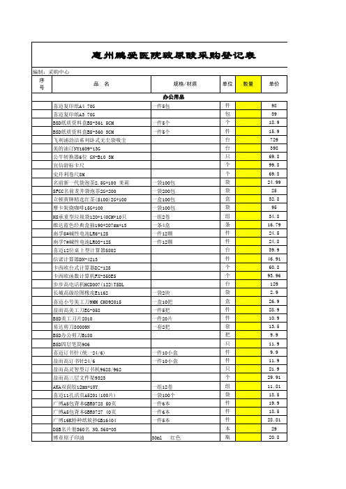
惠州鹏爱医院玻尿酸采购登记表
40*30*8cm 按设计要求 按设计要求 GM-K1-40CSW QL2-MC 5L*2瓶 348mL*24瓶 VPL-EX245 VPL-EX273 100寸红叶 100寸绿叶 DELL 3010MT DELL7010MT JP-194 4200*1200*725
个 个 册 台 台 台 件 件 台 台 套 套 台 台 张 平方 平方 平方 平方 平方 平方 块 瓶 瓶 提 件 个 个 包 双 双
HP 1536DNF HP 1213 HP 1108 HP 5200L 松下 7006CN 松下TTR57E TSC T4403E 50*30哑银双排 维融 8100 诺为 N31 诺为 N92 罗技 R400 TP-link842 TP-link SF1005+ TP-linkSF1008+ TP-linkSF1016D TP-linkSF1024D
TP-linkSF1048S TL-SG1024DT KST 32G KST 8G KST 4G 金士顿16G(原装) 金士顿DDR2 800 2G 金士顿DDR3 1333 2G 金士顿DDR3 1333 4G 威刚DDR3 1333 8G 金士顿KST DDR3 1600 2G 173 KST DDR3 1600 4G VCOM网线 电话 TP-linkWN851N 5米 TCL 4芯300米 金贝视75-5 三保568 中诺 美网s2000 2TB SATA6GB/S 64M 西数1000G(原装) 西数2T TP842 300M 新贵 200米/卷
个 支 个 支 个 支 个 支 个 支 个 支 个 支 个 支 个 支 盒 个 支 张 张 张 张 张 张 张 张 张 张 张 斤 斤 桶 桶 套 套 件 件 床 床 台 台 台 台 台
硫化镉光敏电阻器(PGM)规格书
Ø0.6 17.5
环氧树脂封装 (PGM 20mm) 外观
环氧树脂封装 (PGM 20mm) 尺寸
Plastic Case Ø 22 5 Epoxy Resin 17.5
金属外壳封装 (PGM 20mm) 外观
备注: 尺寸的单位是 (mm), 且各部分尺寸不一。
金属外壳封装 (PGM 20mm) 尺寸
金属外壳封装 (PGM 5mm) 外观
备注: 尺寸的单位是 (mm), 且各部分尺寸不一。
金属外壳封装 (PGM 5mm) 尺寸
Ø 0.5
04 of 07
德键电子工业股份有限公司
Version 2014
34±2
PGM5**** series Epoxy resin package
4.3±0.2
2.4Max
5mm CDS 光敏电阻器 (PGM55**-MP) 系列 电子特性
型号 最大电压 (VDC) 最大功率 (mW) 环境温度 (°C) 光谱峰值 (nm) 亮电阻 (10Lx)(KΩ) 暗电阻 (MΩ)min γ min 响应时间(ms) 上升 下降
PGM5506-MP PGM5516-MP PGM5526-MP PGM5537-MP PGM5539-MP PGM5549-MP
CdS CdSe Cd(S.Se)
600 700 800 Wavelength(nm)
900
1000
(PGM) 光谱响应
02 of 07
德键电子工业股份有限公司
Version 2014
TOKEN
CDS 光敏 - PGM 系列 物理和环境特性
项 目 可焊性
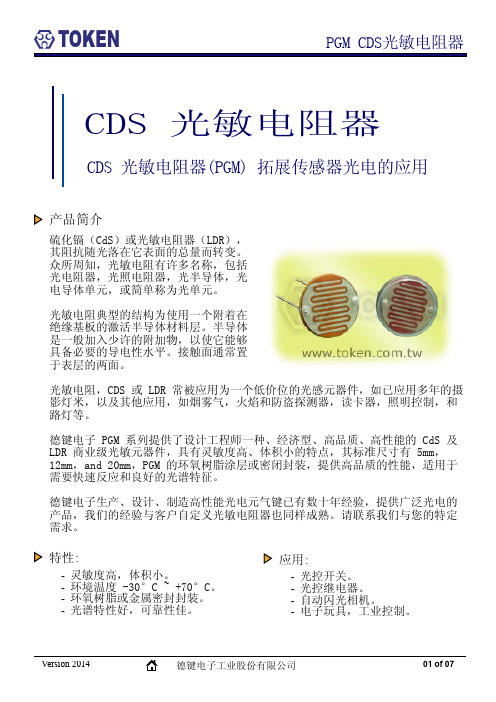
PGM CDS光敏电阻器
测试方法 在温度为 230±5°C 时 将引脚端浸入焊锡液中 2±0.5秒(针脚端远离焊锡面5mm). 温度变化值 温度变化: 低(-40°C) - 高(+60°C) 连续 5 个回 合 持续时间:30分钟 湿度和热度 1. 将测试盒设置成:60±5°C; 湿度:90-95%; 日照强度:0勒克斯; 持续时间:100小时 2. 在正常的温度和湿度下放置24小时后取走 温度系数 在 25±5°C 条件下日照强度:150勒克斯 (在额定功率下) 持续时间:600小时 金属丝弯曲强度 将引脚固定,另一端向相反方向弯曲90° 振动 频率:50Hz 振幅:1. 5mm 用法:平行陶瓷层对着陶瓷层持续时间:2小时
MOSFET datasheet 参数理解及其主要特性
电源应用中 Mosfet 驱动电路设计参考
一、驱动过程原理
来源:电源谷 作者:Blash
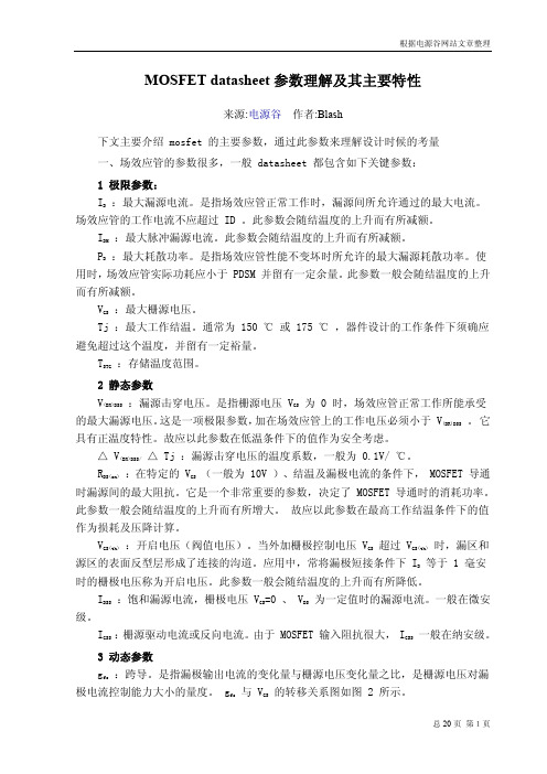
驱动设计是 MOSFET 应用的重点之一。而 MOSFET 驱动过程特性的理解将会 有助于此方面的正确应用。
MOSFET 的栅极驱动过程可以简单理解为驱动电源对 MOSFET 输入电容的充放 电过程。其极间电容效应如本站文章“ DATASHEET 参数及基本特性” 中示意图所示。 器件规格书目所提供的极间电容值是在一定条件下得到的静态参数。而在实际应用,这 些电容的参数是温度及电压的非线性函数关系,而且受米勒效应的影响,总的动态输入 电容将比总静态电容大得多。这些都给栅极驱动的准确分析带来很大困难。但从应用角 度,了解其驱动过程的特性是必须的。
IAR :雪崩电流。 EAR :重复雪崩击穿能量。 5 热阻
:结点到外壳的热阻。它表明当耗散一个给定的功率时,结温与外壳温度之间
的差值大小。公式表达⊿ t = PD*
。
:外壳到散热器的热阻,意义同上。
:结点到周围环境的热阻,意义同上。
6 体内二极管参数 IS :连续最大续流电流(从源极)。 ISM :脉冲最大续流电流(从源极)。 VSD :正向导通压降。 Trr :反向恢复时间。 Qrr :反向恢复充电电量。 Ton :正向导通时间。(基本可以忽略不计)。
t 3 ~ t 4 时期. t 3 时刻,在 IG 的继
所需驱动电量: △ Q t 0 ~ t 1 = (t 1-t 0 )IG = VG(th)Ciss ≈ VG(th)CGS 所需驱动电流: IG = VG(th)Ciss / (t1-t0 ) 栅极电压上升率: dVGS /dt= IG /Ciss ≈ IG / CGS 现实使用中(驱动电压近似恒压源), 如图 7 示, VGS 呈指数上升,时间常数 t 1 = RG(CGS + CGD1) . t1~t2 时期 。 t1 时刻 MOSFET 被打 开,在 t1~t2 期间 IG 给 Ciss 继续充电。栅 极电压 VGS 继续上升,机理跟前一阶段完全 一样,公式参考如上。此时器件进入了饱 和区(进入此区的条件是 VDS>(VDS(sat)=VGS-Vth) ,漏极电流 iD 从 t1 时 刻起依 VGS 按一定函数关系爬升(iD = K(VGS-Vth)2 , K = ì n COXW/2L,COX=eOX/tOX, 其中 ì n 为反型层中电子的迁移率,eOX 为氧化物介电常数,tOX 为氧化物厚度, W/L 分别为沟道宽度和长度)。此上升斜 坡持续直至 t2 时刻电流 iD 达到饱和或达 到负载最大电流,故 VGS 的上升到达平台 Va 随 iD(一般为负载最大电流)而不同。 在此期间漏源极之间依然承受近乎全部 电压 Vdd 。
MOS管学习简介

(4)转移特征 漏源电压Vds一定旳条件下,栅源电压Vgs对漏极电流id旳控制特征。
可根据输出特征曲线作出移特征曲线。 例:作Vds =10V旳一条转移特征曲线
i D (mA)
4 3
2 1
uGS=6V
uGS =5V uGS =4V uGS=3V
10V
i D (mA)
4
3
2
1
u
DS
(V)
UT
2 46
开关管导通时,驱动电路应能提供足够大旳充电电流使栅源电压上升 到需要值,确保开关管迅速开通且不存在上升沿旳高频震荡。
开关管导通期间驱动电路能确保MOSFET栅源间电压保持稳定使其可 靠导通。
关断瞬间驱动电路能提供一种低阻抗通路供MOSFET栅源间电压迅速 泻放,确保开关管能迅速关断。
关断期间驱动电路能够提供一定旳负电压防止受到干扰产生误导通。 驱动电路构造尽量简朴,最佳有隔离 。
形成导电沟道,MOS管处于截止状态。
N+
N+
(2) Vgs≥ VGS(th) ,出现N沟道
栅源之间加正向电压 由栅极指向P型衬 底旳电场 将接近栅极下方旳空穴向下排 斥 形成耗尽层
再增长Vgs 纵向电场
P衬底
b
将P区少子(电子)汇集到P区表面
形成源漏极间旳N型导电沟道 假如此时加有漏源电压,就能够形成漏 极电流id
Qgs:栅源充电电量。
Qgd:栅漏充电电量。
Ciss:输入电容,将漏源短接,用交流信号测得旳栅极和源极之间旳电容 。Ciss= CGD + CGS 。对器件旳开启和关断延时有直接旳影响。
Coss:输出电容,将栅源短接,用交流信号测得旳漏极和源极之间旳电容 。Coss = CDS +CGD 。
【精品】PLC技术规格书
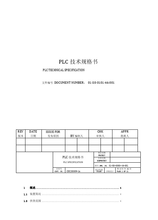
PLC技术规格书PLC TECHNICAL SPECIFICATION文件编号DOCUMENT NUMBER:01-50-0101-46-0011概述 (4)1.1装置简况 (4)1.5标准规范 (6)PLC规模数据61.6输入/输出信号类型 (6)1.7输入/输出信号规模 (7)1.8PLC系统配置图(建议) (8)系统功能要求81.9控制功能 (8)1.10画面功能 (9)1.11报表功能 (11)1.12历史数据存储功能 (11)系统配置要求111.13配置原则 (11)1.14操作站 (12)1.15控制和数据处理系统 (13)1.16通讯系统 (14)系统技术规格151.17冗余要求 (15)1.18平均无故障时间及平均故障修复时间 (16)1.19PLC的自诊断及容错 (16)1.20过程硬件接口要求(I/O) (16)1.21工作环境要求 (17)1.22电源系统 (17)1.23接地要求 (17)1.24控制室接地端子柜 (17)2技术资料交付 (17)3项目实施 (19)3.1项目进度 (19)3.2项目管理 (19)3.3设计协调 (19)3.4用户培训 (19)3.5现场服务 (20)4检查和验收 (20)4.1工厂验收 (20)4.2现场验收 (21)4.3其他检查 (21)5备品备件 (21)10质量保证与维修支持 (22)1概述1.1装置简况本套可编程逻辑控制器系统(PLC)用于凯米拉天成兖州AKD脱甲苯改造项目的生产过程控制、显示和I/O传输功能。
该装置安装一套年处理量8000吨的预处理装置将现有生产线生产的AKD 中甲苯含量从2000-15000ppm减低至1000ppm以下;并进入刮膜蒸发器系统继续处理至10ppm以下。
本工艺装置的危险区域分类为CLASS II,GROUP B,DIVITION 2。
本套PLC系统置于配备空调系统的操作室和机柜室内(非防爆区),其运行环境条件为:温度:夏天24—28℃,冬天16—20℃。
BC846系列NPN通用晶体管说明书

BC846 series65 V, 100 mA NPN general-purpose transistorsRev. 9 — 25 September 2012Product data sheet 1.Product profile1.1General descriptionNPN general-purpose transistors in Surface-Mounted Device(SMD) plastic packages.Table 1.Product overviewType number[1]Package PNP complementN experia JEITA JEDECBC846SOT23-TO-236AB BC856BC846W SOT323SC-70-BC856WBC846T SOT416SC-75-BC856T[1]Valid for all available selection groups.1.2Features and benefits⏹General-purpose transistors⏹SMD plastic packages⏹Two different gain selections1.3Applications⏹General-purpose switching and amplification1.4Quick reference dataTable 2.Quick reference dataSymbol Parameter Conditions Min Typ Max UnitV CEO collector-emitter voltage open base--65VI C collector current--100mAh FE DC current gain V CE=5V; I C=2mA110-450h FE group A110180220h FE group B2002904502.Pinning information3.Ordering information[1]Valid for all available selection groups.4.Marking[1]* = placeholder for manufacturing site codeTable 3.PinningPin Description Simplified outline Graphic symbolSOT23, SOT323, SOT4161base 2emitter 3collector006aaa144123sym02131Table 4.Ordering informationType number [1]Package NameDescriptionVersion BC846-plastic surface-mounted package; 3leads SOT23BC846W SC-70plastic surface-mounted package; 3leads SOT323BC846TSC-75plastic surface-mounted package; 3leadsSOT416Table 5.Marking codesType numberMarking code [1]BC8461D*BC846A 1A*BC846B 1B*BC846W 1D*BC846AW 1A*BC846BW 1B*BC846T 1M BC846AT 1A BC846BT1B5.Limiting values[1]Device mounted on an FR4Printed-Circuit Board (PCB), single-sided copper, tin-plated and standard footprint.6.Thermal characteristics[1]Device mounted on an FR4PCB, single-sided copper, tin-plated and standard footprint.Table 6.Limiting valuesIn accordance with the Absolute Maximum Rating System (IEC 60134).Symbol ParameterConditions Min Max Unit V CBO collector-base voltage open emitter -80V V CEO collector-emitter voltage open base -65V V EBO emitter-base voltage open collector -6V I C collector current -100mA I CM peak collector current single pulse; t p ≤1ms -200mA I BM peak base current single pulse; t p ≤1ms -200mAP tottotal power dissipation T amb ≤25︒C[1]SOT23-250mW SOT323-200mW SOT416-150mW T j junction temperature -150︒C T amb ambient temperature -65+150︒C T stgstorage temperature-65+150︒CTable 7.Thermal characteristics Symbol ParameterConditions Min Typ Max UnitR th(j-a)thermal resistance fromjunction to ambient in free air[1]SOT23--500K/W SOT323--625K/W SOT416--833K/W7.Characteristics[1]Pulse test: t p ≤300μs; δ=0.02.[2]V BEsat decreases by approximately 1.7mV/K with increasing temperature.[3]V BE decreases by approximately 2mV/K with increasing temperature.Table 8.CharacteristicsT amb =25︒C unless otherwise specified.Symbol ParameterConditions Min Typ Max Unit I CBOcollector-base cut-off currentV CB =30V;I E =0A --15nA V CB =30V;I E =0A; T j =150︒C --5μA I EBO emitter-base cut-off current V EB =5V; I C =0A --100nAh FEDC current gain V CE =5V; I C =10μAh FE group A -180-h FE group B -290-DC current gain V CE =5V; I C =2mA110-450h FE group A 110180220h FE group B200290450V CEsat collector-emitter saturation voltage I C =10mA;I B =0.5mA -90200mV I C =100mA; I B =5mA [1]-200400mV V BEsat base-emittersaturation voltage I C =10mA;I B =0.5mA [2]-760-mV I C =100mA; I B =5mA [2]-900-mV V BE base-emitter voltage I C =2mA; V CE =5V [3]580660700mV I C =10mA;V CE =5V [3]--770mV f T transition frequency V CE =5V; I C =10mA; f =100MHz100--MHz C c collector capacitance V CB =10V;I E =i e =0A; f =1MHz-23pF C e emitter capacitance V EB =0.5V; I C =i c =0A; f =1MHz-11-pF NFnoise figureI C =200μA; V CE =5V; R S =2k Ω; f =1kHz; B =200Hz-210dB8.Package outline9.Packing information[1]For further information and the availability of packing methods, see Section 13.[2]Valid for all available selection groups.Table 9.Packing methodsThe indicated -xxx are the last three digits of the 12NC ordering code.[1]Typenumber [2]Package DescriptionPacking quantity 100030004000BC846SOT234mm pitch, 8mm tape and reel -215--235BC846W SOT3234mm pitch, 8mm tape and reel -115--135BC846TSOT4164mm pitch, 8mm tape and reel-115--13510.Soldering11.Revision historyTable 10.Revision historyDocument ID Release date Data sheet status Change notice SupersedesBC846_SER v.920120925Product data sheet-BC846_SER v.8 Modifications:•Table 6 “Limiting values”: P tot values correctedBC846_SER v.820120424Product data sheet BC846_BC546_SER v.7 BC846_BC546_SER v.720091117Product data sheet-BC846_BC546_SER v.6 BC846_BC546_SER v.620060207Product data sheet--12.Legal information12.1 Data sheet status[1]Please consult the most recently issued document before initiating or completing a design.[2]The term ‘short data sheet’ is explained in section “Definitions”.[3]The product status of device(s) described in this document may have changed since this document was published and may differ in case of multiple devices. The latest product statusinformation is available on the Internet at URL .12.2 DefinitionsDraft — The document is a draft version only. The content is still under internal review and subject to formal approval, which may result in modifications or additions. Nexperia does not give anyrepresentations or warranties as to the accuracy or completeness of information included herein and shall have no liability for the consequences of use of such information.Short data sheet — A short data sheet is an extract from a full data sheet with the same product type number(s) and title. A short data sheet is intended for quick reference only and should not be relied upon to contain detailed and full information. For detailed and full information see the relevant full data sheet, which is available on request via the local Nexperia salesoffice. In case of any inconsistency or conflict with the short data sheet, the full data sheet shall prevail.Product specification — The information and data provided in a Product data sheet shall define the specification of the product as agreed between Nexperia and its customer, unless Nexperia andcustomer have explicitly agreed otherwise in writing. In no event however, shall an agreement be valid in which the Nexperia product isdeemed to offer functions and qualities beyond those described in the Product data sheet.12.3 DisclaimersLimited warranty and liability — Information in this document is believed to be accurate and reliable. However, Nexperia does not give any representations or warranties, expressed or implied, as to the accuracy or completeness of such information and shall have no liability for the consequences of use of such information. Nexperia takes noresponsibility for the content in this document if provided by an information source outside of Nexperia.In no event shall Nexperia be liable for any indirect, incidental,punitive, special or consequential damages (including - without limitation - lost profits, lost savings, business interruption, costs related to the removal or replacement of any products or rework charges) whether or not such damages are based on tort (including negligence), warranty, breach of contract or any other legal theory.Notwithstanding any damages that customer might incur for any reason whatsoever, Nexperia’s aggregate and cumulative liability towards customer for the products described herein shall be limited in accordance with the Terms and conditions of commercial sale of Nexperia.Right to make changes — Nexperia reserves the right to makechanges to information published in this document, including without limitation specifications and product descriptions, at any time and without notice. This document supersedes and replaces all information supplied prior to the publication hereof.Suitability for use — Nexperia products are not designed,authorized or warranted to be suitable for use in life support, life-critical or safety-critical systems or equipment, nor in applications where failure or malfunction of a Nexperia product can reasonably be expectedto result in personal injury, death or severe property or environmental damage. Nexperia and its suppliers accept no liability forinclusion and/or use of Nexperia products in such equipment or applications and therefore such inclusion and/or use is at the customer’s own risk.Applications — Applications that are described herein for any of these products are for illustrative purposes only. Nexperia makes no representation or warranty that such applications will be suitable for the specified use without further testing or modification.Customers are responsible for the design and operation of their applications and products using Nexperia products, and Nexperiaaccepts no liability for any assistance with applications or customer product design. It is customer’s sole responsibility to determine whether the Nexperia product is suitable and fit for the customer’s applications andproducts planned, as well as for the planned application and use of customer’s third party customer(s). Customers should provide appropriate design and operating safeguards to minimize the risks associated with their applications and products.Nexperia does not accept any liability related to any default,damage, costs or problem which is based on any weakness or default in the customer’s applications or products, or the application or use by customer’s third party customer(s). Customer is responsible for doing all necessary testing for the customer’s applications and products using Nexperia products in order to avoid a default of the applications andthe products or of the application or use by customer’s third partycustomer(s). Nexperia does not accept any liability in this respect.Limiting values — Stress above one or more limiting values (as defined in the Absolute Maximum Ratings System of IEC60134) will cause permanent damage to the device. Limiting values are stress ratings only and (proper) operation of the device at these or any other conditions above those given in the Recommended operating conditions section (if present) or the Characteristics sections of this document is not warranted. Constant or repeated exposure to limiting values will permanently and irreversibly affect the quality and reliability of the device.Terms and conditions of commercial sale — Nexperiaproducts are sold subject to the general terms and conditions of commercial sale, as published at /profile/terms, unless otherwise agreed in a valid written individual agreement. In case an individual agreement is concluded only the terms and conditions of the respective agreement shall apply. Nexperia hereby expressly objects toapplying the customer’s general terms and conditions with regard to the purchase of Nexperia products by customer.No offer to sell or license — Nothing in this document may be interpreted or construed as an offer to sell products that is open for acceptance or the grant, conveyance or implication of any license under any copyrights, patents or other industrial or intellectual property rights.Document status[1][2]Product status[3]DefinitionObjective [short] data sheet Development This document contains data from the objective specification for product development. Preliminary [short] data sheet Qualification This document contains data from the preliminary specification.Product [short] data sheet Production This document contains the product specification.Export control — This document as well as the item(s) described herein may be subject to export control regulations. Export might require a prior authorization from competent authorities.Quick reference data — The Quick reference data is an extract of the product data given in the Limiting values and Characteristics sections of this document, and as such is not complete, exhaustive or legally binding.Non-automotive qualified products — Unless this data sheet expressly states that this specific Nexperia product is automotive qualified,the product is not suitable for automotive use. It is neither qualified nor tested in accordance with automotive testing or application requirements. Nexperia accepts no liability for inclusion and/or use ofnon-automotive qualified products in automotive equipment or applications.In the event that customer uses the product for design-in and use in automotive applications to automotive specifications and standards, customer (a) shall use the product without Nexperia’s warranty of theproduct for such automotive applications, use and specifications, and (b) whenever customer uses the product for automotive applications beyond Nexperia’s specifications such use shall be solely at customer’sown risk, and (c) customer fully indemnifies Nexperia for anyliability, damages or failed product claims resulting from customer design and use of the product for automotive applications beyond Nexperia’sstandard warranty and Nexperia’s product specifications.12.4 TrademarksNotice: All referenced brands, product names, service names and trademarks are the property of their respective owners.13.Contact informationFor more information, please visit: For sales office addresses, please send an email to: salesaddresses@14. Contents1 Product profile. . . . . . . . . . . . . . . . . . . . . . . . . . 11.1 General description . . . . . . . . . . . . . . . . . . . . . 11.2 Features and benefits. . . . . . . . . . . . . . . . . . . . 11.3 Applications . . . . . . . . . . . . . . . . . . . . . . . . . . . 11.4 Quick reference data . . . . . . . . . . . . . . . . . . . . 12 Pinning information. . . . . . . . . . . . . . . . . . . . . . 23 Ordering information. . . . . . . . . . . . . . . . . . . . . 24 Marking. . . . . . . . . . . . . . . . . . . . . . . . . . . . . . . . 25 Limiting values. . . . . . . . . . . . . . . . . . . . . . . . . . 36 Thermal characteristics . . . . . . . . . . . . . . . . . . 37 Characteristics. . . . . . . . . . . . . . . . . . . . . . . . . . 48 Package outline . . . . . . . . . . . . . . . . . . . . . . . . . 79 Packing information . . . . . . . . . . . . . . . . . . . . . 810 Soldering . . . . . . . . . . . . . . . . . . . . . . . . . . . . . . 911 Revision history. . . . . . . . . . . . . . . . . . . . . . . . 1212 Legal information. . . . . . . . . . . . . . . . . . . . . . . 1312.1 Data sheet status . . . . . . . . . . . . . . . . . . . . . . 1312.2 Definitions. . . . . . . . . . . . . . . . . . . . . . . . . . . . 1312.3 Disclaimers. . . . . . . . . . . . . . . . . . . . . . . . . . . 1312.4 Trademarks. . . . . . . . . . . . . . . . . . . . . . . . . . . 1413 Contact information. . . . . . . . . . . . . . . . . . . . . 1414 Contents . . . . . . . . . . . . . . . . . . . . . . . . . . . . . . 15© Nexperia B.V. 2017. All rights reserved For more information, please visit: Forsalesofficeaddresses,pleasesendanemailto:*************************** Date of release:Mouser ElectronicsAuthorized DistributorClick to View Pricing, Inventory, Delivery & Lifecycle Information:N experia:BC846BW,135BC846B,235BC846A,215BC846,215BC846W,135BC846AW,135BC846AT,115BC846BW,115 BC846T,115BC846A,235BC846W,115BC846BT,115BC846B,215BC846AW,115。
Datasheet MLX90614 中文 数据手册 rev008
10-位 PWM 输出模式是连续输出所测物体温度的标准配置,测量物体的温度范围为-20…120 °C,分辨 率为 0.14 °C。PWM 通过修改 EEPROM 内 2 个单元的值,实际上可以根据需求调整至任何温度范围,而这对 出厂校准结果并无影响。
传感器的测量结果均出厂校准化,数据接口为数字式的 PWM 和 SMBus(System Management Bus) 输出。
作为标准,PWM 为 10 位,且配置为-20˚C 至 120 ˚C 内,分辨率为 0.14 ˚C 的连续输出。
传感器出厂默认,上电复位时为 SMBus 通信。
3901090614 Rev 008
PWM 引脚也可配置为热继电器(输入是 To),这样可以实现简单且性价比高的恒温控制器或温度报警(冰 点/沸点)应用,其中的温度临界值是用户可编程的。在 SMBus 系统里,这个功能可以作为处理器的中断信号, 以此触发读取主线上从动器的值,并确定精度条件。
传感器有两种供电电压选择:5V 或 3V(电池供电)。其中,5V 也可简便的从更高供电电压(例如 8 至 16V)上通过外接元件调制。(具体请参考“应用信息”)
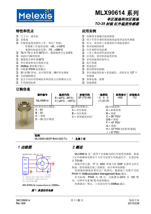
MLX90614 connection to SMBus
图 1: 典型应用电路
2 概述
MLX90614 是一款用于非接触式的红外温度传感器,集成 了红外探测热电堆芯片与信号处理专用集成芯片,全部封装 在 TO-39。
低噪声放大器、17 位 ADC 和强大的 DSP 处理单元的全 集成,使传感器实现了高精度,高分辨率的测量。
安全仪表系统(SIS)技术规格书
安全仪表系统(SIS)技术规格书目录1 总则 (4)1.1 概述 (4)1.2 工厂及装置简况 (4)1.3 卖方的责任 (4)1.4 供货及服务范围 (4)1.5 报价技术文件要求 (4)1.6 无效报价 (6)1.7 关于招标及投标的修改 (6)1.8 本规格书程度用词 (6)2 系统技术规格 (7)2.1 概述 (7)2.2 技术要求 (7)2.3 通信要求 (15)2.4 系统负荷要求 (16)2.5 维护和安全、可靠性要求 (17)2.6 系统机柜 (18)2.7 辅助机柜 (18)2.8 电缆及连接配件 (19)2.9 电源及接地 (19)3 软件配置的基本要求 (20)3.2 软件的版本更新 (20)3.3 汉字系统 (20)4 备品备件及辅助工具 (20)4.1 备品备件 (20)4.2 专用仪器和工具 (20)5 文件资料 (20)5.1 工程设计文件资料 (20)5.2 应用手册文件 (21)5.3 中间文件资料 (21)5.4 组态培训资料 (21)5.5 文件资料的文字 (21)6 技术服务 (22)6.1 概述 (22)6.2 项目管理 (22)6.3 工程条件会 (22)6.4 现场技术服务 (22)6.5 操作运行服务 (23)7 技术培训及软件组态 (24)7.1 系统技术培训 (24)7.2 软件组态培训 (24)7.3 组态 (24)7.5 操作培训 (24)8 测试与验收 (25)8.1 工厂测试与出厂验收 (25)8.2 现场验收 (25)9 性能保证 (25)9.1 性能保证 (25)9.2 备件 (26)10 特殊要求 (26)附图1. 中心控制室建筑平面图 (26)附录1. 系统硬件清单及技术服务 (27)附录2. 检测点统计表 (30)1 总则1.1 概述本安全仪表系统(以下简称SIS)规格书为××××××××××公司××××××工程而编制。
- 1、下载文档前请自行甄别文档内容的完整性,平台不提供额外的编辑、内容补充、找答案等附加服务。
- 2、"仅部分预览"的文档,不可在线预览部分如存在完整性等问题,可反馈申请退款(可完整预览的文档不适用该条件!)。
- 3、如文档侵犯您的权益,请联系客服反馈,我们会尽快为您处理(人工客服工作时间:9:00-18:30)。
下游侧 5D 以上 (D 为管内径 )
详情参见日本工业标准 JEMS-032
测量对象
・ 被 测 流 体: 超声波可透过的均质液体 ・ 流 体 浊 度: 10,000 度 (mg /L) 以下 ・ 流 体 状 态: 充满圆管内的充分形成的紊流或层流 ・ 流 体 温 度: -40~+200°C ・ 测 量 范 围: 0……±0.3~±32m/s
Ϗކ
CDS6–147b
发行日 2013 – 04 – 10
FSC-2、FSS、FSD
性能规格
・ 额定精度:
管内径 f13~f50mm f50~f300mm f300~f6000mm
流速范围 2~32m/s 0~2m/s 2~32m/s 0~2m/s 1~32m/s 0~1m/s
精度 ±1.5% of rate ±0.03m/s ±1.0%~1.5% of rate ±0.02~0.03m/s ±1.0%~1.5% of rate ±0.01~0.02m/s
温 (20°C) 的状态下 )
充电时间 3 小时 ( 使用专用电源适配器 )
充电温度范围 0~+40°C
功
耗 最小:3W、最大:16W
随使用条件的改变而变化
电 源 适 配 器 专用电源适配器 AC90V~264V
(50/60Hz),70VA 以下
・ 液 晶 显 示: 半透光型彩色图形显示器
240×320 点阵 ( 带背光 )
( 注 ) 选择汉语显示时,打印的文字是日
文汉字
・ 环 境 温 度: -10~+55°C( 无打印机 )
-10~+45°C( 带打印机 )
・ 环 境 湿 度: 90%RH 以下
・ 外 壳 类 型: IP64( 无打印机时 )
・外
壳: 塑料壳
・ 外 形 尺 寸: H210×W120×D65mm( 无打印机 )
FSSD
V͖2͕ Z͖1͕
e1.5 Ϊ2.5
e1.0 e1.0
FSSC FSSE FSSH
V Z V Z V Z͖1͕
e1.5
e1.0 e1.0
e1.0 e1.0
e1.5 e1.5
e1.0 e1.0
※1) FSSD和FSSH以Z法安装使用时,需要另外购买导轨(选配件)。 ※2) 安装配管内径为f13mm时,根据配管材质和厚度,检测器的安装尺寸有时在0.0mm以下。
特点
1. 小型轻量 采用最新的电子技术和数字信号处理技术,和本公司以往 产品相比变换器的体积仅为原来的 30%,重量减轻了 30%。
2. 电池工作方式 靠内置电池可以连续工作 12 小时。 电池为快速充电式,使用附带的电源适配器 3 个小时即可 充满。
3. 传感器种类齐全 能够满足小口径到大口径 ( 管内径 f13~f6000mm)、 低温流体到高温流体 (-40~+200°C) 等多种要求。
( 注 1) 基准工作条件:以日本工业标准 JEMIS-032 为依据。 ( 注 2) 精度详细内容请参照第四页。
变换器 ( 型号:FSC)
・电
源: 内置电池或 AC 电源适配器
内 置 电 池 专用锂离子电池 (5000mAh)
连续工作时间 12 小时 ( 在无打印机、背
光关闭、不使用电流输出、环境温度为常
・ 瞬时值显示功能: 可显示瞬时流速、瞬时流量 ( 反向流动以 负值显示 ) 数字:10 位 ( 小数点占 1 位 ) 单位有公制 / 英制两种,可供选择 公制单位 流速:m/s 流量:L/s、L/min、L/h、L/d、kL/d、 ML/d、m3/s、m3/min、m3/h、 m3/d、km3/d、Mm3/d、其它
FRP 管、铜管、铝管、丙烯管
或已知声速的材质
・ 适 用 管 道 口 径:流量测量
f13~f6000mm
流速分布测量 f40~f1,000mm
・ 衬 垫 材 质:无、沥青环氧、砂浆、橡胶、聚四氟乙烯、
硼硅酸玻璃,或已知声速的材质
( 注 ) 衬垫应与管道无间隙,紧密接触
・ 最小直管段长度: 上游侧 10D 以上
便携式超声波流量计 (PORTAFLOW—C)
PORTABLE TYPE ULTRASONIC FLOWMETER (PORTAFLOW-C)
选型资料
FSC-2、FSS、FSD
PORTAFLOW-C 为便携式超声波流量计,采用传播时间差法, 可以从管道外部测量管内的体积流量。 采用最新的电子技术和数字信号处理技术,使产品在小型轻量 化上实现了质的飞跃,同时功能和操作性也大大提高。
༶ݠ (߄ͦغFSS)
T2ͦ᧽ݸҗሂ၏Цᤇྖਇ
Qͦ၏Цᤇ༯
・ 温 度 显 示 功 能:通过来自温度变换器的输入电流显示流体
温度
温度:°C、K
・ 地 址 登 录 功 能:本体的非易失性存储器最多可登录 32 个地
址信息 ( 管道数据等 )
・阻
尼:相对于模拟量输出以及流速 / 流量显示,
△
(ON,OFF,ENT,ESC,MENU,△, ,
△
△
, ,LIGHT,PRINT)
进行各种设定
・ 断 电恢 复处 理: 由非易失性存储器进行设定值备份
由锂电池为时钟供电 ( 有效期:10 年以上 )
・ 响 应 速 度: 1 秒
・ 模拟量输出信号:
DC4~20mA,1 点 ( 负载电阻 600Ω 以下 )
为 0~100 秒 ( 步长 0.1 秒 ) 缓冲
・ 低 流 量 截 断:相当于 0~5m/s
・ 输 出 设 定 功 能 :可进行电流输出的比例缩放、输出形式、
中断的设定以及校正
・ 串 行 通 信 功 能:可通过计算机处理瞬时流量、瞬时流速、
累计值、热流量
出错信息、接收信号、模拟量输入、流速
分布数据、记录数据等项目
其它:BNC 连接器
・ 环 境 温 度:-20~+60°C
・ 环 境 湿 度:FSSE 100%RH 以下
其它
90%RH 以下
・ 外 壳 类 型:FSSC IP65( 防水连接器嵌合时 )
FSSE IP67
其它
IP52
・ 检测器的材质:
种类
型号
检测部 外壳材质
安装带 / 金属丝
中型检测器 FSSC 塑料
-40~120°C
f13~f300
-40~100°C
f200~f6000
-40~80°C
f50~f400
-40~200°C
・ 设 置 方 法:安装在管道的外侧
・ 传感器安装方法:V 法或 Z 法
・ 信 号 线:专用同轴电缆 5m(FSC 主机附带 ) ・ 连 接 方 法:变换器侧 专用连接器
检测器侧 FSSE:压接端子
输出经比例缩放的瞬时流量、瞬时流速或
热量
・ 模拟量输入信号:
DC4~20mA,
1 点 ( 输入电阻 200Ω) DC4~20mA,
合计2点
( 输入电阻 200Ω)
或 DC1~5V,1 点
用于热量测量的温度输入等
・ S D 存 储 卡: 数据记录功能,用于记录画面数据
最大可用容量 8GB
( 选配件:256MB)
4. 高准确度、高速响应 准确度极高,准确度为 ±1.0%。 响应速度小于 1 秒。
5. 抗气泡能力提高 采用数字信号处理,抗气泡能力已大大提高。
6. 优异的操作性和使用便利性 即使在室外也容易分辨的大型彩色液晶显示,按键少,菜 单选择方式,设定简单。 防水保护结构 ( 仅限内置电池驱动时 ),雨中也可使用。
铝合金 + 塑料
小型检测器 FSSD 塑料
铝合金 + 塑料
大型检测器 FSSE 塑料
––
高温检测器 FSSH SUS304
铝合金 +SUS304
・ 安装带的尺寸,材质:
检测器型号 第6位
尺寸
A
1.5m (2 根 )
材质 SUS304
B
3.0m (1 根 )
塑料布带
C
1.0m (4 根 )
SUS304
H320×W120×D65mm( 带打印机 )
・重
量: 1.0kg( 无打印机 )
1.2kg( 带打印机 )
各种功能
・ 显 示 语 言: 可选择日语、英语、德语、法语、西班牙语、 汉语 ( 通过键盘操作切换 )
・ 时 钟 显 示 功 能: 可显示和设定时刻 ( 年、月、日、时、分 ) 精度 每月约差 1 分钟 at 常温 (20°C)
9. 热量测量 可通过温度输入进行热量测量。可简单进行制冷制热的能 量管理。
10.图形打印机连接 ( 选配件 ) 采用一体式打印机,记录方便
11. 流速分布显示 ( 选配件 ) 可实时观测液流的状态。
规格
变换器 (FSC)
伸缩轨道型检测器 ( 型号:FSSC)
高温检测器 (FSSH)
管道条件
・ 适 用 管 道 材 质:钢管、不锈钢管、铸铁管、聚氯乙烯管、
7. SD 存储卡记录容量大 能以固定的周期将测量数据保存到 SD 存储卡中。例如, 选配件的 256MB 存储卡可保存约 1 年的测量数据 ( 保存周 期为 30 秒,保存数据 14 种时 ),最大可用容量为 8GB。
8. 串行通信 采用 USB 端口,与计算机的连接非常容易。 备有计算机用装载软件 ( 标准 ),可进行测量数据的收集和 参数 ( 地址设定 ) 的显示、变更。
・ 流速分布显示功能 ( 选配 ):
可使用专用检测器 ( 选配件 ) 实时观测流
速分布
( 详情参见第 5 页 )
检测器 ( 型号:FSS)