BuW-Demontage-SV-UV
路由器无线N300 WNR2000v4 安装指南说明书
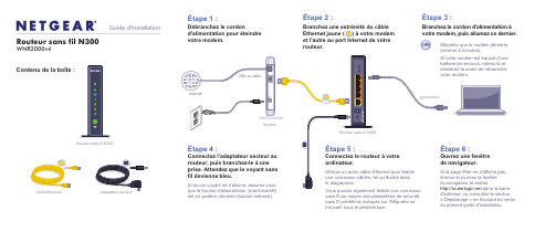
votre modem, puis allumez ce dernier.Contenu de la boîte :Routeur sans fil N300WNR2000v4Guide d'installationCâble EthernetRouteur sans fil N300(non fourni)est en position allumée (bouton enfoncé).sans fil au moyen des paramètres de sécurité sans fil prédéfinis indiqués sur l'étiquette se trouvant sous le périphérique.d'adresse, ou consultez la section « Dépannage » se trouvant au verso du présent guide d'installation.Attendez que le modem démarre (environ 2 minutes).Si votre modem est équipé d'une batterie de secours, retirez-la et réinsérez-la avant de rebrancher votre modem.NETGEAR, le logo NETGEAR et Connect with Innovation sont des marques de commerce ou des marques déposées de NETGEAR, Inc. ou de ses sociétés affiliées aux États-Unis et dans d'autres pays. Ces informations sont susceptibles d'être modifiées sans préavis. Les autres marques ou noms de produits sont des marques déposées de leurs détenteurs respectifs. © NETGEAR, Inc. Tous droits réservés.Uniquement pour utilisation intérieure dans les pays membres de l'UE, les pays membres de l'AELE et en Suisse.Novembre 2012Pour la déclaration de conformité complète pour l'UE, consultez le /app/answers/detail/a_id/11621/Repérez les paramètres sans fil prédéfinis sur votre routeur et Connexion des périphériques sans fil à votre routeurChoisissez la méthode manuelle ou WPS (Wi-Fi Protected Setup) pour ajouter des ordinateurs ou autres périphériques à votre réseau sans fil.Méthode manuellencez l'utilitaire qui gère vos connexions sans fil sur le périphérique sans fil(iPhone, ordinateur portatif ou de bureau, console de jeux) que vous voulez connecter à votre routeur. Cet utilitaire recherche tous les réseaux sans fil de votre secteur.2.Recherchez le nom du réseau sans fil NETGEAR prédéfini (SSID) etsélectionnez-le. Ce nom est indiqué sur l'étiquette du produit, située sous le routeur.Remarque : Si vous avez modifié le nom de votre réseau pendant le processus de configuration, recherchez-le.3.Entrez le mot de passe prédéfini (ou votre mot de passe personnalisé si vousl'avez modifié), puis cliquez sur Connect (Connexion).4.Répétez les étapes 1 à 3 pour ajouter d'autres périphériques sans fil.Méthode WPSSi votre périphérique sans fil prend en charge la fonctionnalité WPS (Wi-Fi Protected Setup), que NETGEAR appelle la méthode « Appuyez : vous êtesconnecté », il vous sera peut-être demandé d'appuyer sur le bouton WPS situé sur le routeur au lieu d'entrer un mot de passe. Le cas échéant :1.Appuyez sur le bouton WPSdu routeur.2.Dans un délai de deux minutes, appuyez sur le bouton WPS sur lepériphérique client ou suivez les instructions de l'utilitaire WPS incluses avec votre appareil sans fil. Le périphérique sera alors connecté à votre routeur. 3.Répétez cette procédure pour ajouter d'autres périphériques sans fil WPS.Remarque : La fonction WPS ne prend pas en charge la sécurité WEP. Si vous essayez de connecter un client WEP à votre réseau au moyen de la fonction WPS, la connexion échouera.DépannageLe navigateur ne peut afficher la page Web.• Assurez-vous que votre ordinateur est connecté en réseau local à l'un desquatre ports Ethernet ou qu'il est connecté via connexion sans fil au routeur.• Assurez-vous que le routeur est correctement alimenté en électricité et que levoyant de réseau sans fil est devienne bleu.• Fermez et rouvrez la fenêtre pour vous assurer que le navigateur n'a pas misen cache la page précédente.• Allez à l'adresse .• Si l'ordinateur est configuré de manière à utiliser une adresse IP statique ou fixe(ce qui est rare), modifiez le paramètre pour obtenir automatiquement une adresse IP du routeur.Après l'installation de votre appareil, notez le numéro de série inscrit sur l'étiquette située sous votre produit. Il vous sera nécessaire pour enregistrer votre produit à l'adresse https:// . Vous devez enregistrer votre produit avant de pouvoir bénéficier des services de soutien par téléphone NETGEAR. NETGEAR vous recommande d'enregistrer votre produit via le site Web NETGEAR. Pour obtenir des mises à jour de produits et consulter le support Web, visitez le site .Si vous désirez obtenir le logiciel gratuit de filtrage centralisé de sites Web Live Parental Controls pour votre routeur, vous pouvez le télécharger à l'adresse /lpc .Pour toute autre fonctionnalité, y compris le compteur de trafic et l'accès réservé aux invités, ouvrez une session sur votre routeur à l'adresse .Vous pouvez obtenir le manuel de l'utilisateur en ligne au ou via un lien dans l'interface utilisateur du produit.NETGEAR vous recommande d'utiliser uniquement les ressources d'assistance officielles NETGEAR.Téléchargez gratuitement NETGEAR Genie Corrigez automatiquement les problèmes de réseau les plus courants et gérez facilement vos connexions de réseautage à domicile./genie。
Ubuntu下5大图像查看软件-电脑资料
Ubuntu下5大图像查看软件-电脑资料
Gwenview
是较好的一项应用,支持几乎所有图片格式,可进行基本的编辑、标签、缩略图、全屏、幻灯显示功能等等,。
安装
sudo apt-get install gwenview
Eye of GNOME
是GNOME环境下较好的图片查看器,支持JPG, PNG, BMP, GIF, SVG, TGA, TIFF or XPM等图片格式,也可放大、幻灯显示图片、全屏、缩略图等功能。
安装
sudo apt-get install eog
gThumb
是另一GTK图片查看器,可导入Picasa或Flickr图片,也可导出到 Facebook, Flickr, Photobucker, Picasa 和本地文件夹,电脑资料
《Ubuntu下5大图像查看软件》(https://)。
安装
sudo apt-get install gthumb
Viewnior
是小型化的图片查看器,支持JPG和PNG格式。
安装
sudo apt-get install viewnior
gPicView
是LXDE下的默认图片查看器,操作按钮位于窗口底部。
只需右击图片,实现所有相关功能。
支持JPG, TIFF, BMP, PNG , ICO格式。
安装
sudo apt-get install gpicview。
WiFi Extender 用户手册说明书
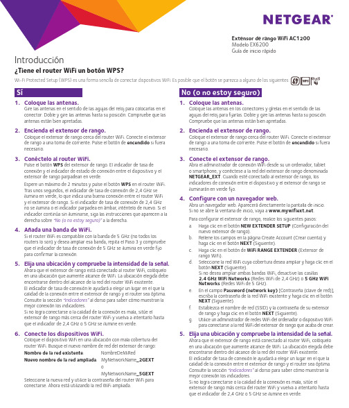
1. Coloque las antenas.Gire las antenas en el sentido de las agujas del reloj para colocarlas en el conector. Doble y gire las antenas hasta su posición. Compruebe que las antenas están bien apretadas.2. Encienda el extensor de rango.Coloque el extensor de rango cerca del router WiFi. Conecte el extensor de rango a una toma de corriente. Pulse el botón de encendido si fuera necesario.3. Conéctelo al router WiFi.Pulse el botón WPS del extensor de rango. El indicador de tasa deconexión y el indicador de estado de conexión entre el dispositivo y elextensor de rango parpadean en verde.Espere un máximo de 2 minutos y pulse el botón WPS en el router WiFi.Tras unos segundos, el indicador de tasa de conexión de 2,4 GHz seilumina en verde, lo que indica una buena conexión entre el router WiFi y el extensor de rango. Si el indicador de tasa de conexión de 2,4 GHzno se ilumina o el indicador parpadea en ámbar, inténtelo de nuevo. Si el indicador continúa sin iluminarse, siga las instrucciones que aparecen a la derecha sobre “No (o no estoy seguro)” a la derecha.4. Añada una banda de WiFi.Si el router WiFi es compatible con la banda de 5 GHz (no todos losrouters lo son) y desea ampliar esa banda, repita el Paso 3 y compruebe que el indicador de tasa de conexión de 5 GHz se ilumina en verde fijopara confirmar la conexión.5. Elija una ubicación y compruebe la intensidad de la señal.Ahora que el extensor de rango está conectado al router WiFi, colóquelo en una ubicación que aumente alcance de WiFi. La ubicación elegida debe encontrarse dentro del alcance de la red del router WiFi existente.El indicador de tasa de conexión le ayudará a elegir un lugar en el que la calidad de la conexión entre el extensor de rango y el router sea óptima.Consulte la sección “Indicadores” al dorso para saber cómo muestran la mejor conexión los indicadores.Si no logra conectarse o la calidad de la conexión es mala, sitúe elextensor de rango más cerca del router WiFi y vuelva a intentarlo hasta que el indicador de 2,4 GHz o 5 GHz se ilumine en verde.6. Conecte los dispositivos WiFi.Coloque el dispositivo WiFi en una ubicación con mala cobertura delrouter WiFi. Busque el nuevo nombre de red del extensor de rango:Nombre de la red existente. NombreDeMiRedNuevo nombre de la red ampliada. MyNetworkName_2GEXToMyNetworkName_5GEXTSeleccione la nueva red y utilice la contraseña del router WiFi paraconectarse. Ahora está utilizando la red WiFi ampliada.1. Coloque las antenas.Coloque las antenas en los conectores y gírelas en el sentido de lasagujas del reloj para fijarlas. Doble y gire las antenas hasta su posición.Compruebe que las antenas están bien apretadas.2. Encienda el extensor de rango.Coloque el extensor de rango cerca del router WiFi. Conecte el extensor de rango a una toma de corriente. Pulse el botón de encendido si fuera necesario.3. Conecte el extensor de rango.Abra el administrador de conexión WiFi desde su un ordenador, tableto smartphone, y conéctese a la red del extensor de rango denominadaNETGEAR_EXT. Cuando esté conectado al extensor de rango, losindicadores de conexión entre el dispositivo y el extensor de rango seiluminarán en verde fijo.4. Configure con un navegador web.Abra un navegador web. Aparecerá directamente la pantalla de inicio.Si no se abre la ventana de inicio, vaya a .Para configurar el extensor de rango, realice los siguientes pasos:a. Haga clic en el botón NEW EXTENDER SETUP (Configuración delnuevo extensor de rango).b. Rellene los campos en la página Create Account (Crear cuenta) yhaga clic en el botón NEXT (Siguiente).c. Haga clic en el botón de WiFi RANGE EXTENDER (Extensor derango WiFi).d. Seleccione la red WiFi cuya cobertura desea ampliar y haga clic en elbotón NEXT (Siguiente).Si no desea ampliar ambas bandas WiFi, desactive las casillas2.4 GHz WiFi Networks (Redes WiFi de 2,4 GHz) o 5 GHz WiFiNetworks (Redes WiFi de 5 GHz).e. En el campo Password (network key) [Contraseña (clave de red)],escriba la contraseña de la red WiFi existente y haga clic en el botónNEXT (Siguiente).f. Establezca el nombre de red (SSID) y la contraseña de su extensorde rango y haga clic en el botón NEXT (Siguiente).g. Utilice un administrador de redes WiFi del ordenador o dispositivo WiFipara conectarse a la red WiFi del extensor de rango que acaba de crear.5. Elija una ubicación y compruebe la intensidad de la señal.Ahora que el extensor de rango está conectado al router WiFi, colóquelo en una ubicación que aumente alcance de WiFi. La ubicación elegida debe encontrarse dentro del alcance de la red del router WiFi existente.El indicador de tasa de conexión le ayudará a elegir un lugar en el que la calidad de la conexión entre el extensor de rango y el router sea óptima.Consulte la sección “Indicadores”al dorso para saber cómo muestran la mejor conexión los indicadores.Si no logra conectarse o la calidad de la conexión es mala, sitúe elextensor de rango más cerca del router WiFi y vuelva a intentarlo hasta que el indicador de 2,4 GHz o 5 GHz se ilumine en verde.Modelo EX6200Guía de inicio rápidoIntroducción¿Tiene el router WiFi un botón WPS?SíNo (o no estoy seguro)Modelo EX6200Guía de inicio rápidoHardwarePanel frontal y lateralPanel posteriorDeberá registrar su producto para poder hacer uso de nuestro servicio telefónico de soporte técnico NETGEAR. NETGEAR recomienda registrar su producto a través del sitio web de NETGEAR.Podrá encontrar actualizaciones del producto y asistencia técnica en .Encontrará el manual del usuario online en o a través de un vínculo en la interfaz del GEAR le recomienda que utilice solo los recursos del soporte técnico oficial de NETGEAR.Para consultar la declaración de conformidad actual de la UE, visite: /app/answers/detail/a_id/11621/. Para obtener información sobre el cumplimiento de normativas, visite /about/regulatory/. Consulte el documento de cumplimiento normativo antes de conectar la fuente de alimentación.© NETGEAR, Inc., NETGEAR y el logotipo de NETGEAR son marcas comerciales registradas de NETGEAR, Inc. Cualquier marca comercial distinta a NETGEAR que se utilice, se usa únicamente a modo de GEAR, Inc. 350 East Plumeria Drive, San Jose, CA 95134 (EE. UU.)Julio de 2015。
montage参数

Montage是一个用于图像拼接的软件,其参数可以根据具体的使用场景和需求进行调整。
以下是一些常见的Montage参数及其作用:
输入文件名:指定要进行拼接的图像文件名。
可以指定多个文件,以便将它们组合在一起。
输出文件名:指定拼接后的图像的输出文件名。
图像大小:指定输出图像的大小。
可以通过输入宽度和高度值来调整输出图像的大小。
拼接方式:选择图像拼接的方式。
常见的拼接方式包括横向拼接、纵向拼接、自由拼接等。
图像间距:指定拼接图像之间的间距。
通过调整间距值,可以控制拼接后图像之间的空隙大小。
背景颜色:指定拼接后图像的背景颜色。
可以选择不同的颜色或使用透明背景。
重叠区域处理:指定如何处理重叠区域的图像。
可以选择不同的算法来调整重叠区域的亮度、对比度和颜色。
平滑处理:对拼接后的图像进行平滑处理,以减少拼接痕迹和失真。
可以选择不同的平滑算法和参数来控制平滑效果。
图像质量:调整输出图像的质量。
可以通过设置压缩率、分辨率等参数来控制输出图像的质量。
其他参数:根据具体的使用场景和需求,还可以调整其他参数,如旋转角度、缩放比例等。
请注意,以上参数只是Montage软件中一些常见的参数,实际使用时可能还有其他参数可供调整。
建议参考Montage的官方文档或软件帮助文档,以获取更详细的信息和指导。
伊斯姆兹(Isuzu)中型货车和拖车产品目录说明书

4HK1-TCC / -TCS 6HK1-TCN / -TCS910 Visibility and protection from every angleEnhanced brakingExtra-large front and rear drum brakes improve braking performanceand are carefully matched to meet the requirements of each model.Designed for easy maintenanceWhen there is a big job, FORWARD will be ready.The quick access front panel facilitates routine replenishment of clutchand washer fluids as well as brake valve maintenance.Cleaning the windshield is a snapA full-length bumper step and hand grips take the hard work out ofcleaning the windshield. The bumper step and grips also offer steadysupport for adjustment of mirrors. For remote adjustment from insidethe cab, power mirrors are available.Simplified fluid inspection and other service workChecking fluids is simple. An engine oil inspection port is located at theback of the cab, along with brake fluid and long-life coolant reservoirs.The relay box is also conveniently placed at the back of the cab forstraightforward inspection. Even fuse replacement inside the cab belowthe instrument panel is easy, thanks to a cartridge-type fuse box.Backing safety systemIn reverse gear, the backing safety system is triggered automatically;lamps flash and a buzzer sounds to warn pedestrians and other vehicles.Safe stopping and parking at all timesOptional exhaust braking guarantees safe stopping even when fully loaded,while the parking brake lever locks wheels firmly in place.Greater illumination from headlamps / fog lampsLarger headlamp bulbs provide better forward illumination during nighttime operation,while fog lamps increase the level of safety in bad weather.The exceptional visibility of highly rigid FORWARD cabs is due in part to their boxy design,which increases window area. Upward and downward forward visibility is first-rate,and large side mirrors give excellent rear views. Defrosters keep side windows clear.1112 3,700mm wheelbase (FSR model)Easy handling and precision controlTight turning radiusWith a maximum steering angle of 57 degrees and reduced front overhang,FORWARD can maneuver with precision in congested areas and tight quarters.Power steering / adjustable columnPower steering and tilt / telescopic column adjustment are standard,helping to reduce driver fatigue.Suspended brake pedalSuspending the brake pedal provides a more natural, car-like driving experience.It also allows the brake valve to be placed in the quick access area for easiermaintenance without tilting the cab.High-visibility meters, simple operationMeters are located in the center for superior visibility,allowing drivers to confirm vehicle status at a glance.Surrounding switches are designed for easy control.FORWARD takes handling and control to the next level.Chassis and drivetrain enhancements work together with easy-to-read indicators andswitches to give unmatched control over vehicle operations.Day in and day out, drivers will appreciate the flawless handling and easy operation.Crawler gear to move big loadsOn higher GVM models equipped with the ZF9S1110 transmission,a crawler gear provides the power to move heavy, oversize loads.Smooth and effortless shiftingRefinements to the master cylinder reduce the effort involved inmanual shifting and ensure a smooth ride.Reliability and durability are also enhanced.Inter differential lock /center differential lock /4WD switchesFor maximum drive-axle traction in extreme conditions, two separatedifferential locks are available along with a 4WD driving system.Just flip the dash-mounted switches when conditions call fora sure grip in slippery spots.70°1718 Line upGVM 10.4ton4x2 DRIVING SYSTEM6x2 DRIVING SYSTEM6x4 DRIVING SYSTEMFRR4x4 DRIVING SYSTEMGVM 25.0tonFVM GVM 25.0tonFVZGVM 13.0tonFTS4HK1-TCC, 4HK1-TCS, 6HK1-TCN, 6HH1-S4HK1-TCS6HK1-TCN, 6HK1-TCS6HK1-TCS4HK1-TCS, 6HK1-TCN, 6HH1-S6HK1-TCN, 6HH1-SGVM 11.0ton/13.0tonFSR4x4 DRIVING SYSTEMGVM 10.0tonFSS4x2 DRIVING SYSTEM*Disc wheel step is optionalBumper headlamps (FVR33 model)。
VX-1700 HF SSB移动无线电说明书

VX-1700HOJA DE ESPECIFICACIONES – AMÉRICA L ATINA Comunicaciones de largo alcanceEl radio VX-1700 multiuso está diseñado para operar como radio móvil o como estación base para comunicaciones móviles fijas de largo alcance. Los modos de operación incluyen LSB/USB (J3E y J2B), AM (A3E) y CW (A1A), convirtiendo al radio VX-1700 en la solución ideal para una amplia variedad de aplicaciones. Popular para el uso por parte de ciudades y gobiernos locales para apoyar la gestión de seguridad pública y respuesta a situaciones de desastre.Amplia capacidad de canalesEl radio VX-1700 puede almacenar hasta 200 canales dispuestos en cinco grupos con la flexibilidad necesaria para tener cualquier número de canales por grupo. Cada canal puede ser programado con una descripción alfanumérica de 6 caracteres para una gestión de llamadas rápida y fácil. Opción de establecimiento automático de enlaces (ALE) Con la opción ALE-1 instalada, el radio VX-1700 selecciona automática- mente el canal que tenga el mejor análisis de calidad de enlace (LQA) entre los canales programados.Opciones flexibles de llamadasIncluye 6 modos de llamada integrados para apoyar varios tipos de comunicaciones:L lamada selectiva (SELCALL): efectúe llamadas a un individuo o grupo usando el número de ID asignado para cada transceptor de llamada privadaL lamada de verificación de señal (Beacon Request Call): verifique la calidad de la señal entre transceptores antes de efectuar una llamada selectiva para cerciorarse de que la misma sea viableL lamada telefónica (TELCALL): efectúe una llamada a través del servicio de interconexión telefónica para expandir el contacto con individuos por teléfonoL lamada de mensajería: envíe mensajes de texto (hasta 64 caracteres) a otro transceptor para expandir las opciones de comunicaciónL lamada de solicitud de posición: monitoree la información de posición de otro transceptor cuando use una unidad móvilL lamada de envío de posición: transmita la información de posición a otro transceptor para notificar a otros usuarios su ubicación actual Operación de vigilancia doblePermite operar el radio VX-1700 en un canal mientras se vigila periódicamente el canal designado en la memoria para cerciorarse de que no se pierda ninguna llamada. Es ideal para situaciones de coordinación de emergencias cuando es imprescindible que una llamada llegue al despachador.VX-1700La diferencia Vertex Standard Nuestro principal objetivo es alcanzar un máximo nivel de satisfacción del cliente ofreciendo productos y servicios que excedan sus expectativas. Los radios Vertex Standard son diseñados para durar y son fabricados con total precisión para ofrecer el máximo valor posible y un desempeño óptimo proporcionando una conexión sin riesgos.Otras funciones4 teclas programables Silenciador de ruido Semi-interrupción CWFunción de tono lateral CWFunciones de Bloqueo de Canal Ocupado (BCLO), Bloqueo de Tono Ocupado (BTLO) y Limitador deTiempo de Transmisión (TOT) Operación activada por voz (VOX)AccesoriosMH-31A8J: Micrófono manual dinámico MD-12A8J: Micrófono de escritorioMD-100A8X: Micrófono de escritorio para control de canalesFP-1030A: Fuente de alimentación externa MLS-100: Parlante externo, 12 WMLS-200: Parlante externo a prueba de agua, 12 W ALE-1: Unidad de establecimiento automático de enlaces FC-30: Sintonizador de antena(líneas coaxiales 1,8 MHz - 30 MHz)FC-40: Sintonizador de antena (antenas alámbricas y de estilo látigo)YA-30: Antena HF de amplio alcance de 23,4 m (dipolo) YA-31: Antena HF de amplio alcance de 15 m (dipolo o cable) Y A-007FG: Antena móvei HF de alta frecuencia multibanda (7 MHz a 30 MHz requiere FC-40) M MB-89: Soporte móvil de un solo toqueLas especificaciones están sujetas a cambios sin aviso previo ni obligación. Diseño e ingeniería japonesa. Vertex Standard LMR, Inc. Vertex Standard es marca comercial de Vertex Standard LMR, Inc. Todas las demás marcas comerciales pertenecen a sus respectivos propietarios. © 2014 Vertex Standard LMR, Inc. Todos los derechos reservados. LSS1700_ES_05/2014Especificaciones generalesRango de frecuencia RX TX30 kHz – 30.0000 MHz 1.600 – 30.0000 MHzCantidad de canales 200Tipo de emisiónA1A(CW); J3E(LSB/USB); A3E(AM); J2B (USB/LSB)Requisitos de alimentaciónDC 13.8 V ±15%, Conexión a tierra negativaPasos del sintetizador de frecuencias 10 Hz, 100 Hz, 1 kHz Estabilidad de frecuencia ± 1 ppm (-10º C a +55º Típica)Consumo de corrienteEn espera: 25 mA; RX, sin señal: 1.0 A; RX: 1.5 ATX: 24 A (salida de 125 W)Rango de temperatura de operación -10º C a +55º C Impedancia de antena 50 Ohms Dimensiones (Al x An x P)99 x 241 x 285 mmPeso (aprox.)4,3 kgEspecificaciones de receptorFrecuencia intermedia 1ra: 45.274 MHz, 2da: 24 kHzSensibilidad(A1A/J2B/J3E/A3E: S/N 10 dB) 0.5 – 1.6 MHz: 1.41 μV (A1A/J2B/J3E); 8 μV (A3E) 1.6 – 30 MHz: 0.16 μV (A1A/J2B/J3E); 1 μV (A3E)Sensibilidad del silenciador (A1A/J2B/J3E)0.5 – 1.6 MHz: 2.5 μV 1.6 – 30 MHz: 2 μV Rechazo de imagen y frecuencia intermedia (IF)Superior a 80 dBSelectividad A1A(W), J2B(W), J3E: > 2.2 kHz a -6 dB; < 4.5 kHz a -60 dB A1A(N), J2B(N): > 500 Hz a -6 dB; < 2.0 kHz a - 60 dBA3E: > 6 kHz a - 6 dB; < 20 kHz a -60 dBSalida de audio 2.2 W en 8 Ohms a 10% THD Impedancia de audio 4 – 16 Ohms (8 Ohms nominales)Radiación conducidaMenos de 4000 μWEspecificaciones de transmisorPotencia de salida 125 W (A1A, J2B, J3E a 1.6000 – 3.9999 MHz)*100 W (A1A, J2B, J3E a 4.0000 – 30.000 MHz)Portadora AM de 31 W (A3E a 1.6000 – 3.9999 MHz)Portadora AM de 25 W (A3E a 4.0000 – 30.000 MHz)Ciclo de trabajo RX: TX = 4 min.: 1 min.ModulaciónJ3E: modulador tipo PSN A3E: Nivel bajo (etapa temprana)Radiación de espurias Superior a 56 dB (armónicos) Supresión de portadora J3E Superior a 50 dB por debajo de salida pico Supresión de banda lateral indeseada Superior a 60 dB por debajo de salida picoEmisiones espurias: 56 dBRespuesta de audio (J3E)No más de -6 dB desde 400 Hz – 2500 HzAncho de banda ocupado A1A: menos de 0.5 kHz; J3E: menos de 3.0 kHz; A3E: menos de 6.0 kHzImpedancia del micrófono200 – 10 k Ohms, (600 Ohms Nominal)*100 W al usar FC-30。
NVIDIA BlueField DPU 模式说明书

NVIDIA BlueField DPU Modes of OperationUser GuideTable of ContentsChapter 1. Introduction (1)Chapter 2. DPU Mode (2)Chapter 3. Zero-trust DPU Mode (4)Chapter 4. NIC Mode (6)Chapter 1.IntroductionThe NVIDIA® BlueField® DPU has several modes of operation:‣DPU mode, or embedded function (ECPF) ownership, where the embedded Arm system controls the NIC's resources and data path (default)‣Zero-trust DPU mode which is an extension of the ECPF ownership with additional restrictions on the host side‣NIC mode where the DPU behaves exactly like an adapter card from the perspective of the external hostChapter 2.DPU ModeThis mode, also known as ECPF or embedded mode, is the default mode for the BlueField DPU.In DPU mode, the NIC resources and functionality are owned and controlled by the embedded Arm subsystem. All network communication to the host flows through a virtual switch control plane hosted on the Arm cores, and only then proceeds to the host. While working in this mode, the DPU is the trusted function managed by the data center and host administrator—to load network drivers, reset an interface, bring an interface up and down, update the firmware, and change the mode of operation on the DPU device.A network function is still exposed to the host, but it has limited privileges. In particular:1.The driver on the host side can only be loaded after the driver on the embedded sidehas loaded and completed NIC configuration.2.All ICM (interface configuration memory) is allocated by the ECPF and resides in theembedded host memory.3.The ECPF controls and configures the NIC embedded switch which means that trafficto and from the host interface always lands on the Arm side.When the server and DPU are initiated, the networking to the host is blocked until the virtual switch on the DPU is loaded. Once it is loaded, traffic to the host is allowed by default.There are two ways to pass traffic to the host interface: Either using representors to forward traffic to the host (every packet to/from the host would be handled also by theDPU Modenetwork interface on the embedded Arm side), or push rules to the embedded switch which allows and offloads this traffic.Chapter 3.Zero-trust DPU ModeZero-trust mode is a specialization of DPU mode which implements an additional layer of security where the host system administrator is prevented from accessing the DPU from the host. Once zero-trust mode is enabled, the data center administrator should control the DPU entirely through the Arm cores and/or BMC connection instead of through the host.For security and isolation purposes, it is possible to restrict the host from performing operations that can compromise the DPU. The following operations can be restricted individually when changing the DPU host to zero-trust mode:‣Port ownership – the host cannot assign itself as port owner‣Hardware counters – the host does not have access to hardware counters‣Tracer functionality is blocked‣RShim interface is blocked‣Firmware flash is restrictedTo enable host restriction:1.Start the MST service.$ mst start2.Set zero-trust mode. From the Arm side, run:$ mlxprivhost -d /dev/mst/<device> r --disable_rshim --disable_tracer --disable_counter_rd --disable_port_ownerNote: If RShim is disabled, power cycle is required.Note: Power cycle is required if any --disable_* flags are used.To disable host restriction and set the mode to privileged, run:$ mlxprivhost -d /dev/mst/<device> pZero-trust DPU ModeThe configuration takes effect immediately.Note: If you are reverting from rshim-disabled mode, system power cycle is required.Note: Power cycle is required when reverting to privileged mode if host restriction hasbeen applied using any --disable_* flags.Chapter 4.NIC ModeNote: Prior to configuring NIC mode, refer to known issue #3048250 in the NVIDIA DOCARelease Notes.Note: When NIC mode is enabled, the drivers and services on the Arm are no longerfunctional.In this mode, the DPU behaves exactly like an adapter card from the perspective of the external host. The ECPFs on the Arm side are not functional in this mode but the user is still able to access the Arm system and update mlxconfig options.To enable DPU NIC mode:1.Run the following from the x86 host side:$ sudo mst start$ sudo mlxconfig -d /dev/mst/<device> s INTERNAL_CPU_MODEL=1 \INTERNAL_CPU_PAGE_SUPPLIER=1 \INTERNAL_CPU_ESWITCH_MANAGER=1 \INTERNAL_CPU_IB_VPORT0=1 \INTERNAL_CPU_OFFLOAD_ENGINE=1Note: To restrict RShim PF (optional), make sure to configure INTERNAL_CPU_RSHIM=1as part of the mlxconfig command.2.Power cycle the host.Note: Multi-host is not supported when the DPU is operating in NIC mode.To obtain firmware BINs for NVIDIA® BlueField®-2 devices, refer to the BlueField-2firmware download page.To obtain firmware BINs for NVIDIA® BlueField®-3 devices, refer to the BlueField-3firmware download page.To change from NIC mode back to DPU mode:1.Install and start the RShim driver on the host.2.Disable NIC mode. Run:$ sudo mst startNIC Mode$ sudo mlxconfig -d /dev/mst/<device> s INTERNAL_CPU_MODEL=1 \INTERNAL_CPU_PAGE_SUPPLIER=0 \INTERNAL_CPU_ESWITCH_MANAGER=0 \INTERNAL_CPU_IB_VPORT0=0 \INTERNAL_CPU_OFFLOAD_ENGINE=0Note: If INTERNAL_CPU_RSHIM=1, then make sure to configure INTERNAL_CPU_RSHIM=0as part of the mlxconfig command.3.Power cycle the host.NoticeThis document is provided for information purposes only and shall not be regarded as a warranty of a certain functionality, condition, or quality of a product. NVIDIA Corporation nor any of its direct or indirect subsidiaries and affiliates (collectively: “NVIDIA”) make no representations or warranties, expressed or implied, as to the accuracy or completeness of the information contained in this document and assume no responsibility for any errors contained herein. NVIDIA shall have no liability for the consequences or use of such information or for any infringement of patents or other rights of third parties that may result from its use. This document is not a commitment to develop, release, or deliver any Material (defined below), code, or functionality.NVIDIA reserves the right to make corrections, modifications, enhancements, improvements, and any other changes to this document, at any time without notice.Customer should obtain the latest relevant information before placing orders and should verify that such information is current and complete.NVIDIA products are sold subject to the NVIDIA standard terms and conditions of sale supplied at the time of order acknowledgement, unless otherwise agreed in an individual sales agreement signed by authorized representatives of NVIDIA and customer (“Terms of Sale”). NVIDIA hereby expressly objects to applying any customer general terms and conditions with regards to the purchase of the NVIDIA product referenced in this document. No contractual obligations are formed either directly or indirectly by this document.NVIDIA products are not designed, authorized, or warranted to be suitable for use in medical, military, aircraft, space, or life support equipment, nor in applications where failure or malfunction of the NVIDIA product can reasonably be expected to result in personal injury, death, or property or environmental damage. NVIDIA accepts no liability for inclusion and/or use of NVIDIA products in such equipment or applications and therefore such inclusion and/or use is at customer’s own risk.NVIDIA makes no representation or warranty that products based on this document will be suitable for any specified use. Testing of all parameters of each product is not necessarily performed by NVIDIA. It is customer’s sole responsibility to evaluate and determine the applicability of any information contained in this document, ensure the product is suitable and fit for the application planned by customer, and perform the necessary testing for the application in order to avoid a default of the application or the product. Weaknesses in customer’s product designs may affect the quality and reliability of the NVIDIA product and may result in additional or different conditions and/or requirements beyond those contained in this document. NVIDIA accepts no liability related to any default, damage, costs, or problem which may be based on or attributable to: (i) the use of the NVIDIA product in any manner that is contrary to this document or (ii) customer product designs.No license, either expressed or implied, is granted under any NVIDIA patent right, copyright, or other NVIDIA intellectual property right under this document. Information published by NVIDIA regarding third-party products or services does not constitute a license from NVIDIA to use such products or services or a warranty or endorsement thereof. Use of such information may require a license from a third party under the patents or other intellectual property rights of the third party, or a license from NVIDIA under the patents or other intellectual property rights of NVIDIA.Reproduction of information in this document is permissible only if approved in advance by NVIDIA in writing, reproduced without alteration and in full compliance with all applicable export laws and regulations, and accompanied by all associated conditions, limitations, and notices.THIS DOCUMENT AND ALL NVIDIA DESIGN SPECIFICATIONS, REFERENCE BOARDS, FILES, DRAWINGS, DIAGNOSTICS, LISTS, AND OTHER DOCUMENTS (TOGETHER AND SEPARATELY, “MATERIALS”) ARE BEING PROVIDED “AS IS.” NVIDIA MAKES NO WARRANTIES, EXPRESSED, IMPLIED, STATUTORY, OR OTHERWISE WITH RESPECT TO THE MATERIALS, AND EXPRESSLY DISCLAIMS ALL IMPLIED WARRANTIES OF NONINFRINGEMENT, MERCHANTABILITY, AND FITNESS FOR A PARTICULAR PURPOSE. TO THE EXTENT NOT PROHIBITED BY LAW, IN NO EVENT WILL NVIDIA BE LIABLE FOR ANY DAMAGES, INCLUDING WITHOUT LIMITATION ANY DIRECT, INDIRECT, SPECIAL, INCIDENTAL, PUNITIVE, OR CONSEQUENTIAL DAMAGES, HOWEVER CAUSED AND REGARDLESS OF THE THEORY OF LIABILITY, ARISING OUT OF ANY USE OF THIS DOCUMENT, EVEN IF NVIDIA HAS BEEN ADVISED OF THE POSSIBILITY OF SUCH DAMAGES. Notwithstanding any damages that customer might incur for any reason whatsoever, NVIDIA’s aggregate and cumulative liability towards customer for the products described herein shall be limited in accordance with the Terms of Sale for the product.TrademarksNVIDIA, the NVIDIA logo, and Mellanox are trademarks and/or registered trademarks of Mellanox Technologies Ltd. and/or NVIDIA Corporation in the U.S. and in other countries. The registered trademark Linux® is used pursuant to a sublicense from the Linux Foundation, the exclusive licensee of Linus Torvalds, owner of the mark on a world¬wide basis. Other company and product names may be trademarks of the respective companies with which they are associated.Copyright© 2023 NVIDIA Corporation & affiliates. All rights reserved.NVIDIA Corporation | 2788 San Tomas Expressway, Santa Clara, CA 95051。
VIAVI 4100-Series DWDM OTDR 模块(用于 T-BERD MTS-2000、
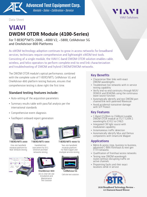
VIAVI Solutions Data SheetVIAVIDWDM OTDR Module (4100-Series)For T-BERD®/MTS-2000, -4000 V2, -5800, CellAdvisor 5Gand OneAdvisor-800 PlatformsAs xWDM technology adoption continues to grow in access networks for broadbandservices, technicians require comprehensive and lightweight xWDM test tools.Consisting of a single module, the VIAVI C-band DWDM OTDR solution enables cable,wireless, and telco operators to perform complete end-to-end link characterizationand troubleshooting of DWDM and hybrid CWDM/DWDM networks.Key Benefitsy Characterize fiber links with exactDWDM wavelengthsy Troubleshoot live networks with in-servicetesting capabilityy Verify end-to-end continuity through MUX/DEMUX and ROADMs using the continuouswave source functiony Automatically identify and test DWDM portchannel/link with patented Wavescany Avoid accidental transceiver damagewith SFP ProtectKey Featuresy C-Band (1528nm to 1568nm) tunableDWDM OTDR module at ITU-T G.694.1wavelengths (CH12 to CH62)y Integrated CW light source withmodulation capabilityy Instantaneous traffic detectiony Automatically identify Mux and Demuxcomponents with SmartLink MapperApplicationsy Metro & access rings, business to business,advanced C-RAN fronthauls & next genFTTH networksy Qualification of fronthaul access networksy Testing new DWDM wavelengthroutes without disrupting traffic onactive channelsy Pinpointing faults and their exactlocations while in serviceThe DWDM OTDR module’s optical performance, combinedwith the complete suite of T-BERD/MTS, CellAdvisor 5G andOneAdvisor-800 platform testing features, ensures thatcomprehensive testing is done right the first time.Standard testing features include:y Auto-setting of the acquisition parametersy Summary results table with pass/fail analysis per theinternational standardsy Comprehensive event diagnosisy FastReport onboard report generationT-BERD/MTS-2000One-slot handheldmodular platform forfiber network testingHandheld testinstrument for 10 GEthernet and fibernetworks testingTwo-slot handheldmodular platformfor fiber/copper andmultiple services testingT-BERD/MTS-4000 V2T-BERD/MTS-5800CellAdvisor 5GCell site test solutionOneAdvisor-800All-in-One Cell-siteInstallation andMaintenanceT est Solution2020 Broadband Technology Review ‒4.5 Diamond Award Winner2 VIAVI T-BERD/MTS 4100 Series DWDM OTDR ModuleSpecifications (typical at 25°C)2. The one-way difference between the extrapolated backscattering level at the start of the fiber and the RMS noise level, after 3 minutes averaging and using the largest pulsewidth.3. Measured at ±1.5 dB down from the peak of an unsaturated reflective event using the shortest pulsewidth.4. Measured at ±0.5 dB from the linear regression using a FC/PC reflectance and using the shortest pulsewidth.5. Subtract 3 dB when used in modulation mode (270/330/1/2 kHz).For more information on the VIAVI T-BERD/MTS-2000/-4000 V2/-5800, CellAdvisor 5G and OneAdvisor-800 test platforms, refer to their respective datasheets.Ordering Information4100 DWDM OTDR Modules Tunable DWDM OTDR Module - PCE41DWDMC-PC Tunable DWDM OTDR Module - APCE41DWDMC-APC Wavescan® SW option for DWDM OTDR Module EWAVESCAN SFP Protect SW option for DWDM OTDR Module ESFPPROTECT Optical Adapters Switchable AdaptersEUSCADS,EUSCADS-APC,EUFCADS,EULCADS, EULCADS-APC。
- 1、下载文档前请自行甄别文档内容的完整性,平台不提供额外的编辑、内容补充、找答案等附加服务。
- 2、"仅部分预览"的文档,不可在线预览部分如存在完整性等问题,可反馈申请退款(可完整预览的文档不适用该条件!)。
- 3、如文档侵犯您的权益,请联系客服反馈,我们会尽快为您处理(人工客服工作时间:9:00-18:30)。
A -T A R M A T U R E N -T E C H N I K G M
B H
Isolating, Control Valves and Turbine Bypass Systems for the Electric Power Industry, Steam Plant Utilities and Process Industry Adress : A-T Armaturen-Technik GmbH, Duisburger Straße 375, D-46049 Oberhausen, Germany, Phone +49 208 833 1700, FAX +49 208 833 1755, E-mail: sales@, home page: Page 1 of 1 issued: AG checked: BE Issued date 13.01.2004 3:53
file: BuW-Demontage-SV-UV.doc
Preheater Bypass System
1 De-assembling of the UV and SV valves
Before de-assembling, be sure that the complete system is pressure less. All electric components have to be removed.
1. disconnect pilot line by loosening flange connection (28)
2. remove cap nut (44)
3. remove screws (53) and Guiding device (18,19)
4. take off complete console with handwheel set.
5. Pull insert (2) out of body (1) for seat and plug inspection
For pistonring exchange please proceed from step 4 as follows
6. loosen hexagon socket head cap screw (50)
7. loosen packing bridge (14) and remove
8. re-install the complete console, but keep distance to closure part (2) and body, by placing 4 cap
nuts between both parts
9. place coupling (55) and tear out topflange (12) by turning the handwheel into fully open position
10. remove console again and de-assemble cylinder and insert (2)
11. remove plug by taking out screw ring (9)
12. remove complete stem
After de-assembly the following checks have to be accomplished:
- Check the stuffing-box for surface quality and dimensions
- Check stem surface
- Check the base bushing and gland for surface
- Check the sealing surface of plug and seat
2 Assembling of the UV and SV valves
The re-assembling of the valves has to be executed in reverse order as described under point 1 above.
Attention: in order not to damage the sealing ring (34) take care during inserting the assembled trim into the body (use grease for sliding), by using console as lifting device.
Caution:
With longer downtimes (over 4 weeks) it is advisable to de-assemble the pressure device, conserve all parts with water-soluble oil and to remove the packings as well as the cap seal. Assembling the pressure device af-ter a de-assembly for revision purposes all seals are to be renewed.
All work is to be accomplished only by our trained specialized engineers.
Assembly instruction。