IRHQ593110中文资料
爱士顿199158产品目录号199158爱士顿摩尔系列PKZM0电动机保护电路断路器,5.5 kW,

Eaton 199158Eaton Moeller® series PKZM0 Motor-protective circuit-breaker, 5.5kW, 8 - 12 A, Push in terminalsSpécifications généralesEaton Moeller® series PKZM0 Motor-protective circuit-breaker199158401508197242575 mm109 mm45 mm0.348 kgIEC/EN 60947VDE 0660ULCSAIEC/EN 60947-4-1UL 60947-4-1CSA-C22.2 No. 60947-4-1-14 CEUL File No.: E36332UL Category Control No.: NLRV CSA File No.: 165628CSA Class No.: 3211-05PKZM0-12-PIProduct Name Catalog NumberEANProduct Length/Depth Product Height Product Width Product Weight Certifications Model CodeTurn buttonPhase-failure sensitivity (according to IEC/EN 60947-4-1, VDE 0660 Part 102)Motor protectionPhase failure sensitiveThree-pole 100,000 operations100,000 OperationsDIN rail (top hat rail) mounting optionalCan be snapped on to IEC/EN 60715 top-hat rail with 7.5 or15 mm height.40 Operations/hIII3Motor protective circuit breakerFinger and back-of-hand proof, Protection against direct contact when actuated from front (EN 50274)6000 V AC25 g, Mechanical, according to IEC/EN 60068-2-27, Half-sinusoidal shock 10 msAlso motors with efficiency class IE3Branch circuit: Manual type E if used with terminal, or suitable for group installations, (UL/CSA)-5 - 40 °C to IEC/EN 60947, VDE 0660-25 - 55 °C, Operating range≤ 0.25 %/K, residual error for T > 40°Actuator type Features Functions Number of poles Lifespan, electricalLifespan, mechanicalMounting MethodMounting positionOperating frequencyOvervoltage categoryPollution degreeProduct categoryProtectionRated impulse withstand voltage (Uimp) Shock resistanceSuitable forTemperature compensationAltitude Terminal capacity (flexible)Max. 2000 m-25 °C55 °C25 °C40 °C40 °C80 °CDamp heat, constant, to IEC 60068-2-78 Damp heat, cyclic, to IEC 60068-2-301 x (1 - 6) mm²18 - 812 mm50 Hz60 Hz12 A3 kW5.5 kW690 V690 V12 A18 kA, 600 V High Fault, Fuse, SCCR (UL/CSA)600 A, 600 V High Fault, max. Fuse, SCCR (UL/CSA) 18 kA, 600 V High Fault, CB, SCCR (UL/CSA)600 A, 600 V High Fault, max. CB, SCCR (UL/CSA)18 kA, 240 V, SCCR (UL/CSA)18 kA, 480 Y/277 V, SCCR (UL/CSA)18 kA, 600 Y/347 V, SCCR (UL/CSA)65 kA, 240 V, SCCR (UL/CSA)65 kA, 480 Y/277 V, SCCR (UL/CSA)0.5 HP 3 HP2 HP3 HP 7.5 HPAmbient operating temperature - minAmbient operating temperature - maxAmbient operating temperature (enclosed) - min Ambient operating temperature (enclosed) - max Ambient storage temperature - minAmbient storage temperature - maxClimatic proofing Terminal capacity (solid/stranded AWG)Stripping length (main cable)Rated frequency - minRated frequency - maxRated operational current (Ie)Rated operational power at AC-3, 220/230 V, 50 Hz Rated operational power at AC-3, 380/400 V, 50 Hz Rated operational voltage (Ue) - minRated operational voltage (Ue) - maxRated uninterrupted current (Iu)Short-circuit current rating (group protection) Short-circuit current rating (type E)Short-circuit release Assigned motor power at 115/120 V, 60 Hz, 1-phase Assigned motor power at 200/208 V, 60 Hz, 3-phase Assigned motor power at 230/240 V, 60 Hz, 1-phase Assigned motor power at 230/240 V, 60 Hz, 3-phase Assigned motor power at 460/480 V, 60 Hz, 3-phaseBasic device fixed 15.5 x Iu, Trip Blocks186 A, Irm, Setting range max.± 20% tolerance, Trip blocks10 HPPush in terminals0 0 012 A12 AOverload trigger: tripping class 10 A6.64 W0 W0 W0 WMeets the product standard's requirements. Meets the product standard's requirements. Meets the product standard's requirements. Meets the product standard's requirements. Meets the product standard's requirements.DA-DC-00004919.pdfDA-DC-00004889.pdfETN.PKZM0-12-PI.edzIL122024ZUpkzm0_pi.stpmotorschutzschalter_bis_32a_pi.dwg121X002121X042eaton-manual-motor-starters-pkzm-pkzm0-dimensions.eps eaton-manual-motor-starters-pkz-dimensions-002.eps eaton-manual-motor-starters-pkz-dimensions.eps Assigned motor power at 575/600 V, 60 Hz, 3-phase ConnectionNumber of auxiliary contacts (change-over contacts) Number of auxiliary contacts (normally closed contacts) Number of auxiliary contacts (normally open contacts)Overload release current setting - min Overload release current setting - max Tripping characteristicEquipment heat dissipation, current-dependent PvidHeat dissipation capacity PdissHeat dissipation per pole, current-dependent PvidStatic heat dissipation, non-current-dependent Pvs10.2.2 Corrosion resistance10.2.3.1 Verification of thermal stability of enclosures10.2.3.2 Verification of resistance of insulating materials to normal heat10.2.3.3 Resist. of insul. mat. to abnormal heat/fire by internal elect. effects10.2.4 Resistance to ultra-violet (UV) radiation Declarations of conformity eCAD model Instructions d'installation mCAD modelSchémas10.2.5 LiftingDoes not apply, since the entire switchgear needs to be evaluated.10.2.6 Mechanical impactDoes not apply, since the entire switchgear needs to be evaluated.10.2.7 InscriptionsMeets the product standard's requirements.10.3 Degree of protection of assembliesDoes not apply, since the entire switchgear needs to be evaluated.10.4 Clearances and creepage distancesMeets the product standard's requirements.10.5 Protection against electric shockDoes not apply, since the entire switchgear needs to be evaluated.10.6 Incorporation of switching devices and components Does not apply, since the entire switchgear needs to be evaluated.10.7 Internal electrical circuits and connectionsIs the panel builder's responsibility.10.8 Connections for external conductorsIs the panel builder's responsibility.10.9.2 Power-frequency electric strengthIs the panel builder's responsibility.10.9.3 Impulse withstand voltageIs the panel builder's responsibility.10.9.4 Testing of enclosures made of insulating materialIs the panel builder's responsibility.10.10 Temperature riseThe panel builder is responsible for the temperature rise calculation. Eaton will provide heat dissipation data for the devices.10.11 Short-circuit ratingIs the panel builder's responsibility. The specifications for the switchgear must be observed.10.12 Electromagnetic compatibilityIs the panel builder's responsibility. The specifications for the switchgear must be observed.Eaton Corporation plc Eaton House30 Pembroke Road Dublin 4, Ireland © 2023 Eaton. Tous droits réservés. Eaton is a registered trademark.All other trademarks areproperty of their respectiveowners./socialmediaThe device meets the requirements, provided the information in the instruction leaflet (IL) is observed.10.13 Mechanical function。
паркер汉尼夫公司水力系列产品目录说明书

ABV101............Accumulator Bleed-Down Valve......................MV15-MV17 CDP161............Double P.O. Check Valves..................................LH85-LH86 CDPH103..........Double P.O. Check Valves..................................LH83-LH84 CP044P............Single P.O. Check Valves...................................LH46-LH48 CP074P............Single P.O. Check Valves...................................LH49-LH51 CP084P............Single P.O. Check Valves...................................LH52-LH54 CPC101P..........Pilot-to-Close Check Valves...............................LH64-LH66 CPC161P..........Pilot-to-Close Check Valves...............................LH67-LH69 CPD084P..........Double P.O. Check Valves..................................LH80-LH82 CPH064P..........Single P.O. Check Valves...................................LH55-LH57 CPH104P..........Single P.O. Check Valves...................................LH58-LH60 CPH124P..........Single P.O. Check Valves...................................LH61-LH63 CS041B............Shuttle Valves....................................................LH87-LH89 CSH101B..........Shuttle Valves....................................................LH90-LH92 CSP161............Single P.O. Check Valves...................................LH78-LH79 CSPH103..........Single P.O. Check Valves...................................LH76-LH77 CV041P............Check Valves.........................................................LH1-LH3 CV081P &091P.................Check Valves.........................................................LH4-LH6 CV082P............Check Valves.........................................................LH7-LH9 CV101P............Check Valves.....................................................LH10-LH12 CV102P............Check Valves.....................................................LH13-LH15 CV103P............Check Valves.....................................................LH16-LH18 CVH061P..........Check Valves.....................................................LH25-LH27 CVH071P..........Check Valves.....................................................LH28-LH30 CVH081P &091P.................Check Valves.....................................................LH31-LH33 CVH103P..........Check Valves.....................................................LH34-LH36 CVH084P..........Check Valves.....................................................LH37-LH39 CVH104P..........Check Valves.....................................................LH40-LH42 CVH121P..........Check Valves.....................................................LH43-LH45 CVH161P..........Check Valves.....................................................LH19-LH21 CVH201P..........Check Valves.....................................................LH22-LH24 CVO101P..........Vent-to-Open Check Valves...............................LH70-LH72 CVO161P..........Vent-to-Open Check Valves...............................LH73-LH75 DF083...............Sol. Operated, P.C. Proportional Flow Cont...........PV1-PV4 DF092C............Sol. Operated, P.C. Proportional Flow Cont...........PV5-PV8 DF092N............Sol. Operated, P.C. Proportional Flow Cont.........PV9-PV12 DF102C............Sol. Operated, P.C. Proportional Flow Cont.......PV13-PV16 DF102N............Sol. Operated, P.C. Proportional Flow Cont.......PV17-PV20 DF102P............Sol. Operated, P.C. Proportional Flow Cont.......PV21-PV23 DF122...............Sol. Operated, P.C. Proportional Flow Cont.......PV24-PV27 DF161C............Solenoid Operated, Throttle Valves....................PV28-PV31 DF201C............Solenoid Operated, Throttle Valves....................PV32-PV35 DH082..............Pilot Operated, 2-Way Valves............................DC22-DC24 DH103..............Pilot Operated, Directional Valves......................DC25-DC28 DL081..............Manual, Poppet-Type, 2-Way Valves.....................DC1-DC3 DL101..............Manual, Poppet-Type, 2-Way Valves.....................DC4-DC6 DL102..............Manual, Spool-Type, 2-Way Valves.......................DC7-DC9 DL103..............Manual, Spool-Type, 3-Way Valves...................DC10-DC12 DL104..............Manual, Spool-Type, 4-Way Valves...................DC13-DC15 DM103.............Manual, Rotary, 3-Way Valves...........................DC16-DC18 DM104.............Manual, Rotary, 4-Way Valves...........................DC19-DC21 DPR083B..........Sol. Operated, Proportional Pres. Reducing......PV36-PV39 DPR083C..........Sol. Operated, Proportional Pres. Reducing......PV40-PV43 DPR083C30......Sol. Operated, Proportional Pres. Reducing......PV44-PV47 DPR083N.........Sol. Operated, Proportional Pres. Reducing......PV48-PV51 DPR103C..........Sol. Operated, Proportional Pres. Reducing......PV52-PV55DPR104C10......Sol. Operated, Proportional Pres. Reducing......PV56-PV59 DS085..............Solenoid, Spool-Type, 4-Way, 3-Pos.............DC127-DC130 DS086C6Mand 096............Sol., Bi-Directional, Poppet-Type, 2-Way.......DC148-DC151 DS105..............Solenoid, Spool-Type, 4-Way, 3-Pos.............DC131-DC134 DS161..............Solenoid, Poppet-Type, 2-Way Valves...............DC56-DC59 DS162..............Solenoid, Spool-Type, 2-Way Valves.................DC84-DC87 DS123B............Solenoid, Spool-Type, 3-Way Valves.............DC104-DC106 DS163..............Solenoid, Spool-Type, 3-Way Valves.............DC107-DC110 DS201..............Solenoid, Poppet-Type, 2-Way Valves...............DC60-DC63 DS083BP3........Solenoid, Poppet-Type, 3-Way Valves...............DC64-DC67 DSH08D1C.......Solenoid, Poppet-Type, 2-Way Valves...........DC139-DC141 DSH08D6C.......Solenoid, Poppet-Type, 2-Way Valves...........DC145-DC147 DSH081 & 091.Solenoid, Poppet-Type, 2-Way Valves...............DC36-DC39 DSH082 & 092.Solenoid, Spool-Type, 2-Way Valves.................DC72-DC75 DSH083............Solenoid, Spool-Type, 3-Way Valves.................DC92-DC95 DSH084............Solenoid, Spool-Type, 4-Way Valves.............DC115-DC118 DSH085............Solenoid, Spool-Type, 4-Way, 3-Pos.............DC135-DC138 DSH101............Solenoid, Poppet-Type, 2-Way Valves...............DC44-DC47 DSH102............Solenoid, Spool-Type, 2-Way Valves.................DC80-DC83 DSH103............Solenoid, Spool-Type, 3-Way Valves.............DC100-DC103 DSH104............Solenoid, Spool-Type, 4-Way Valves.............DC123-DC126 DSH106C6........Sol., Bi-Directional, Poppet-Type, 2-Way.......DC156-DC159 DSH121............Solenoid, Poppet-Type, 2-Way Valves...............DC52-DC55 DSL08D6C........Sol., Bi-Directional, Poppet-Type, 2-Way.......DC142-DC144 DSL080DC........Soft Seat, Direct Act., Poppet-Type, 2-Way.......DC29-DC31 DSL081 & 091.Solenoid, Poppet-Type, 2-Way Valves...............DC32-DC35 DSL082 & 092.Solenoid, Spool-Type, 2-Way Valves.................DC68-DC71 DSL083............Solenoid, Spool-Type, 3-Way Valves.................DC88-DC91 DSL084............Solenoid, Spool-Type, 4-Way Valves.............DC111-DC114 DSL101............Solenoid, Poppet-Type, 2-Way Valves...............DC40-DC43 DSL102............Solenoid, Spool-Type, 2-Way Valves.................DC76-DC79 DSL103............Solenoid, Spool-Type, 3-Way Valves.................DC96-DC99 DSL104............Solenoid, Spool-Type, 4-Way Valves.............DC119-DC122 DSL106C6........Sol., Bi-Directional, Poppet-Type, 2-Way.......DC152-DC155 DSL121............Solenoid, Poppet-Type, 2-Way Valves...............DC48-DC51 EHVC................Electrohydraulic Valve Controller.......................PV92-PV99 ERV091C..........Solenoid Operated, Proportional P.C.................PV60-PV63 ERV091N..........Solenoid Operated, Proportional P.C.................PV64-PV67 ERV092N..........Solenoid Operated, Proportional P.C.................PV68-PV71 ERV101C..........Solenoid Operated, Proportional P.C.................PV72-PV75 ERV101N..........Solenoid Operated, Proportional P.C.................PV76-PV79 ERV102N..........Solenoid Operated, Proportional P.C.................PV80-PV83 ERV121N..........Solenoid Operated, Proportional P.C.................PV84-PV87 ERV161N..........Solenoid Operated, Proportional P.C.................PV88-PV91 FA101...............Pressure Compensated Flow Control................VC16-VC18 FC101...............Pressure Compensated Flow Control................VC22-VC24 FCP101.............Priority-Type, P.C. Valves...................................VC38-VC40 FCPH121..........Priority-Type, P.C. Valves...................................VC41-VC43 FCR101............Restrictive-Type, P.C. Valves..............................VC29-VC31 FCR121............Restrictive-Type, P.C. Valves..............................VC32-VC34 FCR161............Restrictive-Type, P.C. Valves..............................VC35-VC37 FDC101............Flow Divider/Combiner Valves...........................VC19-VC21 FL101...............Filter Cartridge.....................................................MV7-MV9 FP101...............Priority-Type, P.C. Flow Control Valves..............VC47-VC50 FPR101............Priority-Type, P.C. Flow Control Valves..............VC51-VC53 FR101...............Restrictive-Type, P.C. Flow Control Valves.........VC44-VC46FV101 & 102 .... Flow Control Valves ........................................... VC25-VC28 HLSVH101........Hi-Lo Unloading Valve.....................................MV10-MV12 HP101..............Hand Pump.....................................................MV13-MV14 NV102..............Needle Valves........................................................VC7-VC9 NV161..............Needle Valves....................................................VC10-VC12 NV162..............Needle Valves....................................................VC13-VC15 NVH081............Needle Valves........................................................VC1-VC3 NVH101............Needle Valves........................................................VC4-VC6 Offer of Sale............................................................................................TI15 P10-2*.............Cavity Plugs................................................................MV19 PDS101............Pressure Sensing..............................................PC67-PC69 PDS161............Pressure Sensing..............................................PC70-PC72 PMK101...........Panel Mount Kit..........................................................MV18 PN 812724.......Block Off Plate............................................................MV20 PR103..............Pressure Reducing/Relieving Valves.................PC91-PC93 PRCH101..........Pressure Reducing/Relieving Valves With.........................PC79-PC81PRH081............P.O. Pressure Reducing/Relieving Valves..........PC73-PC75 PRH082............P.O. Pressure Reducing Valves..........................PC94-PC96 PRH101............P.O. Pressure Reducing/Relieving Valves..........PC76-PC78 PRH102............P.O. Pressure Reducing Valves..........................PC97-PC99 PRH121............P.O. Pressure Reducing/Relieving Valves..........PC82-PC84 PRH121V..........P.O. Pressure Reducing/Relieving Valves..........PC85-PC87 PRH122............P.O. Pressure Reducing Valves......................PC100-PC102 PRH161............P.O. Pressure Reducing/Relieving Valves..........PC88-PC90 PRH162............P.O. Pressure Reducing Valves......................PC103-PC105PRS102............Pressure Reducing Spool Valves...................PC106-PC108PRS162............Pressure Reducing Spool Valves...................PC109-PC111 RAH081 & 091.P.O. Relief Valves...............................................PC49-PC51 RAH101............P.O. Relief Valves...............................................PC52-PC54 RAH101V..........P.O. Ventable Relief Valves................................PC55-PC57 RAH121............P.O. Relief Valves...............................................PC58-PC60 RAH161............P.O. Relief Valves...............................................PC61-PC63 RAH201............P.O. Relief Valves...............................................PC64-PC66 RASPH21.........Subplate/Relief Valve...........................................MV1-MV3 RASPH31.........Subplate/Relief Valve...........................................MV4-MV6 RD042..............Direct Acting Relief Valves.....................................PC7-PC9 RD072..............Direct Acting Relief Valves.................................PC13-PC15 RD102..............Direct Acting Relief Valves.................................PC19-PC21 RD163..............Direct Acting Relief Valves.................................PC31-PC33 RDH062............Direct Acting Relief Valves.................................PC10-PC12 RDH081............Direct Acting Relief Valves.....................................PC1-PC3 RDH082............Direct Acting Relief Valves.................................PC16-PC18 RDH083............Direct Acting Relief Valves.................................PC22-PC24 RDH101............Direct Acting Relief Valves.....................................PC4-PC6 RDH103............Direct Acting Relief Valves.................................PC25-PC27 RDH104............Differential Relief Valves With..........................................PC34-PC36 RDCH103.........Direct Acting Relief Valves With..........................................PC28-PC30PC139-PC141 SVCH101..........Sequence Valves w/Free Rev. Flow Check.....PC118-PC120 SVH081............Sequence Valves............................................PC112-PC114 SVH082............P.O. Sequence Valves....................................PC127-PC129 SVH101............Sequence Valves............................................PC115-PC117 SVH102............P.O. Sequence Valves....................................PC130-PC132 SVH121............Sequence Valves............................................PC121-PC12308 & 09............Coils 1/2″ I.D..........................................................CL1-CL2 DF102P &DPR104C10......Coils 1/2″ I.D..........................................................CL3-CL4 10, 12,16 & 20............Coils 5/8″ I.D..........................................................CL5-CL6 12 & 16............Coils 1″ I.D.............................................................CL7-CL8 08 & 09............Unicoils 1/2″ I.D...................................................CL9-CL10 10 & 12............Unicoils 5/8″ I.D.................................................CL11-CL12 08 & 09............Waterproof Coils 1/2″ I.D............................................CL13 10 & 12............Waterproof Coils 5/8″ I.D............................................CL14 Installation Data.........................................................................................TI1 04.....................Two and Three Way Cavity Details..................................TI206.....................Two and Three Way Cavity Details..................................TI307.....................Two and Three Way Cavity Details..................................TI408.....................Two, Three and Four Way Cavity Details...................TI5-TI609.....................Two Way Cavity Detail....................................................TI710.....................Two, Three and Four Way Cavity Details...................TI8-TI9 12.....................Two, Three and Four Way Cavity Details...............TI10-TI11 16.....................Two, Three and Four Way Cavity Details...............TI12-TI13 20.....................Two Way Cavity Detail..................................................TI14 B04-2**...........Single Function, Two Step Bodies.........................VB1-VB2 B04-3**...........Single Function, Three Step Bodies.......................VB3-VB4 B06-2**...........Single Function, Two Step Bodies.........................VB5-VB6 B06-3**...........Single Function, Three Step Bodies.......................VB7-VB8 B07-2**...........Single Function, Two Step Bodies.......................VB9-VB10 B07-3**...........Single Function, Three Step Bodies...................VB11-VB12 B08-2**...........Single Function, Two Step Bodies.....................VB13-VB14 B08-3**...........Single Function, Three Step Bodies...................VB15-VB16 B08-4**...........Single Function, Four Step Bodies.....................VB17-VB18 B09-2**...........Single Function, Two Step Bodies.....................VB19-VB20 B10-2**...........Single Function, Two Step Bodies.....................VB21-VB22 B10-2T**.........Single Function, Two Step Bodies.....................VB23-VB24 B10-3**...........Single Function, Three Step Bodies...................VB25-VB26 B10-3L**.........Single Function, Three Step Bodies...................VB27-VB28 B10-4**...........Single Function, Four Step Bodies.....................VB29-VB30 B12-2**...........Single Function, Two Step Bodies.....................VB31-VB32 B12-3**...........Single Function, Three Step Bodies...................VB33-VB34 B12-4**...........Single Function, Four Step Bodies.....................VB35-VB36 B16-2**...........Single Function, Two Step Bodies.....................VB37-VB38 B16-3**...........Single Function, Three Step Bodies...................VB39-VB40 B16-3S**.........Single Function, Three Step Bodies...................VB41-VB42 B20-2**...........Single Function, Two Step Bodies.....................VB43-VB44 Single Function BodiesCavity DetailsCartridge Valve CoilsSVH122............P.O. Sequence Valves....................................PC133-PC135 SVH161............Sequence Valves............................................PC124-PC126 SVH162............P.O. Sequence Valves....................................PC136-PC138 TR081..............Thermal Relief Valves....................................PC142-PC144 VF101...............Velocity Fuses....................................................VC54-VC56 XR101..............Cross-Over Relief Valves...................................PC37-PC39 XRDH101.........Cross-Over Relief Valves...................................PC40-PC42 XRDH102.........Dual Relief Valves w/Anti-Cavitation Checks......PC43-PC45 XRDH103.........Cross-Over Relief Valves...................................PC46-PC48。
湿度传感器HS1101
湿度传感器HS11011引言湿度传感器是根据某种物质从其周围空气中吸收水分后引起的物理或化学性质的变化,从而获得该物质的吸水量和周围空气的湿度。
湿度传感器分为电阻式和电容式两种,产品的基本形式都是在基片涂覆感湿材料形成感湿膜。
空气中的水蒸汽吸附于感湿材料后,元件的阻抗、介质常数发生很大的变化,从而制成湿敏元件。
湿敏电容一般是用高分子薄膜电容制成的,由于它具有灵敏度高、产品互换性好、响应速度快、湿度的滞后量小、便于制造、容易实现小型化和集成化,其精度一般比湿敏电阻要低一些。
但电阻对温度的敏感因而限制了器件在较大温度范围内的应用,因而电容湿度传感器越来越受到重视。
2 湿敏元件及变送器芯片特性目前,生产湿敏电容的主要厂家是法国Humirel 公司。
它生产的HS1101 测量范围是0%,100%RH,电容量由162PF 变到200PF,其误差不大于?2%RH;响应时间小于5S;湿度系数为0.34PF/?;年漂移量0.5%RH/年,长期稳定。
图1 为HS1101湿敏电容的湿度-电容响应曲线。
湿度变送器采用了美国 BB 公司生产的XTR105芯片,该变送器具有以下特点:a 工作范围宽;b 测量精度高;c 电路简单;d 可靠性好,使用寿命长;e 抗干扰能力强;f 工作温度范围宽(-40,+85?)3 湿度测量电路HS1101在电路中相当于一个电容器件,它的电容量随着所测空气湿度的增加而增大,为了能将电容的变化转换成电压的变化,我们设计了振荡电路、消除零点电容影响电路、整流电路、积分电路、电压—电流转换电路、放大电路等,其工作原理简图如图2 所示。
3.1 振荡电路振荡电路的作用是将电容的变化量转化为频率可变的方波。
由图3 可知,这是一个非对称多谐振荡器。
或非门G1 工作在电压传输特性的转折区,把它的输出电压直接连接到或非门G2 的输入端。
G2即可得到一个介于高低电平之间的静态偏置电压,从而使G2 的静态工作点也处于电压传输特性转折区上。
哈纳刀形液滴传感器水浊度计(HI 93703-11)用户手册说明书

2Dear Customer,Thank you for choosing a Hanna product.Please read this instruction manual carefully before using the instrument.This manual will provide you with the necessary information for the correct use of the instrument.If you need additional technical information, do not hesitate to e-mail us at ******************directives.Preliminary Examination ............................3General Description....................................3Principle of Operation .................................5Functional Description................................6Specifications ............................................7Operational Guide ......................................8Measurement Procedure.......................8Log-on-demand ...................................11Cleaning Logged Data .........................11Viewing Logged Data ..........................12Viewing and setting Date and Time .....12Error Codes.........................................13Ensure Accurate Measurements.............14Sources of Interference.......................15Calibration................................................16Calibration Procedure..........................16Viewing Calibration Date .....................18Ensure Accurate Calibration................18Standard Suspension..........................19Battery Replacement ...............................20PC Connection.........................................21Accessories.............................................22Warranty.. (23)23Recommendations for UsersBefore using this product, make sure that it is entirely suitable for the environment in which it is used.Operation of this instrument in residential area could cause unacceptable interferences to radio and TV equipments, requiring the operator to take all necessary steps to correct interferences.Any variation introduced by the user to the supplied equipment may degrade the instrument's EMC performance.To avoid electrical shock, do not use this instrument when voltages at the measurement surface exceed 24 Vac or 60 Vdc.To avoid damages or burns, do not perform any measurement in microwaveovens.All Hanna Instruments meters are warranted for two years against defects in workmanship and materials when used for their intended purpose and maintained according to instruc-tions. This warranty is limited to repair or replacement free of charge. Damages due to accidents, misuse, tampering or lack of pre-scribed maintenance are not covered.If service is required, contact the dealer from whom you purchased the instrument. If under warranty, report the model number, date of purchase, serial number and the nature of the failure. First obtain a Returned Goods Authori-zation number from the Customer Service de-partment, then return the instrument with the Authorization # included along with shipment costs prepaid. If the repair is not covered by the warranty, you will be notified of the charges.When shipping any instrument, make sure it is properly packaged for complete protection.All rights are reserved. Reproduction in whole or in part is prohibited without the written consent of the copyright owner.3Remove the instrument from the packing material and examine it to make sure that no damage has occurred during shipping. If there is any damage,notify your Dealer.HI 93703-11 is supplied complete with:•Glass cuvet with cap •Batteries (4 x 1.5V AA)•Instruction manualNote : Save all packing material until you are sure that the instrument functions correctly. Any defective item must be returned in its original packaging with the supplied accessories.With HI 93703-11 turbidity measurements can be performed with high precision in the field as well as in the laboratory. HI93703-11 turbidity meter is a microprocessor-based instrument used to determine the turbidity of water and waste-water. The meter covers a 0-1000 FTU range in two scales: 0.00 to 50.00 FTU and 50to 1000 FTU. The autoranging feature of the instrument sets the appropriate range for the measurement.HI 93703-11 also includes a real-time clock and log-on-demand capability. The PC communication is made through a serial port of your computer and the 5-pin socket on the meter.Note:HI 93703-11 has been designedaccording to the ISO 7027 International Standard, consequently the turbidity measurement units are expressed in FTU (Formazine Turbidity Unit). FTU is identical to the other internationally recognized unit: NTU (NephelometricTurbidity Unit).22HI 731318Tissue for wiping cuvets (4pcs)HI 731321Spare glass cuvet (4pcs)HI 731313Maintenance kit: rugged carrying case including HI 93703-0 and HI 93703-10calibration solutions, HI 93703-50 cuvet cleaning solution, 1tissue for wiping cuvets and 2cuvetsHI 93703-0AMCO-AEPA-1 @0 FTU*calibration solution, 30 mL HI 93703-05AMCO-AEPA-1 @500 FTU*calibration solution, 30 mL HI 93703-10AMCO-AEPA-1 @10 FTU*calibration solution, 30 mL HI 93703-50Cuvet cleaning solution, 230mLHI 92000Windows ® compatible software HI 920011Serial cable for PC connection (5 to 9-pin)* 1 FTU = 1 NTU4The meter is housed in a rugged and lightweight case, with an easy-to-read LCD.To save battery-life, the instrument is equipped with an automatic shut-off feature which is activated after 5-minutes of non-use. This fea-ture is disabled when the meter is connected to the serial port of the computer.All operations can be carried out with only five keys and troubleshooting functions can be performed with displayed error code guides.A positive-locking system guarantees that the cuvet is firmly placed in the cell.The keypad is water-resistant and can be wiped with a moist cloth for quick cleanups.Two or three point calibration (0,10, 500 FTU*)can be easily performed using available stan-dards, and the last calibration date is auto-matically stored for future retrivial.We have chosen 10 FTU * as the standard calibration point because it best fits the water turbidity measurements in different applications, from drinking water to waste-water treatment.HANNA instruments ® uses the primary stan-dard AMCO-AEPA-1 to avoid all formazine-related problems. Formazine is a toxic, un-stable substance, which requires particular care:its standards have to be prepared only a few minutes before performing the calibration, and cannot be reused because of their short life.HANNA instruments ® standards are extremely stable, can be reused, and last up to six months, if free from contamination.HI 93703-11 can be used with both standards.* 1 FTU = 1 NTU21Battery replacement must only take place in a safe area and using 1.5V AA alkaline batteries.To install or replace the batteries, turn the unit off and remove the battery compartment cover on the raer of the meter.Insert the new batteries while paying attention to the polarity.After the batteries have been installed, close the battery cover and make sure the gasket is in place before tightening the 2 screws, to ensure a watertight seal.POTSTo communicate with the instrument through the HI 92000 software, use the HI 920011 cable (optional) to connect a serial port of your com-puter to the 5 pin connector of the meter.When connected the meter will maintain full functionality, being able to perform a data trans-fer while the meter is being operated.Notes :• Serial communication is not allowed when the meter is being calibrated.• The auto shut-off feature is also disabled when the meter is connected to a computer.5IR LEDCUVETLIGHT DETECTORLIGHT* 1 FTU = 1 NTUHI 93703-11 has been designed to perform measurements according to the ISO 7027 In-ternational Standard.The instrument functions by passing a beam of infrared light through a vial containing the sample being measured.A sensor, positioned at 90° with respect to the direction of light, detects the amount of light scattered by the undissolved particles present in the sample. The microprocessor converts such readings into FTU* values.As noted above, FTU unit is equal to the NTU unit. However, there are other known measure-ment units for turbidity: Jackson Turbidity Unit (JTU) based on the old method of Jackson's candle, and Silica Unit (mg /L of SiO 2). For your reference the conversion table between these measurement units is shown below:JTUFTU/NTUSiO 2 (mg/L)JTU119 2.5FTU/NTU 0.05310.13SiO 2 (mg /L)0.47.5120All components have been selected to mini-mize current drain without compromising func-tionality. In order to minimize the battery con-sumption, the meter is equipped with an auto-shut off function which switches the meter off after 5 minutes of non-use.The four 1.5V batteries guarantee 60 hours of working life (or 900 measurements).In order to obtain accurate measurements, the battery level is monitored every time the meter is switched on.In addition, a "LO BAT " indication will appear on the lower right corner of the display when the batteries are weak (<10%). All four batteries need to be replaced.When the batteries are too weak to ensure reliable measurements, the message 0% LO BAT appears for a few seconds, and then the meter will automatically switch itself off. Re-place the batteries immediately.61)Measurement cell2)LCD (Liquid Crystal Display)3)ON/OFF/CLR key, to turn the meter ON and OFF, and to clear log memory4)GLP/CAL key, to display last calibration date & time, and to enter calibration mode 5)STO/VIEW key, to store sample after read-ing, and to view log memory6)READ/DATE key, to perform measure-ments, and to display (toggle) current date/time7)ALT key, to activate the second functions (second function keys in orange)8)RS232 connector (5 pin)19* 1 FTU = 1 NTUSTANDARD SUSPENSIONPresently, there are only two recognized pri-mary standards: AMCO-AEPA-1 and formazine.Hanna supplies HI 93703-11 with the AMCO-AEPA-1 which has a much longer shelf life at all concentrations (approx. six months, if free from contamination). In addition, no special handling or disposal is required and a much higher stability of suspended particles has been ob-served.On the other hand, formazine is a toxic sub-stance, generated by a known carcinogen, with poor stability (particles flocculate and settle quickly). Lower concentrations change value within a few days or hours after dilution.The consistency of HI 93703-11 readings by using both standards has been separately es-tablished by Advanced Polymer Systems and Hanna Instruments.Additional documentation about the formazine standard and more complex calibration proce-dures is available upon request.•All glassware that comes into contact with standards should be maintained clean. Wash with the HI 93703-50 cleaning solution and rinse with HI 93703-0 or turbidity free water.•Rinse the vial twice with 5 ml of the liquid to be tested. This removes the effect of any previous liquid and any dust or foreign ob-jects that may be present inside. Gently pour the liquid down the side of the vial to reduce air bubbles (no mixing is required when HI 93703-0 and HI 93703-10 AMCO-AEPA-1standards are used).•Before inserting the vial into the instrument,wipe it with HI93703-70 or a soft, lint-free tissue. Handle vials so that no fingerprints can get on the areas where light passes (approx. bottom 2cm/1").7* 1 FTU = 1 NTURange 0.00 to 50.00 FTU *50 to 1000 FTU *Resolution 0.01 and 1 FTU *Accuracy±0.5 FTU* or±5% of reading (whichever is greater)Typical EMC Deviation ±2% FS Calibration 3 point (0, 10 and 500 FTU*)Light SourceInfrared LED Light Source Life Life of the instrument Light Detector Silicon photocellData Logging199 measurements, on-demand PC Connection Through serial port,using HI 920011 connection cable and HI 92000 Windows ® compatible software Battery Type4 x 1.5V AA alkaline batteries Battery Life Approx. 60 hours of continuous useor 900 measurementsAuto-offAfter 5 minutes of non-use Environment 0 to 50°C (32 to 122°F);RH max 95% non-condensingDimensions 220 x 82 x 66 mm (8.7 x 3.2 x 2.6")Weight510 g (1.1 lb.)18•After approximately 30 seconds the LCD will display "----".Now the instrument is calibrated and ready for use.NOTE: If "ERR1" is displayed, the calibra-tion data is maintained.VIEWING CALIBRATION DATE To display the last cali-bration time and date,press the GLP button to toggle through the date and time. If the display shows "FS", the instru-ment has factory calibra-tion settings loaded and no date will be displayed.VIEWING FIRMWARE VERSIONTo display the firmware version press and hold the ON/OFF key for approx. ten seconds (when turning the meter on).The firmware version will be displayedENSURE ACCURATE CALIBRATIONThe procedure below should be carefully fol-lowed during testing and calibration:8To prepare the instrument for taking measurements, first install the batteries (see Battery Replacement section on page 20) and then turn the instrument on.To maximize battery-life, the display is automatically switched off after 5-minutes of non-use. To reactivate the display, simply press the ON/OFF key.MEASUREMENT PROCEDURE:•Turn the meter on by pressing the ON/OFF key.•The meter will carry out a self-test display-ing a full set of figures.•The meter will carry out a battery test show-ing in percentage the battery life left.•When the LCD dis-plays “----” the meter is ready to measure.•Fill a clean cuvet up to one quar-ter inch (0.5cm) from its rim with the thoroughly agitated sample.•Allow sufficient time for bubbles to escape before securing the cap.Note:do not overtighten the cap.17•If "ERR1" appearson the LCD, please check the standard solution.•After approximately 30 seconds the meter will display 10.00, prompting the user to place the 10.00 FTU standard solution in the cuvet holder.•Place the 10.00 FTUstandard in the holder press CAL, SIP and CL will start blinking•After approximately30 seconds the meterwill display 500, asking the user to place the 500 FTU buffer solution in the cuvetholder.NOTE: At this point theuser can save the two point calibration setup by pressing ALT & CAL buttons,To perform a three point calibration, place the 500FTU standard solution in the cuvet holder.•Press CAL, SIP and CL will start blinking9NOTE: Wipe the cuvet thoroughly with a lint-free tissue (HI 93703-70) before in-serting into the measurement cell.The cuvet must be completely free of fingerprints and other oil or dirt, par-2 cm/1").•cu re ly int o t groove.•The mark on the cuvet cap should point towards the LCD.•onds.16To check the date of last calibration, simply press the GLP/CAL key. Press again to toggle between date and time.To make sure that the meter is calibrated, take a measure of a standard solution.The instrument can be calibrated at two or three points and a monthly calibration is recom-mended.CALIBRATION PROCEDURE •Turn the meter on and wait for the display to show "----".•Press the ALT & CALbuttons together. The "CAL" message will blink on the display 3times. The meter then enters the calibrationmode, displaying "0.00cl" and prompting the user to insert the 0.00FTU standard.••Press CAL, SIP and CL will start blinking10* 1 FTU = 1 NTU•Even though HI93703-11 covers a very wide range of turbidity values, for very accurate measurements of samples ex-ceeding 40FTU*, Standard Methods re-quire dilution. In such cases, the correct amount of HI 93703-0 or turbidity-free water to be added to the sample can be calculated as follows:Vos = 3000 / T where:Vos = volume of sample (mL) to becombined with HI 93703-0 to obtain the final volume of 100mL.T =HI 93703 reading (exceeding40FTU*)E.g.:HI 93703 reading = 200 FTU *3000 / 200 = 15 mL (Vos)15 mL (Vos)+85 mL (HI93703-0) = 100 mL At this point, take a sample of this solution and measure its turbidity.The correct turbidity value of the original sample will be:T n x 100 mL / Vos = T awhere:T n = new HI 93703 readingT a =actual turbidity value of the originalsample E.g.If T n = 27 FTU *T a = 27 FTU *x100 mL / 15 mL = 180 FTU *NOTE: Any sample taken above 1000 FTU will show out of range by blinking "1000".15* 1 FTU = 1 NTUhours (the sample needs to be kept at room temperature prior to the analysis).•To obtain a representative sample, gently,but thoroughly, mix it before samples are taken. Do not shake (to prevent air bubbles)and do not let the sample settle.•It is recommended to calibrate the meter with the supplied HI 93703-10 @10 FTU* stan-dard at least once a month or more frequently for greater accuracy.•Before inserting vials into the instrument,wipe them with HI 93703-70 or a soft, lint-free tissue. Handle vials so that no finger-prints get on the areas where light passes (approx. the bottom 2 cm/1 inch).If you experience any problems in taking mea-surements, contact your dealer or the nearest Hanna Customer Service Center.SOURCES OF INTERFERENCE•Presence of floating debris and coarse sedi-ments which settle out rapidly will give false readings.•The infrared light source used for HI 93703-11 turbidity meter, complies with the ISO 7027 International Standard and can effec-tively minimize any errors due to colored dissolved substances. This effect, called "true color", is a common interference for most commercially available instruments operating in the range of visible light.•Air bubbles and the effect of vibrations that disturb the surface of the sample may give false results and should be avoided.•Dirty glassware could also affect readings along with scratched or dented vials.11LOG-ON-DEMAND:•right corner the reference number of the stored sample.NOTE: When the maximum number of samples has been reached (199), the LCD dis-play will show "FULL".This is a warning that you will be overwrit-ing the oldest sample recorded. To store the current sample, press the STO button again and this will overwrite the oldest sample in the memory. All samples are shifted (reference numbers reduced by one). Sample number one remains the oldest sample.CLEARING LOGGED DATA:•Press the ALT &CLR buttons to-gether. The display will show "CLR" for confirmation. Press ALT & CLR again to clear memory. To abort the operation,press any button.ALL SAMPLES PREVIOUSLY STORED WILL BE ERASED FROM MEMORY!14•Real Time Clockerror∗•EEPROM error ∗•Internal communica-tion error ∗•Internal Bus error ∗∗ Contact the HANNA office nearest to you.ENSURE ACCURATE MEASUREMENTS •Each time the cuvet is used, tighten the cap to the same degree.•Discard the sample soon after the reading is taken to avoid permanently clouding t he g lass.•All glassware used to contain the standards and the samples should be maintained clean,washed with the HI93703-50 cleaning solution and rinsed with HI 93703-0 or turbidity-free water.•Collect the samples in clean glass or plastic bottles, fit stoppers and perform the analysis quickly. If necessary, store the sample in a cool, dark place, for up to a maximum of 2412VIEWING LOGGED DATA:•played.•Press the right arrow to scroll between turbidity value, date and time of the sample.•Press the UP/DOWN arrows to view the samples and use the right arrow to scroll the date and time .•Press ALT & VIEW again to exit this mode.VIEWING AND SETTING DATE AND TIME:VIEWING:•between date and time.SETTING:•for 3-4 seconds.•and set the year.•13month and day, use UP/DOWN to set.•Press right arrow again to scroll to time, use UP/DOWN to set.•and time setup.Note: Press ALT & DATE to leave this mode without saving.ERROR CODES:Every time the meter is switched on, the Real Time Clock and EEPROM are tested, and if an error is found the corresponding error code will be displayed.The list of error codes is as follows:•NO cover error (check cuvet position)•Calibration error(check calibration standard value)。
艾默生UH11原理及应用

1
2
D18 VO 800V/8A(GBU8K) 1
2 IRG4PC40W Q5 1 20 R20 D6 1N4746A D47 BYV26D R27 2K 3
C7 +
2 3
AC2
1 TP JX2
C12 1U/630V
2 Q12 IRG4PC50W T1
D19 4 DSEI12-12 2
基本工作原理-6KVA/10KVA 6KVA/10KVA功能电路分析
自馈绕组+18V 2
C410 1 C411 2 100u-50V 3
1 D409
3 5
* A2 B2 *
R419 1k-1/2W 1k E1 11
1 C416 2200u-16V 2
C418 2 100u-50V
C419 0.1u
C417 0.1u
2
BYV26A 0.1u 6 14 B1 C2 *
D2 *
Vout
3 OZ-SH-112L 4 GBU8K(8A/800V)
交流输入
整流电路
PFC电 路
Lin
Nin
GND
UHS1L21T1 Q19 IRG4PC40W
长机充电电路把整流后直流电压,通过两套完全一样的双正激电路 通过两套完全一样的双正激电路,变换 成电池充电电压.两套电路互补工作.
UH11系列UPS
安装/使用要点-6KVA/10KVA 6KVA/10KVA安装
告警信息
当 前 第 一 告 警 当 前 第 二 告 警 返 回 主 菜 单
循环 确 认
功能设置
按确认键5秒 秒
运行参数
返 回 主 菜 单 输 出 电 压 输 出 频 率 返 回 主 菜 单
hx711中文资料
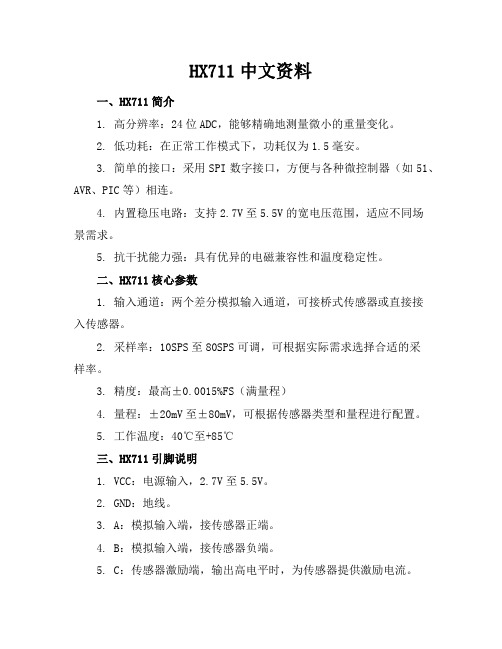
HX711中文资料一、HX711简介1. 高分辨率:24位ADC,能够精确地测量微小的重量变化。
2. 低功耗:在正常工作模式下,功耗仅为1.5毫安。
3. 简单的接口:采用SPI数字接口,方便与各种微控制器(如51、AVR、PIC等)相连。
4. 内置稳压电路:支持2.7V至5.5V的宽电压范围,适应不同场景需求。
5. 抗干扰能力强:具有优异的电磁兼容性和温度稳定性。
二、HX711核心参数1. 输入通道:两个差分模拟输入通道,可接桥式传感器或直接接入传感器。
2. 采样率:10SPS至80SPS可调,可根据实际需求选择合适的采样率。
3. 精度:最高±0.0015%FS(满量程)4. 量程:±20mV至±80mV,可根据传感器类型和量程进行配置。
5. 工作温度:40℃至+85℃三、HX711引脚说明1. VCC:电源输入,2.7V至5.5V。
2. GND:地线。
3. A:模拟输入端,接传感器正端。
4. B:模拟输入端,接传感器负端。
5. C:传感器激励端,输出高电平时,为传感器提供激励电流。
6. D:传感器激励端,输出低电平时,为传感器提供激励电流。
7. E:数字输出端,用于接收外部时钟信号。
8. PD_SCK:串行时钟输入,用于控制AD转换和数据输出。
9. DOUT:串行数据输出,输出AD转换结果。
10. GN:增益选择端,接VCC时为128倍增益,接GND时为64倍增益。
四、HX711应用电路1. 电源电路:为HX711提供稳定的电源输入,确保其正常工作。
2. 传感器接口:将传感器与HX711的A、B、C、D引脚相连,实现信号输入。
3. 微控制器接口:通过SPI接口将HX711与微控制器相连,实现数据传输和控制。
4. 去耦电路:在电源输入端加入滤波电容,提高电路的抗干扰能力。
五、HX711编程基础1. 初始化设置将PD_SCK引脚设置为高电平,确保HX711处于待机状态。
敏察技术有限公司产品说明书:5011型号双面磁制温感器

5011 | SERIES1/2” DISC, HERMETICALLY SEALED THERMOSTATSPECIFICATIONSDesigned to meet demanding shock and vibration requirements, the 5011 series thermostat is a RoHS compliant, positive snap action, single pole / single throw, hermetically sealed unit. Normally supplied with a grounded case construction, an additional terminal can be provided on the case for a positive ground lead or as an isolated device when the unit is insulated from ground.The 5011 series can be used for temperature warning or protection. Calibration is factory set and is tamperproof.FeaturesApplicationsIntroduction• Hermetic glass seal• Ideal for surface and immersion sensing• Multiple mounting and terminations available • Case isolated and case grounded versions• Printed circuit board protections• Air or water cooled engines and transmissions• Fluid sensingContact Ratings Cycles Voltage 100,000120100,000120100,00032Contact Operations Operating Temperature Either close on rise (make) or open on rise (break), SPST (Single Pole, Single Throw)+140ºF to 480ºF (+60ºC to 249ºC)CONTACT OPERATIONTERMINAL SELECTIONMNPZSame as terminal selection “L”Except 2 Leads48.00 ± 1.00(1219.20 ± 25.40)See note 1 for lead specificationsSpecialRequirements Customer to SpecifySame as terminal selection “L”Except 2 Leads24.00 ± 1.00(609.60 ± 25.40)See note 1 for lead specificationsSame as terminal selection “L”Except 2 Leads12.00 ± 1.00(304.80 ± 25.40)See note 1 for lead specificationsQuick Connect Terminal,Grounded Case Only2 Pan Head Screw Terminals, #8-32Isolated Case Only2 QC Terminals, Isolated Case Only2 Leads, Isolated Case OnlySee note 1 for lead specificationsKJDALPan Head Screw Terminal, #8-32Grounded Case OnlyTEMPERATURE CODES AND TOLERANCENote• The standard tolerance for the top temperature is based on the temperature range the top temperature falls in, please refer to the temperature setting chart, and select the appropriate code for a standard top temperature tolerance• For bottom temperature tolerance a “Y” = minimum trip, which indicates the “reset” trip occurs at or above the lower temperature set point.Note• Select any temperature in the range of 140°F to 480°F. Standard choices fall on the 5°F increments, for example 140°F, 145°F, 150°F, 155° F... up to 475°F or 480°F • Specify the °F temperature in the part numbering scheme as a three digit code without the ‘°F’ in the part numbe r. For example, for 200°F, put in code ‘200’• Bottom Temperature in °F” equals the “Top Temperature in °F” minus “Nominal Differential in °F”. For example 310°F - 30°F = 280°FMOUNTING AND ENCLOSURE SELECTION1. The standard lead wire (materials) for different temperature ranges are as follows:A. Up to 220°F (104.4°C) = # 18 AWG standed. UL Style 1015/CSA approved. (PVC insulation, color black)B. 221°F to 350°F (105°C to 176.6°C) = #18 AWG stranded. UL Style 1199/CSA approved. (Teflon® TFE insulation, color black)C. 351°F (177.2°C) and above = #18 AWG stranded. UL style 5288/CSA approved. (Composite of Teflon®, ceramic + glass braid, color brown)2. For mounting code “C” only, encapsulation above the hex is omitted and terminal height is reduced by the amount of encapsulation.3. The marking information on each thermostat will include either the name Sensata, contact operation (CLR) close on rise, (OPR) open on rise, top temperature and date code.*If you require either of the terminal selections “RR” or “SS”, it will require the use of both position 3 (terminal selection). and position 4 (mounting and enclosure selection) in your part number building code. For example: C11RR285C-250Y0.250 ± .0200.687 ± .020(17.45 ± .51)DIA(3.56 )DIAGrounded Case Only+ 0.13– 0.00(.140 )+ 0.05– 0.00(4.75)by (.187)(6.35)(.250)(4.75)TYP .187Isolated or Grounded CaseREF 0.356(9.04)RADDIACEFGSS *RR *HAmericas+1 (888) 438 2214 *******************Europe, Middle East & Africa +359 (2) 804 7165*******************************Asia Pacific*************************.com China +86 (21) 2306 1500Japan +81 (45) 277 7117Korea +82-10-9218-1179 India +91 (80) 67920890Rest of Asia +886 (2) 27602006 ext 2808Page 4CONTACT USSensata Technologies, Inc. (“Sensata”) data sheets are solely intended to assist designers (“Buyers”) who are developing systems that incorporate Sensata products (also referred to herein as “components”). Buyer understands and agrees that Buyer remains responsible for using its independent analysis, evaluation and judgment in designing Buyer’s systems and products. Sensata data sheets have been created using standard laboratory conditions and engineering practices. Sensata has not conducted any testing other than that specifically described in the published documentation for a particular data sheet. Sensata may make corrections, enhancements, improvements and other changes to its data sheets or components without notice.Buyers are authorized to use Sensata data sheets with the Sensata component(s) identified in each particular data sheet. HOWEVER, NO OTHER LICENSE, EXPRESS OR IMPLIED, BY ESTOPPEL OR OTHERWISE TO ANY OTHER SENSATA INTELLECTUAL PROPERTY RIGHT, AND NO LICENSE TO ANY THIRD PARTY TECHNOLOGY OR INTELLECTUAL PROPERTY RIGHT, IS GRANTED HEREIN. SENSATA DATA SHEETS ARE PROVIDED “AS IS”. SENSATA MAKES NO WARRANTIES OR REPRESENTATIONS WITH REGARD TO THE DATA SHEETS OR USE OF THE DATA SHEETS, EXPRESS, IMPLIED OR STATUTORY, INCLUDING ACCURACY OR COMPLETENESS. SENSATA DISCLAIMS ANY WARRANTY OF TITLE AND ANY IMPLIED WARRANTIES OF MERCHANTABILITY, FITNESS FOR A PARTICULAR PURPOSE, QUIET ENJOYMENT, QUIET POSSESSION, AND NON-INFRINGEMENT OF ANY THIRD PARTY INTELLECTUAL PROPERTY RIGHTS WITH REGARD TO SENSATA DATA SHEETS OR USE THEREOF.All products are sold subject to Sensata’s terms and conditions of sale supplied at SENSATA ASSUMES NO LIABILITY FOR APPLICATIONS ASSISTANCE OR THE DESIGN OF BUYERS’ PRODUCTS. BUYER ACKNOWLEDGES AND AGREES THAT IT IS SOLELY RESPONSIBLE FOR COMPLIANCE WITH ALL LEGAL, REGULATORY AND SAFETY-RELATED REQUIREMENTS CONCERNING ITS PRODUCTS, ORDERING OPTIONSA, C, N, YSee Temperature Codes and Tolerance TableClose contacts on temperature rise, 5011 series, grounded case 8-32” screw terminal, mounting bracket with two 0.187” x 0.250” mounting slots, 285°F top temperature with a ±10°F standard top tolerance and a standard 35°F differential between top and bottom temperature for temperature range of 251°F to 400°F, differential helps calculate a bottom temperature of 250°F with a standard minimum reset for contacts to close at or above the bottom temperature set point.WARNINGSRISK OF MATERIAL DAMAGE AND HOT ENCLOSURE• The product’s side panels may be hot, allow the product to cool before touching • Follow proper mounting instructions including torque values • Do not allow liquids or foreign objects to enter this productFailure to follow these instructions can result in serious injury, or equipment damage.HAZARD OF ELECTRIC SHOCK, EXPLOSION OR ARC FLASH• Disconnect all power before installing or working with this equipment • Verify all connections and replace all covers before turning on powerFailure to follow these instructions will result in death or serious injury。
SHARP LB-1085 说明书

2
商标
·HDMI、HDMI 徽标及 High-Definition Multimedia Interface( 高清晰多媒体接口 ) 是 HDMI Licensing LLC 公司的注册商标。
3
亲爱的夏普用户
感谢您购买夏普液晶监视器。为确保产品能长期安全无障碍地运行,请在使用本产品前仔细阅读重要安全说 明。
重要安全说明
电有很多用途,但如果处理不当,也会导致人身伤害和财产损失。本产品是按最高安全标准设计制造的。然而, 不正确地使用也会导致触电或 / 和火灾。为防止潜在危险,请在安装、使用和清洁本产品时仔细阅读下列说明。 为确保您的安全并延长液晶监视器的使用寿命,请在使用产品前仔细阅读下列须知。
1) 阅读这些说明。 2) 妥善存放这些说明。 3) 留意所有的警告。 4) 遵守所有的说明。 5) 不要在水附近使用本设备。 6) 只能使用干布进行清洁。 7) 请勿阻塞散热孔。遵照制造商的说明进行安装。 8) 请勿在任何热源附近安装本产品,如散热器、加热器、火炉或其它发热设备 ( 包括扩音器 )。 9) 请勿拆除两极或接地插头的安全装置。两极插头有两个不同宽度的插塞接头。接地插头有两个插塞接头和一
汞 (Hg)
镉 (Cd)
六价铬 (Cr(VI))
多溴联苯 (PBB)
多溴二苯醚 (PBDE)
印刷电路板
×
○
○
○
○
○
监视器
×
×
○
○
○
○
箱体、底盘
○
○
○
○
○
○
电源
×
○
○
○
○
○
电缆类
○
○
○
○
- 1、下载文档前请自行甄别文档内容的完整性,平台不提供额外的编辑、内容补充、找答案等附加服务。
- 2、"仅部分预览"的文档,不可在线预览部分如存在完整性等问题,可反馈申请退款(可完整预览的文档不适用该条件!)。
- 3、如文档侵犯您的权益,请联系客服反馈,我们会尽快为您处理(人工客服工作时间:9:00-18:30)。
VGS = 0V, TJ = 125°C VGS = -20V VGS = 20V
VGS = -12V, ID = -2.8A VDS = -50V
— 20 — 24 — 32 ns
VDD = -50V, ID = -2.8A, VGS = -12V, RG = 7.5Ω
— 90
6.1 — nH Measured from the center of
drain pad to center of source pad
Ciss Coss Crss
Input Capacitance Output Capacitance Reverse Transfer Capacitance
trr Reverse Recovery Time
— — 138 nS Tj = 25°C, IF = -2.8A, di/dt ≤ 100A/µs
QRR Reverse Recovery Charge
— — 555 nC
VDD ≤ -50V Ã
ton Forward Turn-On Time
Intrinsic turn-on time is negligible. Turn-on speed is substantially controlled by LS + LD.
— -100 — — 100 —
-100 nA 100
IDSS
Zero Gate Voltage Drain Current
RDS(on) Static Drain-to-Source Ã
—
-10 —
-10 µA
— 0.916 — 0.936 Ω
On-State Resistance (TO-39)
— -4.0 V
Ω
— — S( )
— —
-10 -25
µA
— -100 — 100 nA — 11 — 3.0 nC — 4.2
VGS = -12V, ID = -2.8A Ã VGS = -12V, ID = -1.8A VDS = VGS, ID = -1.0mA VDS > -15V, IDS = -1.8A Ã
IS Continuous Source Current (Body Diode) ISM Pulse Source Current (Body Diode) À
— —
— —
-2.8 -11.2
A
VSD Diode Forward Voltage
— — -5.0 V
Tj = 25°C, IS = -2.8A, VGS = 0V Ã
PD @ TC = 25°C
Max. Power Dissipation
Linear Derating Factor
VGS EAS IAR EAR dv/dt
Gate-to-Source Voltage Single Pulse Avalanche Energy Á Avalanche Current À Repetitive Avalanche Energy À Peak Diode Recovery dv/dt Â
— 377 — — 102 — pF — 7.0 —
VGS = 0V, VDS = -25V f = 1.0MHz
Source-Drain Diode Ratings and Characteristics (Per Die)
Parameter
Min Typ Max Units
Test Conditions
Note: Corresponding Spice and Saber models are available on International Rectifier Website. For footnotes refer to the last page
2
元器件交易网
Pre-Irradiation
IRHQ597110
International Rectifier Radiation Hardened MOSFETs are tested to verify their radiation hardness capability. The hardness assurance program at International Rectifier is comprised of two radiation environments. Every manufacturing lot is tested for total ionizing dose (per notes 5 and 6) using the TO-3 package. Both pre- and post-irradiation performance are tested and specified using the same drive circuitry and test conditions in order to provide a direct comparison.
Min -100 —
— — -2.0 1.9 — —
— — — — — — — — — —
Typ Max Units
Test Conditions
——
V
VGS = 0V, ID = -1.0mA
-0.13 — V/°C Reference to 25°C, ID = -1.0mA
— 1.2 Ω
— 0.96
IRHQ597110
Pre-Irradiation
Electrical Characteristics @ Tj = 25°C (Unless Otherwise Specified) (Per Die)
Parameter
BVDSS
Drain-to-Source Breakdown Voltage
∆BVDSS/∆TJ Temperature Coefficient of Breakdown Voltage
Absolute Maximum Ratings (Per Die)
Parameter
ID @ VGS = -12V, TC = 25°C Continuous Drain Current
ID @ VGS = -12V, TC = 100°C Continuous Drain Current
IDM
Pulsed Drain Current À
Pre-Irradiation
-2.8 -1.8 -11.2 12 0.1 ±20 70 -2.8 1.2 -7.1 -55 to 150
Units
A
W W/°C
V mJ A mJ V/ns
oC
300 (for 5s)
0.89 (Typical)
g
1
05/18/05
元器件交易网
combination of low RDS(on) and low gate charge reduces the power losses in switching applications such as DC to DC converters and motor control. These devices retain all of the well established advantages of MOSFETs such as voltage control, fast switching, ease of paralleling and temperature stability of electrical parameters.
Thermal Resistance (Per Die)
Parameter
RthJC RthJA
Junction-to-Case Junction-to-Ambient
Min Typ Max Units — — 11.8
°C/W — — 60
Test Conditions Typical socket mount
TJ TSTG
Operating Junction Storage Temperature Range Pckg. Mounting Surface Temp. Weight
For footnotes refer to the last page
IRHQ597110
100V, Quad P-CHANNEL
RDS(on) Static Drain-to-Source Ã
— 0.96
— 0.98 Ω
On-State Resistance (LCC-28)
VSD
Diode Forward Voltage Ã
ID -2.8A -2.8A
International Rectifier’s RAD-HardTM HEXFET® MOSFET Technology provides high performance power MOSFETs for space applications. This technology has over a decade of proven performance and reliability in satellite applications. These devices have been characterized for both Total Dose and Single Event Effects (SEE). The
RAD-Hard™ HEXFET®
5 TECHNOLOGY
LCC-28
Features:
n Single Event Effect (SEE) Hardened n Low RDS(on) n Low Total Gate Charge n Proton Tolerant n Simple Drive Requirements n Ease of Paralleling n Hermetically Sealed n Ceramic Package n Surface Mount n Light Weight