ASC-MS24使用说明书
OSS24智能自适应人流传感器壁开关说明书
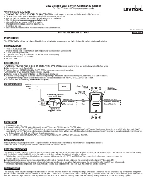
WARNINGS AND CAUTIONS• TO AVOID FIRE, SHOCK, OR DEATH: TURN OFF POWER at circuit breaker or fuse and test that power is off before wiring!• To be installed and/or used in accordance with electrical codes and regulations.• Confirm that device ratings are suitable for application prior to installation.• Use this device with copper or copper clad wire only .• Connect to field wiring rated for 60° C or greater.• DO NOT install if product appears to be damaged.• For indoor use only.•Read these instructions before installation and retain for future reference.The OSS24 Wall Switch is a low voltage (24V) intelligent self-adapting occupancy sensor that is designed to replace existing wall switches.DESCRIPTION• 1000 sq. ft. coverage area• Passive Infrared (PIR) sensor with dual-element pyrometer and 12-element cylindrical lens • 24VDC (requires power pack)• Adjustable Time Delay: 4-30 minutes; self-adjusts based on occupancy • Light Level Adjustment: 10 to 500FC •UL, cUL ListedSPECIFICATIONSINSTALLATION1.WARNING: TO AVOID FIRE, SHOCK, OR DEATH: TURN OFF POWER at circuit breaker or fuse and test that power is off before wiring!2.Remove the old switch if applicable.3.Wire as shown in WIRING DIAGRAM. NOTE: OSS24 requires one power pack per output.4.Install sensor in wall box using mounting screws provided.5.Restore power to the sensor and allow it to initialize (up to 2 minutes).6.Sensor is factory configured to provide the most energy savings. If additional adjustments are required, see the ADJUSTMENTS section.7.If daylight harvesting is desired, calibrate the sensor’s photocell as described in the PHOTOCELL CONTROL section.8.Install wall plate (not included). Installation is complete .TEST MODE1.Ensure lights are ON.2.Press and hold the ON/OFF button. Lights will cycle OFF then back ON. Release the ON/OFF button.3.Sensor is now in Test Mode (NOTE: While in Test Mode the sensor will operate in Automatic ON/Automatic OFF mode). Vacate room; lights should turn OFF after 5 seconds. Wait 5 seconds after turn OFF before re-entering space. Step back into room, lights will turn back ON. Repeat walk test as necessary to confirm sensor is operating and detecting in the area as desired. Sensor will flash red LED when detecting occupancy.4.To exit Test Mode, press any button (NOTE: Sensor will automatically exit Test Mode after sixty (60) minutes).MANUAL OVERRIDEPress button(s) to toggle lights ON or OFF. Lights will remain in the last state determined by the buttons while occupancy is detected.Sensor will return to the programmed mode of operation when the sensor times out.ADJUSTMENTSThe following switch adjustments require that the sensor’s cover be removed. Remove the cover by inserting a small blade screwdriver into the catch at the top of the sensor and gently pry the cover off. Set the adjustment switches as desired (see CONFIGURATION SWITCH SETTINGS section). Factory default is all switches OFF. To re-install cover, place cover directly over the sensor and align the cover’s four (4) catches with the recesses in the sensor housing. Snap cover onto housing making sure that all catches are securely in place.PHOTOCELL CONTROLThe photocell is used to detect if other light sources such as sunlight, are sufficient to illuminate the space without turning on the controlled lights. The sensor is shipped from the factory with the photocell control disabled. If use of the photocell is desired, calibrate the photocell set point as follows:1.With the light level at the desired level where the controlled lights should be off, PRESS and RELEASE the photocell set button using the end of a paper clip or small bladed screwdriver.2.Step back from the sensor to avoid changing ambient light levels in the room. During calibration the sensor will turn the lights OFF then back ON.3.After the calibration process, the sensor will return to its programmed mode of operation. During occupancy, the sensor will turn lighting OFF sixty (60) seconds after reaching or exceeding the set point level. When the lighting level drops below the set point level the sensor will turn the lights ON.DI-000-OSS24-05ALow Voltage Wall Switch Occupancy SensorCat. No. OSS24 - 24VDC (requires power pack)WIRING DIAGRAMGround Neutral LineDI-000-OSS24-05A© 2016 Leviton Mfg. Co., Inc.Switch 1 - Relay 1 Sensor OperationPrograms the sensor for either Manual ON/Automatic OFF operation or Automatic ON/Automatic OFF operation. When set to Manual ON/Automatic OFF mode, lights are turned ON by manually pressing the ON/OFF button. If the sensor times out and turns the lights OFF in the Manual ON/Automatic OFF mode while the space is still occupied, any motion detected within thirty (30) seconds will automatically turn the lights back ON, without requiring the user to press the ON button.Switch 2 - NOTE: Switch 2 has no function on single relay models.Switch 3 - Adaptive or Fixed TimerControls selection between Adaptive Timer Mode and Fixed Timer Mode. In Adaptive Timer Mode, the sensor automatically self-adjusts its timeout delay to optimize energy savings. The sensor will initialize its timer value to eight (8) minutes. If the Bank B Timer Select 0 and Timer Select 1 switches have been set to four (4) minutes, this will be the smallest timer value used. In Fixed Timer Mode, the sensor’s self-adapting timer functions are disabled and the sensor’s timeout delay is set according to the Bank B Timer Select 0 and Timer Select 1 switch settings.Switch 4 - Adaptive ResetThe sensor is equipped with self-adaptive technology which automatically adjusts the sensor’s sensitivity and timer settings to optimize performance based on occupancy patterns. The sensor constantly learns and adjusts appropriately. If the learned settings need to be reset (e.g. when relocating sensor to another area), toggle the switch ON then OFF. The adaptive timer is reset according to the Bank B Timer Select 0 and Timer Select 1 switches. The adaptive sensitivity is reset to factory default. The photocell sensor settings are also reset to factory default (disabled) such that the sensor will turn on the light(s) in response to occupancy regardless of ambient light levels in the lighted space. (NOTE: Adaptive reset can also be achieved by pressing and holding the photocell set button for ten (10) seconds).Switch 5 – Relay BypassIf it is necessary to service the controlled circuits without de-energizing them at the breaker panel (NOTE: this is not recommended as a standard procedure), perform the following steps:1. With the lights ON, set the relay bypass switch to the ON position.2. Push the button(s) to turn the lights OFF.3. Push the button(s) again to verify override (lights should not come back on).The relay bypass switch will now interrupt sensor operation, preventing output(s) from turning ON again, regardless of occupancy or pushbutton conditions. To return the sensor to normal operation, flip the relay bypass switch to the OFF position. To confirm sensor is operating normally, lights should now turn ON and OFF when the button(s) are pressed.Switches 1 and 2 – Timer SettingsSets the length of time lights will remain ON after last motion is detected. The timeout value can be set to 4, 8, 16 or 30 minutes.See Bank A – Switch 3 - Adaptive or Fixed Timer section for additional information.Switches 3 and 4 - Sensing Technology Enable/DisableEnables or disables the occupancy sensing technologies used by the sensor. If all sensing technologies are disabled, sensor operates as a manual ON/OFF switch.Switch 5 - SensitivitySets the sensor’s initial Passive Infrared (PIR) sensitivity level. Sensitivity can be set to either High or Low.For Technical Assistance Call: 1-800-824-3005 (U.S.A. Only) LIMITED 5 YEAR WARRANTY AND EXCLUSIONSLeviton warrants to the original consumer purchaser and not for the benefit of anyone else that this product at the time of its sale by Leviton is free of defects in materials and workmanship under normal and proper use for five years from the purchase date. Leviton’s only obligation is to correct such defects by repair or replacement, at its option. For details visit or call 1-800-824-3005. This warranty excludes and there is disclaimed liability for labor for removal of this product or reinstallation. This warranty is void if this product is installed improperly or in an improper environment, overloaded, misused, opened, abused, or altered in any manner, or is not used under normal operating conditions or not in accordance with any labels or instructions. There are no other or implied warranties of any kind, including merchantability and fitness for a particular purpose , but if any implied warranty is required by the applicable jurisdiction, the duration of any such implied warranty, including merchantability and fitness for a particular purpose, is limited to five years. Leviton is not liable for incidental, indirect, special, or consequential damages, including without limitation, damage to, or loss of use of, any equipment, lost sales or profits or delay or failure to perform this warranty obligation . The remedies provided herein are the exclusive remedies under this warranty, whether based on contract, tort or otherwise.FOR CANADA ONLYFor warranty information and/or product returns, residents of Canada should contact Leviton in writing at Leviton Manufacturing of Canada Ltd to the attention of the Quality Assurance Department, 165 Hymus Blvd, Pointe-Claire (Quebec), Canada H9R 1E9 or by telephone at 1 800 405-5320.* Only functional on multi-tech models.。
安浦鸣志步进伺服SSM24S-Q手册

法国真空计-ACS控制器

设置点使用,耦合装置的隔离和继电器变得无效,因此建议使用外接电源。
七 技术参数
主要规格 环境 适用真空计
电压 频率 功耗 重量 超电压类别 防护等级 存储温度 运行温度 相对湿度 使用 污染程度 防护等级 真空计数量 真空计类型
100 - 240VAC
50∕60Hz
<50VA
1.3kg 类别Ⅱ Note1 等级Ⅰ装置 Note2 -20~+60℃ Note3 +5~+50℃ <70% 仅用于室内 最高海拔 2000m 污染程度Ⅱ Note4 IP30 Note5
作为一个 EMC 测量,外部连接使用带屏蔽的电线。屏蔽必须 在另一端设备处接地。忽视可导致干扰造成的错误或设备损 坏。 当使用继电器输出接点时,接点容量必须在 125VAC,0.3A 或 小于 30VDC,1A。忽视可导致干扰造成的错误或设备损坏。
24VDC 电源仅用于远程控制或继电器输出时的压力信号输 出,与高阻抗设备连接并使用小电流。始终使用 0.1A 以下电 源。忽视可导致设备损坏。
备注:必须进行正确的接地,否则容易造成电击
4 打开电源开关.
四 控制器显示
1 控制器自我测试
2 显示控制器版本
3 显示真空计型号
如果连接 AP2004 会显示”AP”(图示 AHC 为另一型号真空计) 4 显示真空计所测之处的真空度(如果真空计连接正确)
TELLIS-24

TELLIS-24 RADIO REMOTE COTROLSYSTEM OPERATION MANUAL抚顺铝厂出铝设备无线遥控系统操作手册Grand Industrial Group Company Ltd.CANADA录1安全提示 (4)2系统概述 (5)2.1 RC2012A手持遥控器(发射机) (6)2.2 BD2124接收驱动装置 (6)2.3 RBD2124系统 (6)3RC2012A手持遥控器(发射机) (6)3.1 RC2012A的控制元件 (6)3.2 操作信息 (7)4BD2124 接收驱动装置 (8)4.1 BD2124的控制输出 (8)4.2 操作信息 (10)4.3 供电电源 (12)5系统安装 (12)5.1 RC2012A电池的安装 (12)5.2 BD2124接收驱动装置的安装 (13)5.3 BD2124接收驱动装置的接线 (13)5.4 BD2124电源连接 (14)5.5 典型电源及输出接线 (14)6系统操作 (15)6.1 安全操作 (15)6.2 RC2012A手持遥控器的使用 (15)6.3 操作信息 (17)7故障诊断和排除 (17)8维护和保养 (18)9技术指标 (19)10相关标准 (20)此页为空白1 安全提示使用前请仔细阅读以下安全提示注意:未经许可,任何非指定的人员对设备进行改动或修改都有可能造成该遥控系统和所控设备无法工作!如果不严格遵守此安全警告有可能导致所遥控设备和本系统的非正常运行,并可能造成人员伤亡!安装1.提供安全电源开关:设备维修时该装置必须与主电源断开。
2.使用正确的导线接线:松动或破损的导线有可能导致系统失灵、操作中断、设备损坏、或带来人身安全隐患。
3.不要在高温环境下安装:温度超过摄氏70度下安装有可能损坏设备。
操作人员安全须知1. 开机操作前,操作人员必须确认所控设备周围无障碍,并选择好自己做站位置可以全方位观察到所要控制的设备。
液相色谱质谱联用仪使用说明书
液相色谱质谱联用仪使用说明书1. 产品概述液相色谱质谱联用仪(Liquid Chromatography Mass Spectrometry,LC-MS)是一种高效且准确的分析仪器,常用于生物医药、环境监测、食品安全等领域。
本说明书旨在向用户介绍该仪器的基本使用方法和注意事项,以帮助用户顺利操作和获取准确的分析结果。
2. 仪器部件及参数2.1 液相色谱部分(此部分根据具体仪器的配置进行介绍,包括进样器、色谱柱、流动相体系等,具体参数包括但不限于:进样方式、柱温、流速范围、浓度范围等)2.2 质谱部分(此部分根据具体仪器的配置进行介绍,包括离子源、激发源、质谱分析器等,具体参数包括但不限于:扫描方式、离子化方式、质谱范围等)3. 仪器操作步骤3.1 准备工作在使用液相色谱质谱联用仪之前,确保以下准备工作已完成:(1)确认仪器及相关设备已接通电源,并处于正常工作状态;(2)检查流动相及其他试剂的储存量,并进行必要的更换或补充;(3)保证色谱柱处于良好的状态,检查柱温控制装置的工作情况。
3.2 进样设置(此部分根据具体仪器的配置进行介绍,包括进样器的基本设置、进样方式的选择、进样量的确定等)3.3 色谱条件设置(此部分根据具体仪器的配置进行介绍,包括流动相体系的选择、流速的设置、柱温的控制等)3.4 质谱条件设置(此部分根据具体仪器的配置进行介绍,包括离子化方式的选择、质谱范围的设置、激发源的参数调整等)3.5 数据采集和分析(此部分根据具体仪器的配置进行介绍,包括数据采集软件的使用、质谱图的分析、定量分析方法的建立等)4. 注意事项4.1 安全操作(根据仪器的特点和操作需要,提醒用户注意电源使用、化学品的安全储存和处理、仪器的地耐压等事项)4.2 仪器维护与保养(根据仪器的特点和使用需求,介绍仪器的日常维护与保养,如色谱柱的清洗和更换、离子源的清洗等)4.3 故障排除与常见问题解答(根据仪器的特点和常见故障情况,提供故障排除的方法和常见问题的解答。
SM24A 调节器说明书

SM24ADamper actuator for adjusting dampers intechnical building installations• Air damper size up to approx. 4 m²• Torque motor 20 Nm• Nominal voltage AC/DC 24 V• Control Open/close, 3-pointTechnical dataElectrical data Nominal voltage AC/DC 24 VNominal voltage frequency50/60 HzNominal voltage range AC 19.2...28.8 V / DC 19.2...28.8 VPower consumption in operation 2 WPower consumption in rest position0.2 WPower consumption for wire sizing 4 VAConnection supply / control Cable 1 m, 3x 0.75 mm²Parallel operation Yes (note the performance data)Functional data Torque motor20 NmDirection of motion motor selectable with switch 0 (ccw rotation) / 1 (cwrotation)Manual override with push-button, can be lockedAngle of rotation Max. 95°Angle of rotation note can be limited on both sides with adjustablemechanical end stopsRunning time motor150 s / 90°Sound power level, motor45 dB(A)Mechanical interface Universal shaft clamp reversible 10...20 mmPosition indication Mechanical, pluggableSafety data Protection class IEC/EN III, Safety Extra-Low Voltage (SELV)Power source UL Class 2 SupplyDegree of protection IEC/EN IP54Degree of protection NEMA/UL NEMA 2Enclosure UL Enclosure Type 2EMC CE according to 2014/30/EUCertification IEC/EN IEC/EN 60730-1 and IEC/EN 60730-2-14UL Approval cULus according to UL60730-1A, UL60730-2-14and CAN/CSA E60730-1The UL marking on the actuator depends onthe production site, the device is UL-compliantin any caseHygiene test According to VDI 6022 Part 1 / SWKI VA104-01, cleanable and disinfectable, lowemissionType of action Type 1Rated impulse voltage supply / control0.8 kVPollution degree3Safety dataAmbient humidity Max. 95% RH, non-condensing Ambient temperature -30...50°C [-22...122°F]Storage temperature -40...80°C [-40...176°F]Servicingmaintenance-free WeightWeight 0.94 kg•••••••Safety notesThis device has been designed for use in stationary heating, ventilation and air-conditioning systems and must not be used outside the specified field of application, especially in aircraft or in any other airborne means of transport.Outdoor application: only possible in case that no (sea) water, snow, ice, insolation or aggressive gases interfere directly with the device and that it is ensured that the ambient conditions remain within the thresholds according to the data sheet at any time.Only authorised specialists may carry out installation. All applicable legal or institutional installation regulations must be complied with during installation.The device may only be opened at the manufacturer's site. It does not contain any parts that can be replaced or repaired by the user.Cables must not be removed from the device.To calculate the torque required, the specifications supplied by the damper manufacturers concerning the cross-section and the design, as well as the installation situation and the ventilation conditions must be observed.The device contains electrical and electronic components and must not be disposed of as household refuse. All locally valid regulations and requirements must be observed.Product featuresSimple direct mountingSimple direct mounting on the damper shaft with a universal shaft clamp, supplied with an anti-rotation device to prevent the actuator from rotating.Manual overrideManual override with push-button possible (the gear train is disengaged for as long as the button is pressed or remains locked).Adjustable angle of rotation Adjustable angle of rotation with mechanical end stops.High functional reliabilityThe actuator is overload protected, requires no limit switches and automatically stops when the end stop is reached.AccessoriesElectrical accessoriesDescriptionType Auxiliary switch 1x SPDT add-on S1A Auxiliary switch 2x SPDT add-onS2A Feedback potentiometer 140 Ω add-on P140A Feedback potentiometer 1 kΩ add-on P1000A Feedback potentiometer 10 kΩ add-onP10000A Mechanical accessoriesDescriptionType Actuator arm for standard shaft clamp (reversible)AH-20Shaft extension 240 mm ø20 mm for damper shaft ø12...21 mm CrNi AV12-25-I Shaft extension 240 mm ø20 mm for damper shaft ø8...22.7 mm AV8-25Ball joint suitable for damper crank arm KH8KG8Ball joint suitable for damper crank arm KH8 / KH10KG10A Damper crank arm Slot width 8.2 mm, clamping range ø10...18 mm KH8Shaft clamp one-sided, clamping range ø8...26 mm, Multipack 20 pcs.K-ENSA Shaft clamp one-sided, clamping range ø12...26 mm, for CrNi shaft (INOX), Multipack 20 pcs.K-ENSA-IDescription Type Shaft clamp reversible, clamping range ø10...20 mm K-SAAnti-rotation mechanism 180 mm, Multipack 20 pcs.Z-ARS180Anti-rotation mechanism 230 mm, Multipack 20 pcs.Z-ARS230 Form fit insert 10x10 mm, Multipack 20 pcs.ZF10-NSAForm fit insert 12x12 mm, Multipack 20 pcs.ZF12-NSAForm fit insert 15x15 mm, Multipack 20 pcs.ZF15-NSA Form fit insert 16x16 mm, Multipack 20 pcs.ZF16-NSA Mounting kit for linkage operation for flat installation ZG-SMA Position indicator, Multipack 20 pcs.Z-PI Baseplate extension for SM..A to SM../AM../SMD24R Z-SMAWire colours:1 = black2 = red3 = whiteElectrical installationSupply from isolating transformer.Parallel connection of other actuators possible. Observe the performance data.Wiring diagramsAC/DC 24 V, open/closeAC/DC 24 V, 3-point DimensionsSpindle lengthMin. 48Min. 20Clamping rangeWhen using a round shaft made of CrNi(INOX): ø12...20 mm。
定位器说明书msp-24

定位器说明书msp-24※气动连接·使用与定位器气源端口处标识的标准接口连接气源·连接定位器的输出与气动执行器的气缸※电气连接根据下列接线端子图以及设计要求进行相应的配线(一般只需+11,-12,+31,-32)※调试步骤1. 接通气源,检查减压阀后压力是否符合执行器的铭牌参数要求(定位器的最大供气压力为7Bar,但实际供气压力必须参考执行器所容许的最大气源压力);2. 接通4---20mA输入信号。
(定位器的工作电源取自输入信号,由DCS二线制供电,端电压为DC8.7V左右,不能将DC24V直接加至定位器,否则有可能损坏定位器电路);3. 检查位置反馈杆的安装角度(如定位器与执行器整体供货,则由执行器供货商安装调试完毕,只需作检查确认,该步并非必须):·按住MODE键·同时点击↑或↓键,直到操作模式代码1.3显示出来·松开MODE键。
·使用↑或↓键操作,使执行器分别运行到两个终端位置,记录两终端角度。
·两个角度应符合下列推荐角度范围(最小角位移20度;无需严格对称)直行程(小角度)应用在-28°---+28°之内。
角行程(大角度)应用在-57°---+57°之内。
全行程角度应不小于25°4. 启动自动调整程序方法一·按住MODE键·同时点击↑或↓键,直到操作模式代码1.1显示出来根据变换角度不同,分别选择MODE键或ENTER键进行自动整定;直行程(小角度):·按住MODE键直到显示ADJ-LIN,然后松开该键,·再按住MODE键3秒直到计数器倒数到0,·松开MODE键,自动调整程序开始运行(显示正在进行的程序语句号)。
·自动调整程序顺利结束后,系统参数会被自动存储。
角行程(大角度):·按住ENTER键直到显示ADJ-ROT,然后松开该键,·再按住ENTER键3秒直到计数器倒数到0,·松开ENTER键,自动调整程序开始运行(显示正在进行的程序语句号)。
卡洛瓦瑟控制系统SH2WEB24产品说明书

SH2WEB24Central unit moduleThe SH2WEB24 is a programmable integrated unit specially designed for home and building automation applications.The controller includes dedicated functions for home automation such as light control (DALI), temperature control, roller blind control, alarm monitoring, energy monitoring, etc....The SH2WEB24 is as default configured without intelligent in- and output functions to run modules on the smart Dupline bus.In order to set up the intelligent functions, the SH2WEB24 has to be configured by the Windows based configuration software.This software is free downloadable from Carlo Gavazzi website.Benefits• Configurable by software. Home and building automation functions and energy data logging are configurable by software.• Spread sheets compatible. All data exports are compatible with Excel or other spread sheets.• Modularity. The system is composed by modules so that each installation can be precisely and easily sized.• Scalability.New modules can be progressively integrated into the system according to the application needs.• Fast and easy pletely free topology, no special cable required, no screen or twist. It can go for 2 km and even further with repeaters.• Remote control. All functions can be remotely controlled while the owner is away and moreover a series of actions can be automatically performed.• User-friendly. The system is user-friendly and really anyone can easily learn to master it.ApplicationsSmart Dupline®is a bus system that offers unique solutions for a wide range of applications in home and building automation, industrial automation, water distribution, energy management, railway systems and many other areas.Main features• Micro PC with Web-server• Linux embedded operating system• Two RS485 communication ports (Modbus)• One Ethernet port• Two multi purpose USB 2.0 ports • Data logging•Internal data storage up to 30 years in a 4GB memoryStructureFeaturesGeneralEnvironmentalCompatibility and conformityPower SupplyInputs/outputs insulation• 0kV: inputs / outputs are not insulated.• 2kVrms: EN61010-1, IEC60664-1 - over-voltage category III, pollution degree 2, double insulation on systems with max. 300Vrms to ground.• 0.5kVrms: the insulation is functional type Mounting.Main hardware characteristicsHS BusAuxiliary Internal BusMain functionsPortsEthernetRS485USBMicro SD slotMini-USBNote*: this requires a specific driver be installed in the PC. The driver is downloadable from Carlo Gavazzi website.Communication protocolsIntroductionThe Sx2WEB module collects data from the field, it process collected data and communicates to remote systems. Different TCP/IP based communication protocols can be used. All protocols are supported by wired and wireless connection and managed on both local network (LAN) and remote one (WAN).Protocol overviewInbound TCP/IP communicationOutbound TCP/IP communicationModbus TCP communicationConnection to the configuration toolConnection DiagramsFig. 1 Power supplyReferencesFurther readingOrder codeSH2WEB24CARLO GAVAZZI compatible componentsCOPYRIGHT ©2015Content subject to change. Download the PDF: 。
- 1、下载文档前请自行甄别文档内容的完整性,平台不提供额外的编辑、内容补充、找答案等附加服务。
- 2、"仅部分预览"的文档,不可在线预览部分如存在完整性等问题,可反馈申请退款(可完整预览的文档不适用该条件!)。
- 3、如文档侵犯您的权益,请联系客服反馈,我们会尽快为您处理(人工客服工作时间:9:00-18:30)。
安森读卡器 黑色 红色 绿色 白色 灰色
线序 GND +12V DATA0 DATA1 BUZZER
安森控制器 RDRD+ D0 D1 BUZ
注:本控制器可以设置成双门双 向读卡或四门单向读卡,具体 接口定义请参考图1/图2。
3.控制器接口定义
地址及波 特率设置
报警输入
出 门 按 钮/门 磁 输 入 出 门 按 钮/门 磁 输 入
TX RX
485通迅 门1控制端口
门2控 制 端 口
报警输出端口 报警输出端口 电源接口
485
2312
LED1 LED2 LED3 LED4 LED5 LED6 LED7 LED8
8位 拨 码 盘
ON
DI P
12345678
ASC-MS24
双门双向接线图
POWER
RD_OK
复位开关/通迅 密码清空开关
ON
DIP
12345678
通过拔码开关更改控制器的识别地址(出厂地址为0),控制器地址设置如下: 注:每条总线上可以接128个控制器,每个控制器的地址一定要是唯一的。
ON
DIP
12345678
地址0
ON
DIP
12345678
地址6
ON
DIP
12345678
地址12
ON
DIP
12345678
地址18
ON
R S 4 8 5转 换 器
计算机接口
12345
54321
DB9Pin母头
DB9Pin公头
本图报警输出都为 常开接法,您可以 选择常闭方式。
控制器指示灯说明: LED1:门锁控制指示灯1 LED2:门磁报警指示灯1 LED3:门锁控制指示灯2 LED4:门磁报警指示灯2 LED5:自由报警指示灯1 LED6:自由报警指示灯2 LED7:自由报警指示灯3 LED8:自由报警指示灯4 POWER:电源指示灯 Rd_OK:测试读卡正常指示灯 RX\TX:485通信指示灯
2.1、不要在任何元器件以及控制器带电时对其连接与操作。 2.2、务必使用说明书指定的方法连接系统。 2.3、使用专用电源。 2.4、控制器只能直接使用RS232或RS485中的一种方式与计算机通讯,
因此务必对JP1进行正确的跳接。 2.5、改变通讯方式时,跳线帽不能横向跳接。
232 485 232 485 232 485 232 485
报警输入
出门按钮/门磁输入 出门按钮/门磁输入
读卡器接口
读卡器接口
ALR4 GND ALR3 ALR2 GND ALR1 D_S4 GND AN4 D_S3 GND AN3 D_S2 GND AN2 D_S1 GND AN1 4BUZ 4RD1 4RD0 RD+ RD3BUZ 3RD1 3RD0 2BUZ 2RD1 2RD0 RD+ RD1BUZ 1RD1 1RD0
4.更改通讯方式
通过跳接JP1的跳线帽更改与计算机的通讯方式;
232 485 232 485
JP1
RS232方式
JP1
RS485方式
485 1 232
8位 拨 码 盘
ON
DIP
12345678
5.更改控制器地址
ON
DIP
485
SW1
1 232
12345678
1~ 7号拔码开关 调整识别地址
8位 拨码盘
DIP
12345678
地址1
ON
DIP
12345678
地址7
ON
DIP
12345678
地址13
ON
DIP
12345678
地址19
ON
DIP
12345678
地址2
ON
DIP
12345678
地址8
ON
DIP
12345678
地址14
ON
DIP
12345678
地址20
ON
DIP
12345678
地址3
ON
DIP
关闭计算机并断开其电源。 1.4、更改控制器的通讯方式(232或485方式)、通讯速率与通讯地址。 1.5、再次确认连接无误。 1.6、打开电源,启动计算机调试。详细的调试方法请参见“工程安装调
试手册”。
2.注意事项
注:M系列控制器只能适配安森Safesmart安保管 理软件。
未能遵循标有此符号的下列事项可能会造成系统无法正常工作、财 产损失甚至人身伤害。
JP1
JP1
JP1
JP1
2.6、以RS485总线方式接入计算机时,一条总线最多接入32个控制器, 同一总线上的控制器的识别地址不能相同。
磁力锁1
R
ASV-232/485
门禁控制器接线图
上电闭锁接法
V+
V-
警灯
NO
COM
NC
警号
485+ 485GND 1C 1NC 1NO 2C 2NC 2NO 3C 3NC 3NO 4C 4NC 4NO 5C 5NC 5NO 6C 6NC 6NO 7C 7NC 7NO 8C 8NC 8NO 12V 12V GND GND
报警输入1
门磁1
红 黑灰白 绿 色 色色色 色
出门按钮1
R
123 456 789
0#
2620
读卡器1
AC 220V 50Hz
AC220V
控制器电源
③③②②①① -B +B GND+12V GND+12V
自由报警 自由报警 自由报警 自由报警
输出1 输出2
输出3 输出4
1C 1NC 1NO 2C 2NC 2NO 3C 3NC 3NO 4C 4NC 4NO
控制器
复位开关/通迅密码清空开关
专业专注 精益求精
12345678
地址9
ON
DIP
12345678
地址15
ON
DIP
12345678
地址21
ON
DIP
12345678
地址4
ON
DIP
12345678
地址10
ON
DIP
12345678
地址16
ON
DIP
12345678
地址22
ON
DIP
12345678
地址5
ON
DIP
12345678
地址11
ON
DIP
读卡器接口
RD_OK
读卡器接口
12345678
DIP
ON
8位 拨 码 盘
RS232通讯接口
485 1 232
232/485转换
485通信指示灯
TX RX
电源接口
报警输出端口
报警输出端口
门2控 制 端 口
485通迅 门1控制端口
485+ 485GND 1C 1NC 1NO 2C 2NC 2NO 3C 3NC 3NO 4C 4NC 4NO 5C 5NC 5NO 6C 6NC 6NO 7C 7NC 7NO 8C 8NC 8NO 12V 12V GND GND
DIP
12345678
地址29
6.更改通讯速率
M系 列 控 制 器 支 持9600bps与1 9200bps两 种 通 讯 速 率 与 计 算 机 通 讯(默 认 设 置 为19200bps),控 制 器 上 设 置 的 波 特 率 一 定 要 和 软 件 上 使 用 串 口 的 波特率一致。
ON
DIP
地址及波 特率设置
RS232通讯接口
232/485转换
485通信指示灯
ON
8位 拨 码 盘
12345678
报警输入4 报警输入3 报警输入2 报警输入1
门磁4 出门按钮4
门磁3 出门按钮3
门磁2 出门按钮2
门磁1 出门按钮1
读卡器4
读卡器3
读卡器2
读卡器1
ALR4 GND ALR3 ALR2 GND ALR1 D_S4 GND AN4 D_S3 GND AN3 D_S2 GND AN2 D_S1 GND AN1
12345678
地址17
ON
DIP
12345678
地址23
ON
DIP
12345678
地址24
ON
DIP
12345678
地址30
ON
DIP
12345678
地址25
ON
DIP
12345678
地址31
ON
DIP
12345678
地址26
ON
DIP
12345678
地址27
ON
DIP
12345678
地址28
ON
报警输入4 报警输入3 报警输入2 报警输入1
空
门磁2 出门按钮2
门磁1 出门按钮1
读卡器4
读卡器3
读卡器2
读卡器1
ALR4 GND ALR3 ALR2 GND ALR1 D_S4 GND AN4 D_S3 GND AN3 D_S2 GND AN2 D_S1 GND AN1
4BUZ 4RD1 4RD0 RD+ RD3BUZ 3RD1 3RD0 2BUZ 2RD1 2RD0 RD+ RD1BUZ 1RD1 1RD0
4BUZ 4RD1 4RD0 RD+ RD3BUZ 3RD1 3RD0 2BUZ 2RD1 2RD0 RD+ RD1BUZ 1RD1 1RD0
RD_OK
读卡器接口
读卡器接口
出 门 按 钮/门 磁 输 入 出 门 按 钮/门 磁 输 入