Ego one功能说明书(带温控_修改20151012)
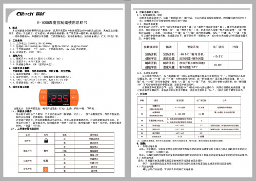
E-1000温控器中文说明书
灯先符号
回
灯先灭
灯光亮
8 . 3 盯先缰 电揭
通过按动灯先按键
亮
•
国
9 出厂参数一键还原
在 锁 定状$下钱佳 " A " 植待盟 10砂 U 上 ,这时E示 "rES"3秒钟在追3秒钟内按"胆锁链/OK " 键, 可 以对温植棉 参盟进行 出广剧认值的恢重 并且示 "YES " , 保存参娘时如果出现错误 温度显示 盲显示 'Er r" , :3秒后进入正常显示状击4 理议 此时温控器重时通 电 h 1 0、接线固
()-- 120 小时
E 小时
化嚣闰lVI ìt时万宝t
割琦回 矗
口.遇电后回咽j帽'积工作时司 l : iM晤后E细帆禀积工悻时司
A
与制凯奸'由制冲开甜'"仨直柑位 与制1A开拍制,噜开蛐 问""甜位
0,5'( : "'1 0'(;
05咽c_,口℃ 1口 'C -lO'C
符号
核态 灭
罪事意义 非锁定状态 注 锁定状态
设定范围 40.0 'C 甸和l 冷 开 机
2.4
存储温度
25'( … 75'C
3、坦幅R寸z
3.1 、 直矶尺寸长85. 0X 商35 , Q X 罩63 , 8 (rrm) 3. 2 、 安装尺 寸长 71 X 宽 29 (m叫
加热固 差串l冷 回 差
加热开机+加热回差+ 制冷回 差 "85"(:
.,.
Aegisone中文说明书使用中文中文说明书A

Aegis one中文说明书祝贺您选择了AE Aegis one音箱这一对使用了金属振膜的强有力的两路分音书架箱请花几分钟阅读本说明书这有利于使音箱获得最佳的表现Aegis one音箱的中低音单元使用了金属振膜技术该项技术在著名的REFERENCE系列已大获成功坚硬的合金振膜可以确保完美活塞运动的实现而且振膜本身可以成为音圈的散热器这些特征可以提供出人意外的清澈感透明度动态范围和功率承受能力Aegis one的高音单元是一只优质的丝膜球顶与其他单元平滑连接所有的单元均经完备的磁屏蔽处理这样您就可以把它放在靠近电视机的位置Aegis one音箱内部接线为优质的OFC线可强化细节和透明度方面的表现Aegis one的最佳摆放高度是当您坐下时耳朵的位置与高音单元平齐或稍低聆听时最好把网罩摘除为充分发挥细节和动态方面的边县音箱需要坚固的支承坚固的脚架包括脚钉脚锥等一系列可靠的支承措施专用的脚架有助于获得良好的声像分离度和纵深感如果Aegis one是放在脚架上的话支承一定要稳固角锥建议放在箱体下方当音箱靠近墙壁时主要对低频产生影响音箱应当远离墙角音箱可以放在离后墙及侧墙相当近的位置但要避免音箱到后墙或侧墙的距离等于音箱离地面的距离需要反复试验才能找到一个能获得丰满而清晰低频的位置相信您的判断和耳朵为获得最佳的声像定位音箱应尽量远离聆听位置在接线时应确保功放处于关机状态否则很容易损坏音箱或功放连接时将音箱的极与功放的极红色用音箱线联接同样地将音箱的极与功放的极黑色联接注意左右音箱分别和功放的左右声道相连接好线后打开功放电源选择相应的节目源并逐渐拧大音量技术指标全频频率38Hz-22kHz响应频率响应 (+/-3dB) 50Hz-20kHz灵敏度 90dB/1w/1m分频点 2.8kHz额定功率 120W重量 7kg箱体尺寸192x362x235mm(WxHxD)。
EPIC 多用途封闭接触器 150A以上电源切换说明书

Multi Purpose EPIC ® Sealed Contactor -150+ Amp Power SwitchingRoHS Compliant , all date codesPatent PendingChassis level UL508 sized power terminals – No need for speciallyrouted power cables, special bus bars, or special lugsRugged EPIC ® Seal rated to 175°C - Same technology used foradvanced aerospace programs that reduces risk of fire or meltdown in over current conditionsHermetically Sealed - Designed to meet: UL1604 for Class I & II, Div 2 and Class III for use in hazardous locations, IP67 for temporary water immersion for 30 min, SAE J1171 - external ignition protection, and ISO8846 for protection against ignition around flammable gassesElectronics-free high efficiency coil – No EMI emissions or cross-talk on your system control powerBuilt-in coil suppression for DC coils - Saves engineering time and parts cost to add external coil suppressionStainless steel hardware and mounting inserts, for years of corrosion free serviceUL508 ambient compliant to 75°C but can operate continuously at 85°C with a higher terminal temperature rise of 60°C. Can also operate up to 125°C in special cases -contact GIGAVAC for details.Not position sensitive – can be mounted in any position for ease of installationElectrical life rating is based on resistive load with TBD maximum inductance in circuit. Because your application may be different, we suggest you test the contactor in your circuit to verify life is as required.End of life is defined as when the dielectric, insulation resistance or contact resistance exceeds the specifications listed.If your application requires a higher current rating, you may want to consider the GIGAVAC GX12 EPIC ® sealed contactor .Make & Break Resistive Currentwith 1/0 cable and 50° terminal temp riseContact Voltages & Life Cycle RatingsDC or 50/60 Hz AC24 V 48 V 72 V 120 V 350 V 750 V150A - (75° C Ambient) 1/150,000100,00040,00020,0007,500 1,200 125A - (75° C Ambient) 1/180,000120,00048,00024,0009,0001,440 100A - (75° C Ambient) 1/225,000150,00060,00030,00011,2501,800 75A - (75° C Ambient) 1/300,000200,00080,00040,00015,0002,400 50A - (75° C Ambient) 1/435,000290,000116,00058,00021,7503,480 30A - (75° C Ambient) 1/750,000500,000200,000100,00037,5006,000 20A - (75° C Ambient) 1/900,000600,000240,000120,00045,0007,200 225A - (50° C Ambient) 2/127,50085,00034,00017,0006,3751,020 Max Break A, 2 cycles (75° C Ambient) 1/2,500A 2,000A 1,500A 1,000A 900A 600A Max Make, 10 cycles (75° C Ambient) 1/1,400A1,100A800A600A500A350A1/ Assumes UL508 ratings with 1/0 cables, UL508 max ambient temperature of 75°C as shown, and max. UL508 terminaltemperature rise of 50°C.At 85°C ambient, contactor can also meet all of its 75°C specifications but the terminal temperature can rise can be up to 60°C, which is higher than the 50°C rise allowed by UL508 and can be higher than some cable insulation ratings.2/ Assumes UL508 ratings with 1/0 cables, at a lower 50°C UL508 ambient temperature, and max. UL508 terminal temperature rise of 50°C.If your application requires a higher current rating, you may want to consider the GIGAVAC GX12 EPIC ® sealed contactor.1/ Assumes UL508 ratings with 1/0 cables, ambient maximum UL 508 temperature of 75°C, and maximum UL508terminal temperature rise of 50°C. Contactor can also carry the higher current as shown for 50°C ambient, and meet all of the UL508 temperature rise requirements.At 85°C ambient, contactor can also meet all of its 75°C specifications but the terminal temperature can rise can be up to 60°C, which is higher than the 50°C rise allowed by UL508 and can be higher than some cable insulation ratings.The maximum terminal temperature rating of the contactor is 175°C, which means much higher currents than shown can be carried and switched. However, this temperature is much higher than most cable insulation ratings, which mean busbars must be used. Contact GIGAVAC for assistance for higher current applications using this contactor.2/ Rating consists of combined inrush + cranking current at the times specified, with 2 seconds off between cycles. This is higher current than is required for UL1107 for marine battery switches.75°C / 50°CCable size 1/1 / 0Continuous, UL508 Max 1/ 10 seconds (1 time) 100 Seconds (1 time) 300 Seconds (1 time)Amp Amp Amp Amp 150 / 225 375 / 560 240 / 360 200 / 300 Starter Carry – Inrush 250 ms (10 repeats 1/ 2/)Amp NA / 2,000 Starter Carry - Cranking 10 sec (10 repeats 1/ 2/)Amp NA / 500 Maximum terminal Temp, Continuous Deg C 175 Maximum terminal Temp, Intermittent Deg C 225Ratings are at worse case temperature extremes, except coil resistance and current are at 25ºC.1/ DC coils have built-in coil suppression. The use of additional external coil suppression can slow the release time andinvalidate the life cycle ratings, or can cause the contactor not to be able to interrupt the maximum current specified. If lower coil back EMF is required, please contact GIGAVAC for assistance.Nominal Volts12Vdc 24Vdc 48Vdc 72Vdc 120Vdc 120Vac, 50/60Hz 240Vac, 50/60HzCoil P/N Designation B C F H J K L Max Volts14285684140140280 Pick-up, Volts, Max 7.51528467272144 Hold, Volts, Min491828464692 Drop-Out, Volts, Min0.50.5 1.8 2.7 4.5 4.59 Coil Resistance @ 25ºC (Ohms ±10%)17853358502125N/A N/A Coil Current, mA, Max at nominal Voltage7002801509056TBD TBD Coil Back EMF (volts) - Built in suppression 1/5555100150288N/AN/A1/ Auxillary contact rating - 2A, 24Vdc Resistive load, 100,000 cycles.2/50 Mohms after life.3/ Contactor can operate up to 125°C in special cases -contact GIGAVAC for details.SpecificationsUnits Specifications Contact Arrangement (main)Form X SPST-NO Contact Arrangement (Auxilary) 1/Form C SPDT Mechanical Lifecycles 1 millionContact ResistanceMax @ rated carry current Typical @ rated carry current mohms mohms .4 .15 to .3Operate time, 25˚CClose (includes bounce) Max Close (includes bounce) Typical Bounce on close, MaxRelease time (includes arc time at max. break current) ms ms ms ms 20 13 7 12 Insulation ResistanceMohms 100 2/ Dielectric at sea level (leakage < 1mA)VRMS 2,500 ShockG’s peak 20 Vibration, Sinusoidal (500-2000 Hz peak)G’s 15Operating ambient Temp Range ˚C -55 to +85 3/ Storage ambient Temp Range ˚C -70 to +175 Weight, TypicalKg (Lb)0.50/(1.1)GX11C ACoil VoltageB = 12 Vdc, internal coil suppressionC = 24 Vdc, internal coil suppression F = 48 Vdc, internal coil suppression H = 72 Vdc, internal coil suppression J = 120 Vdc, internal coil suppression K = 115 VAC, 50/60 Hz L = 240 VAC, 50/60HzCoil TerminationA = Flying leads, 38 cm (15 in)B = Flying leads, 61 cm (24 in)C = Flying leads, 122 cm (48 in)Auxiliary Contact (same length as coil wire selection) Blank = None A = SPDTThe polarity of the power terminals was previously shown reverse from what is correct and what is now indicated. The polarity is important only for switching the "Maximum Break, 2 cycles" when the voltage is over100 Vdc.Application Information:1. WARNING - When using more than one lug on a power terminal, make sure the primary power is closest to thecontactor busbar, with the lower current lug on top, then the washer, then the lock washer, then the nut. Improper order can cause severe over-heating resulting in the possible melting of the connecting cable insulation.2. EPIC ® sealing technology3. Relay Schematics and FormsPower contactsAuxiliary contacts (optional)05/12/08GIGAVAC® - P.O. Box 4428 - Santa Barbara, CA 93140-4428 - ph +(805) 684-8401 - +(805) 755-2000fx +(805) 684-8402 - **************** - - ©Copyright 2003-2008 GIGAVAC, LLC.。
艾莫尼茨25E电商用炉顶说明书
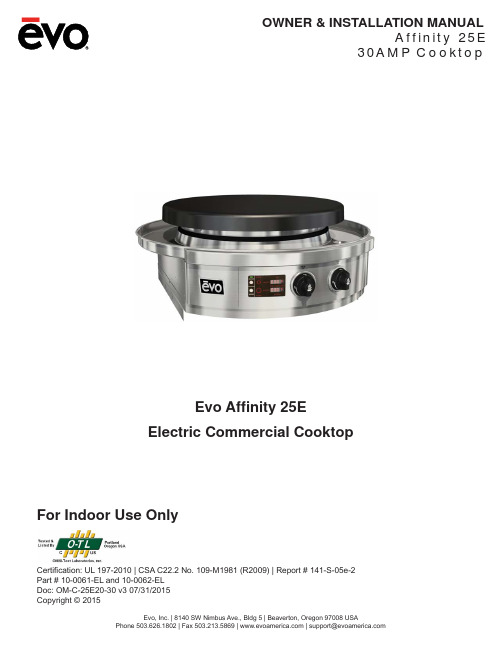
OWNER & INSTALLATION MANUALA f f i n i t y25E30A M P C o o k t o pEvo, Inc. | 8140 SW Nimbus Ave., Bldg 5 | Beaverton, Oregon 97008 USAPhone503.626.1802|Fax503.213.5869||**********************Evo Affi nity 25EElectric Commercial CooktopFor Indoor Use OnlyCertifi cation: UL 197-2010 | CSA C22.2 No. 109-M1981 (R2009) | Report # 141-S-05e-2Part # 10-0061-EL and 10-0062-ELDoc: OM-C-25E20-30 v3 07/31/2015Copyright © 2015INSTALLATION INSTRUCTIONSA f f i n i t y 25EEvo, Inc. | 8140 SW Nimbus Ave., Bldg 5 | Beaverton, Oregon 97008 USAPhone503.626.1802|Fax503.213.5869||**********************2NOTICE THE SERIAL NUMBER AND MODEL INFORMATION LABEL PLATE ISLOCATED UNDERNEATH THE CONTROL PANEL. NOTICE INSTALLATION OF ANY VENT HOODS OR FIRE EXTINGUISHER SYSTEMSMUST CONFORM TO THE NATIONAL, STATE, AND LOCAL BUILDING AND ALL APPLICABLE UNIFORM CONSTRUCTION CODES.NOTICE DURING THE FIRST FEW HOURS OF OPERATION IT IS NORMAL FOR OILSUSED IN THE MANUFACTURING PROCESS AND INSULATING MATERIAL TOBECOME WARM AND GIVE OFF AN ODOR.Evo, Inc. | 8140 SW Nimbus Ave., Bldg 5 | Beaverton, Oregon 97008 USAPhone503.626.1802|Fax503.213.5869||**********************3Evo, I ncorporated w arrants t o t he o riginal c ommercial f oodservice p urchaser t hat t he E vo c ooking, r efrigeration a nd v entilation e quip-ment s hall b e f ree f rom r ust t hrough o n a ll m etal s urfaces a nd s hall b e f ree f rom d efects i n m aterials a nd w orkmanship u nder n ormal a nd reasonable u se f or O ne Y ear f rom t he o riginal d ate o f p urchase f rom E vo, I nc. T his w arranty i s f or t he b ene fit o f t he o riginal u se p urchaser and i s n on-transferable. E vo p romises t o r eplace, a t i ts d etermination, a ny p roduct o r c omponent t hat i s d efective d uring t his i nitial o ne y ear period. O r a s a r esolution, E vo m ay a t i ts o ption r epurchase t he p roduct a t i ts o riginal p urchase p rice. T his i s y our s ole a nd e xclusive r emedy. This warranty is subject to the limitations, exclusions and other provisions listed below.Limitations Involving Materials and Components:Warranty d oes n ot a pply t o n ormal w ear a nd t ear, w hich a re e xpected o ver t he c ourse o f o wnership. T he m aterials a nd c omponents l isted below are covered according to the following schedule from the original date of purchase from Evo:• O ne Y ear –e lectrical a nd e lectronic c omponents [including, b ut n ot l imited t o, e lectronic d isplays, o verlay a nd m embrane s witches,temperature s ensors (RTD a nd K -Value T hermal C ouple), h ot s urface i gniters, c omputers, t ransformers, h eater e lements, relays, igniters, ignition controllers, wiring, switches, encoders, outlets and plugs• One Year – gas components [including, but not limited to, gas regulator, gas hoses, manifold assemblies]• One Year – accessories and repair parts• Ninety (90) Days - refrigeration components [including, but not limited to, compressor, evaporator, pressure control units]The Warranty Registration Card (or online warranty registration form available at /content/commercial-warranty-registration) must be completed and returned/submitted to Evo, Incorporated within 30 days from the date of purchase. The original purchase invoice or payment record must be retained and produced upon request if claims are made under this warranty. To receive a replacement Warranty Registration Card, write or call the address listed at the bottom of this page. Warranties are void if the original serial numbers have been removed, altered, or cannot be readily determined.THIS WARRANTY APPLIES ONLY TO PRODUCTS PURCHASED AND LOCATED WITHIN THE USA OR CANADA.What is NOT COVERED by this warranty:1. Conditions and damages resulting from any of the following:a. Improper or inadequate installation, delivery, use, storage or maintenanceb. Any repair not authorized in writing by Evo, Inc., any modi fi cations, misapplications, or unreasonable use c. Improper setting of any controld. H arsh e nvironmental c onditions, i ncluding, b ut n ot l imited t o, c ontinual s eawater s pray, h igh p ressure w ater, a nd d irect c ontact w ith corrosive chemicals and materialse. Excessive or inadequate electrical, gas, or refrigeration supplyf. Accidents, natural disasters, acts of Godg. Conditions covered by the purchaser’s insurance h. Cleaning supplies and fi lters2. Labor not pre-authorized by Evo, Incorporated, and labor not performed by an authorized Evo service agency or representative3. Pre-authorized warranty labor performed outside of normal business hours, and at overtime and premium rates4. The cost of service or a service call to:a. Identify or correct installation errorsb. Transport the product or component for service to/from the manufacturer or service centerc. Instruct the user of the proper use of the product5. The cost for any inconvenience, personal injury or property damage due to failure of the product, and cost of damage arising out of the transportation of the product which is covered under different terms with the carrier6. Natural variations in color and fi nishes that are inherent to the material and unavoidable (and therefore not defects)ALL I MPLIED W ARRANTIES, I NCLUDING T HE I MPLIED W ARRANTIES O F M ERCHANTABILITY, S UITABILITY, Q UALITY A ND/OR F ITNESS F OR A PARTICULAR P URPOSE, A RE L IMITED I N D URATION T O T HE E XPRESS W ARRANTY P ERIODS S PECIFIED A BOVE F OR T HE P ARTS D ESCRIBED THEREIN. E VO, I NCORPORATED M AKES N O O THER W ARRANTY A ND W ILL N OT B E L IABLE F OR A NY D IRECT O R I NDIRECT, C ONSEQUENTIAL O R INCIDENTAL D AMAGES. S ome s tates d o n ot a llow l imitations o n h ow l ong a n i mplied w arranty l asts, s o t he a bove l imitation m ay n ot a pply to y ou. N either E vo m anufacturer r epresentatives a nd d ealers, n or t he c ommercial e stablishment s elling t his p roduct h as a ny a uthority t o make a ny w arranties o r t o p romise r emedies i n a ddition t o o r i nconsistent w ith t hose s tated a bove. T he m aximum l iability t o E vo, I ncorpo-rated i n a ny e vent, s hall n ot e xceed t he p urchase p rice o f t he p roduct p aid b y t he o riginal c ommercial-purchaser. S ome s tates d o n ot a llow the e xclusion o r l imitation o f i ncidental o r c onsequential d amages, s o t he a bove l imitations o r e xclusions m ay n ot a pply t o y ou. T his w ar-ranty gives you speci fic legal rights, and you may also have other rights which vary from state to state.INSTALLATION INSTRUCTIONSA f f i n i t y 25EEvo, Inc. | 8140 SW Nimbus Ave., Bldg 5 | Beaverton, Oregon 97008 USAPhone503.626.1802|Fax503.213.5869||**********************4INSTALLATION CHECKLISTUNPACK COOKTOP COMPONENTS 5 - 6PREPARE COUNTERTOP FOR INSTALLATION 7 - 11INSERT CHASSIS IN COUNTERTOP 12INSTALL DRIP PAN 13 - 14INSTALL DRIP PAN GASKET 14INSTALL ELECTRICAL CONNECTIONS 15INSTALL COOK SURFACE AND TIGHTEN FASTENERS 16 - 17OPERATOR INSTRUCTIONS 18 - 20ELECTRICAL SCHEMATICS21PAGE #INSTALLATION INSTRUCTIONSA f f i n i t y 25EEvo, Inc. | 8140 SW Nimbus Ave., Bldg 5 | Beaverton, Oregon 97008 USAPhone503.626.1802|Fax503.213.5869||**********************5Cook Surface with Protective Cardboard : Lift and separate cook surface from unit and place next to installation area. Do not remove protective cardboard from cook surface until installation is complete. Use caution when lifting - the cook surface is E EXTREME CAUTION to ensure wiring on bottom of cook surface does not becomeentangled, pulled or damaged during unpacking or installation.Protective Cardboard:drip panprotectivecomplete.Lift UNPACKING COOKTOP COMPONENTS - 1 of 2STEP 1: As you are unpacking the crate, make sure you locate all components beforeinstallation. Keep all protective cardboard on components until installation is complete.INSTALLATION INSTRUCTIONSA f f i n i t y 25EEvo, Inc. | 8140 SW Nimbus Ave., Bldg 5 | Beaverton, Oregon 97008 USAPhone503.626.1802|Fax503.213.5869||**********************6UNPACKING COOKTOP COMPONENTS - 2 of 2STEP 1 CONTINUED: Take care when lifting the cook surface during uncrating. Do not pull or damage wires or connections. Store in a safe place until ready to install.USE EXTREME CAUTION to ensure wiring on bottom of cook surface does not becomeentangled, pulled or damaged during unpacking or installation.INSTALLATION INSTRUCTIONSA f f i n i t y 25EEvo, Inc. | 8140 SW Nimbus Ave., Bldg 5 | Beaverton, Oregon 97008 USAPhone503.626.1802|Fax503.213.5869||**********************736” clearance to ceiling from cooktop surfaceCLEARANCE DIMENSIONSEvo, Inc. | 8140 SW Nimbus Ave., Bldg 5 | Beaverton, Oregon 97008 USAPhone503.626.1802|Fax503.213.5869||**********************8STEP 2: Mark the fi nished position of the Evo Af fi nity 25E drip pan on the countertop using the dimensions shown. The circular dimension of 31-11/16” is the diameter of the drip pan to the outside fl ange material thickness (located to the inside of the half-rolled bead edge). The drip pan cutout must be made precisely to these dimensions (or at a maximum +1/16”) so that the half-rolled top bead on the drip pan edge overhangs the cutout dimension by .25”. (See following page for more details).INSTALLATION INSTRUCTIONSA f f i n i t y25ECOUNTERTOP INSTALLATION (2 of 4)INSTALLATION INSTRUCTIONSA f f i n i t y 25EEvo, Inc. | 8140 SW Nimbus Ave., Bldg 5 | Beaverton, Oregon 97008 USAPhone503.626.1802|Fax503.213.5869||**********************10LQ SIDE VIEWExample of 3/8” tile with substrate for a total of 1-1/2” overall. Make sure you allow for the countertop overhang as shown.fi nished COUNTERTOP INSTALLATION (3 of 4)INSTALLATION INSTRUCTIONSA f f i n i t y25EFRONT VIEWSTEP 3: Construct a bay for the Evo unit with your chosen cabinet system. Position and fasten the supplied mounting brackets 7-21/32” below the fi nished countertop surface.Example: Tiled countertop with substrate.Finished countertop thickness should beCOUNTERTOP INSTALLATION (4 of 4)INSTALLATION INSTRUCTIONS A f f i n i t y 25ESTEP 4:black, red and green208V / 230V, 30AMP 1-Phase, 50-60HzINSERT CHASSIS IN COUNTERTOPINSTALLATION INSTRUCTIONS A f f i n i t y 25ESTEP 5: Slide drip tray over chassis circular skirt positioning spillover slots to thecorresponding slots of the top chassis deck. Notice the drip pan catches showing through the inside cutout locations of the circular chassis skirt. From the inside of the skirt, use each of the three latches to pull the drip pan down into the counter.DRIP PAN INSTALLATIONINSTALLATION INSTRUCTIONSA f f i n i t y25EDRIP PAN AND GASKET INSTALLATIONINSTALLATION INSTRUCTIONS A f f i n i t y 25ESTEP 7: Before picking up cook surface, rotate each of the two front slotted captive fastener screws counter-clockwise and back them out fully. Rest cook surface at rear of chassis on drip pan protective cardboard and connect respective power and temperature sensor leads. For electrical wiring details, refer to the electrical schematic in the back of this guide.CONNECTING COOK SURFACE - ELECTRICAL CONNECTIONSINSTALLATION INSTRUCTIONSA f f i n i t y25EINSTALLING COOK SURFACEINSTALLATION INSTRUCTIONSA f f i n i t y25EINSTALLING COOK SURFACEj-hook and secure with 1/4” x 20 nut.to secure cooking surface to chassis.STEP 9: Open spillover tray doors and tighten nut on end of j-hook located at inside rear ofeach door.Complete electrical installation by connecting 3-wire service line located underneath unit. Use electrical schematic diagram at the back of this guide for reference.OPERATOR INSTRUCTIONS A f f i n i t y 25EINNER 000F .Displays temperature for Inner heater element in Fahrenheit degrees whenever Inner control knob is selected. The Dot mark after F is illuminated whenever the inner heater element is energized. Inner display remains illuminated whenever Inner heater element is selected.OUTER000F .Displays temperature for Outer heater element in Fahrenheit degreeswhenever Outer control knob is selected. The Dot mark after F isilluminated whenever the outer heater element is energized. Outerdisplay remains illuminated whenever Outer element is selected.Depressing the round switch located below the On/Off label switches the unit between powerOn and power Off states. Switching the unit On illuminates a green light above the On/Offlabel indicating the unit is active. Depressing the switch a second time powers down the unit,and cancels previous settings.On/Off Is illuminated whenever there is an increase in temperature adjustment to the Inner or Outer heater control knobs. Set remains illuminated until temperature selected is achieved.SETIs illuminated as a safety feature to indicate cook surface temperature are in excess of 150F° or greater. HOT SURFACEIs illuminated to show actual temperature for both Inner and Outer heater element whenever Mode switch is selected.ACTUALDepressing the Mode button momentarily displays the actual temperature at both Innerand Outer zones of the cook surface. When Mode is fi rst selected, the word Actual isilluminated to indicate the temperatures displayed are the current temperatures for Innerand Outer zones.Mode The Af fi nity 25E Commercial cooktop is provided with a COOK Mode that offers atemperature range between 150F to 525F:Low 150, 165, 175, 200, 225, 250.Med 275, 300, 325, 350, 375, 400.Hi 415, 425, 450, 475, 500, 525.TemperaturesEVO AFFINITY 25E ELECTRIC CONTROL PANEL DISPLAYOPERATOR INSTRUCTIONS A f f i n i t y 25EREMOVABLE SPILLOVER TRAYSThe Af fi nity grill has removable waste pans concealed in doors on both the right and left side of the front control panel. It is very important to monitor the level of spillover in the trays, and immediately empty when they are near full or after each use.Opening Spillover Tray Doors- To open a door, grasp the door at its bottom and pull forward.Do not operate cook top or clean drip pan into spillover slots without waste pans installed inspillover doors. Failure to install waste pan will result in cooking grease contamination to the underside of door. This requires immediate cleaning.Removable waste panAccessDoor Spillover SlotInsert each waste pan all the way to theback of the left and right compartments.Do not allow spillover liquids or debris down spillover slots when doors are open. Any liquids or debris that may fall into this area when doors are open should be immediately wiped with a dry cloth, and keep this area clean at all times.Do not allow the spillover trays to over fl ow, and do not allow full trays to splash over edge when cleaning. Spillover debris and liquids can be hot and cause burns, and/or damage to the internal operation of the grill.OPERATOR INSTRUCTIONSA f f i n i t y25ECOOK SURFACE MAINTENANCERegular cleaning and care for your Evo Affi nity 25E cooktop will keep it looking and functioning it’s best.The cook surface is designed to hold a fi ne layer of cooking oil creating a ‘seasoning’ on its surface. Thisseasoning promotes a non-stick cooking surface and is easily maintained.Caring for Evo’s cook surface is much like maintaining cast iron cookware. When the surface requires cleaning,there are a few basic cleaning techniques to use. For quick and routine cleaning between preparations, a metalspatula or scraper works for removing the majority of surface debris. For tougher areas or where sugars glazethe cook surface, pour a small amount of warm water on the soiled surface while the grill is warm and scrape thedebris away with a spatula. Heat the cook surface to a high temperature and allow the sticky debris to becomebrittle. Once the debris is brittle, use the spatula or scraper to remove it. Afterwards wipe the cook surface with vegetable oil again before cooking.To condition the Evo cook surface you should use the grill cleaning kit supplied with your grill. The grill cleaning kit contains a blue grill pad handle, grill cleaning screens, and grill grey polishing pads. Use the polishing pad afterthe grill cleaning pads to achieve a smooth cooking surface for the most delicate foods and applications.To use a grill cleaning screen: With a warm cook surface, place one gray polishing pad between the grill handlebase and the grill screen, so the grill screen makes direct contact with the cooking surface. Pour a small amountof vegetable oil on the cook surface and scrub the surface in a circular motion. The gray polishing pad allowsexcess oil to be absorbed and scours the cooking surface of carbonized debris. When fi nished scrubbing, wipethe surface down with a paper towel or cotton terry cloth.The drip pan located just below the cook surface is designed to catch food debris and drippings from the cooksurface. We recommend cleaning the drip pan after your grill has cooled to prevent the possibility of touchinghot adjoining surfaces. The drip pan is easy to wipe out with soap and water using a kitchen sponge. For added convenience, two removable stainless ninth-pans are mounted inside doors at right and left side of the front control panel for collecting drip pan debris and spill overs. These spillover trays can be easily washed by hand or in a dishwasher. Be sure to empty the spillover trays after every use, and at a minimum, whenever they appear halffull.All the stainless steel components on your grill can be easily polished using a stainless steel cleaner/polish. Information about purchasing replacement grill cleaning and polishing pads is available on our Website. The Evoweb site address is: .Cooking TechniquesStovetop Cooking and Heat ZonesYou can use Evo’s cook surface similar to the burners on your kitchen stove top. Adjust Evo’s heater elements to control the temperatures of the cook surface “heat zones.” Evo’s circular grill top is divided into two distinct zones.The center control panel knob controls the “inner heat zone,” which is also the inner circle of the cook surface at approximately an 11” radius from the center of the cook surface. The outer control panel knob controls the “outerheat zone,” which is the outer circle of the cook surface. Because the cook surface is made of heavy steel, it takes approximately 10 minutes from a cold start to completely heat the surface. With a pre-heated cook surface, if youadjust one of the heater elements, you will have to wait momentarily before the heat zone adjusts to temperature.Thank You For Cooking With Evo!INSTALLATION INSTRUCTIONSA f f i n i t y 25EEvo, Inc. | 8140 SW Nimbus Ave., Bldg 5 | Beaverton, Oregon 97008 USAPhone503.626.1802|Fax503.213.5869||**********************2130AMP ELECTRICAL SCHEMATICPART #: 10-0062-EL & 10-0061-EL 208V - 230V, 1-Phase, 50-60Hz 30AMP Dedicated Circuit 208V / 5.37 kVA。
golo系列产品使用说明书

g o l o系列产品使用说明书030101(总40页)--本页仅作为文档封面,使用时请直接删除即可----内页可以根据需求调整合适字体及大小--golo 系列产品使用说明书更新日期:2014-05-273版权所有!未征得深圳市轱辘软件开发有限公司(下称“轱辘公司”)的书面同意,任何公司或个人不得以任何形式(电子、机械、影印、录制或其它形式)对本说明书进行复制和备份。
本手册专为轱辘产品的使用而设计,对于将之用于指导其它设备操作而导致的各种后果,本公司不承担任何责任。
本手册及其包含的所有范例若有更改,恕不另行通知。
因使用者个人或第三方的意外事故,滥用、误用该设备,擅自更改、修理该设备,或未按轱辘公司的操作与保养要求而致使设备损坏、遗失所产生的费用及开支等,轱辘公司及其分支机构不承担任何责任。
对于使用其它选用配件或损耗品而非轱辘公司原装产品或轱辘公司认可之产品而导致该设备损坏或出现问题,轱辘公司不承担任何责任。
正式声明:本说明书所提及之其它产品名称,目的在于说明本设备如何使用,其注册商标所有权仍属原公司。
本设备供专业技术人员或维修人员使用。
注册商标i轱辘公司已在中国及海外若干国家进行了商标注册,其标志为LAUNCH。
在轱辘公司之商标、服务标志、域名、图标和公司名称还未注册之国家,轱辘公司声明其对未注册商标、服务标志、域名、图标和公司名称仍享有其所有权。
本手册所提及之其它产品及公司名称的商标仍属于原注册公司所有。
在未得到拥有人的书面同意之前,任何人不得使用轱辘公司或所提及的其它公司之商标,服务标志,域名,图标,公司名称。
您可以访问轱辘网址:了解轱辘产品信息;或写信至:中国深圳市龙岗区坂雪岗工业区五和大道北元征工业园深圳市轱辘软件开发有限公司客户服务中心收,与轱辘公司进行联系,征得其手册使用权之书面同意。
ii使用前须知✧此说明书适用于golo系列产品的Android与iOS版本;✧说明书内所有插图仅用作参考,具体请以软件实际显示为准;✧本仪器为精密电子仪器,使用中切勿摔碰。
One 操作说明说明书
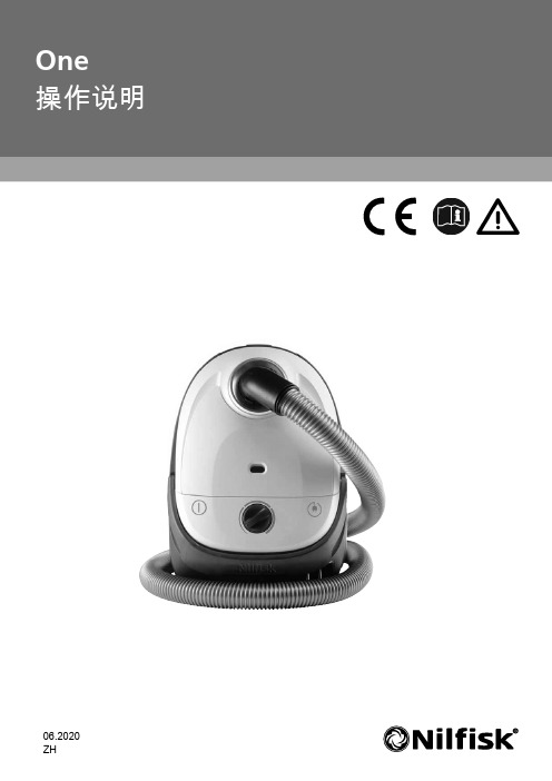
06.2020 ZH首次使用机器之前,请务必仔细通读本指导手册。
保管好这些说明以备将来使用。
本机器不用于抽吸有害材料或气体,这样做可能会给相关人员带来严重的健康风险。
不得将本机器用于抽吸水或其他液体。
切勿拾取针或玻璃碎片等尖锐物体。
切勿拾取燃烧或冒烟的任何物体,例如香烟、火柴或热灰。
本机器适合在 0 °C 到 60 °C 的室内干燥环境下使用和存放。
切勿在室外使用本机器。
在激活自动电缆回卷的情况下,电缆末端的插头可能会在回卷的最后阶段摆动,因此务必多加小心。
建议您在回卷时握住插头。
切勿用湿手操作本机器。
在拔下插头之前,请关闭机器。
要拔下插头,请握住插头,而不是拉拔电线。
切勿通过电线来拖拽机器。
如果电线有任何损坏迹象,则不得使用本机器。
定期检查电线是否损坏,特别要检查电线是否被挤压、门掩或辗压。
若机器出现故障,则切勿使用。
如果机器发生坠落、损坏、留置室外或与水接触,请让授权服务中心对机器进行检查。
不应对机械或电气安全装置进行更改或修改。
必须由授权服务中心开展任何维修工作。
只能使用当地经销商提供的原装集尘袋、原装过滤器和原装附件。
使用未经授权的集尘袋和过滤器将令担保失效。
在开始更换集尘袋或过滤器之前,请关闭机器并拔下插头。
握住插头,而不是拉拔电线。
如果电源线损坏,则必须由制造商、其服务代理或具有同类资格的人员进行更换,以免发生危险。
在使用涡轮喷嘴时,切勿用手触摸旋转部件。
对于 8 岁及以上儿童以及身体机能、感知能力或智力低下人士或缺乏经验者,如果有人监督或指导其如何安全地使用本电器并已了解相关危险,则可以使用本电器。
切勿让儿童在无人监管下清洁电器或执行用户维护。
必须对儿童加以监督以确保他们不会拿电器玩耍。
切勿给非充电电池充电。
充电前,从电器中取出充电电池。
切勿混用不同类型的电池或混用新旧电池。
装入电池时,注意确保极性正确。
从电器中取出电量耗尽的电池,并安全地进行处理。
GE LOGIQ E10 Series 产品说明书

Enabling Interventional Procedures LOGIQ E10 SeriesEMPOWERING YOU TO MAKE THE DIFFERENCENext-level confidence in needle planning & guidanceConfident diagnosisThe extraordinary image quality of the LOGIQ E10 Series gives clinicians the assurance of detailed visualization when performing biopsies, ablations or treating patients.Auto-optimized images: The cSound Imageformer automatically and continuously delivers images of high quality across a wide range of clinical scenarios.Radiant flow™: Provides a near-3D look to support detailed vascular imaging, especially when combined with Micro Vascular Imaging (MVI).MVI: High-definition flow mode helps clinicians visualize small vessels in masses and organ perfusion. Further enhanced when used with RadiantChoice of high-performance probes:probes deliver high fidelity and wide bandwidth for deep penetration and high resolution. Available with Verza Guidance, which has five angles for needle visualization for precise placement.Comprehensive toolsThe LOGIQ E10 Series provides robust tools to increase the speed and precision of diagnosis, guidance and treatment.Volume Navigation: The LOGIQ E10 Series offers advanced capabilities for image-guided procedures, including:• Fusion Imaging: Merge real-time ultrasound with a volume DICOM® dataset (CT, MR, PET/CT, CBCT, SPECT and 3D CEUS) to help increase precision in image-guided interventional procedures• Needle Tip Tracking: Helps users navigate interventional procedures in plane or out of plane. Available Virtual Tracking tool displays a projected view of the needle during procedures • 2D/3D GPS Tracking: Visually track position during a scan using GPS-like technology, and mark selected points of interest B-Steer+:speed and confidence in needle guidance procedures.Contrast Enhanced Ultrasound (CEUS):for pre- and post-ablation assessment of lesion vascularity orresidual tumor.Photo Assistant app:an Androidto the ultrasound system for inclusion with the clinical images –providing valuable context for the reviewing physician.Operatea LOGIQ E10 system from anDual Image CF Pancreas, C1-6-D Pediatric Kidney B-Flow, L2-9-DConcise workflowThe LOGIQ E10 Series can help you achieve new levelsof workflow efficiency, so you have more time tofocus on patients.Auto-registration for Fusion Imaging: Sophisticated navigational toolshelp increase precision and accuracy of image-guided interventional procedures.The Active Tracker enables one-click auto-registration of CT, MR, CBCT, and3D CEUS images that enhances accuracy and ease in managing patient motion,breathing and transmitter movements.Exam Comparisons: View previous exams side-by-side with real-time images.Easy Access to PACS pushes previous studies to device without interruptingworkflow. Multi-Modality Query Retrieve enables import of DICOM data frommultiple modalities.Smart Assistant: Automatically launches the preferred setting and probewhen the user selects an exam type, reducing keystrokes and helpingto ensure quality imaging.Exceptional mobility: Systems easily fit into crowded suites.Power Assistant battery eliminates the need for re-boot, andyou can even scan on battery power. On-board storageensures supplies are at hand.Liver Contrast Enhanced Ultrasound (CEUS) with CT using VolumeNavigation, C1-6-DLiver mass image using CEUS with L3-9i-DSmart investmentGE Healthcare accelerates innovation with the LOGIQ E10 Series – making it the smart choice for now and in the future. The systems are available with a full suite of robust features and scalable options.A to A digital platform: Stay at the forefront of clinical imaging with our A to A digital platform, specifically engineered so you can add next-generation capabilities in the years ahead.Familiar user interface: The new LOGIQ E10 Series offers greater functionality whilemaintaining the ease of operation and satisfying user experience that has become ahallmark of LOGIQ interface design.SonoDefense: GE Healthcare’s multi-layer approach to cybersecurity helps keep thesystems safe and functional in the face of cyberthreats and helps protect patient datafrom unauthorized access.Digital support: Wide choice of efficiency tools to help users, administrators, and operationsstaff improve productivity, including remote preset management, performance analytics,software/security updates, live clinical training, and advanced system diagnostics.Product may not be available in all countries and regions. Full product technical specifications are available uponrequest. Contact a GE Healthcare Representative for more information. Please visit /promotional-locations.Data subject to change.© 2020 General Electric Company – All rights reserved.GE, the GE Monogram, LOGIQ, XDclear, cSound, and Radiant flow are trademarks of General Electric Company.Android is a trademark of Google LLC. DICOM is a trademark of National Electrical Manufacturers Association.Verza is a trademark of CIVCO Medical Solutions.Reproduction in any form is forbidden without prior written permission from GE. Nothing in this material shouldbe used to diagnose or treat any disease or condition. Readers must consult a healthcare professional.To determine whether individual features are standard or optional, consult with your GE Healthcare salesrepresentative.October 2020 JB00141XX。
ego1开发板使用手册
ego1开发板使用手册一、ego1开发板简介ego1开发板是一款超酷的开发板呢。
它有着丰富的功能和接口,能让我们在学习和开发的过程中大展身手哦。
它可以用于多种数字电路和逻辑设计的实验与项目开发,真的是超级实用。
二、硬件组成1. 电源接口•这个电源接口可是很重要的哦。
它为整个开发板提供电力支持。
一般我们要按照规定的电压范围来接入电源,不然可能会损坏开发板的,要特别小心呀。
2. 逻辑器件•这里面有各种逻辑门电路等逻辑器件呢。
它们就像一个个小助手,帮助我们实现各种逻辑功能。
在使用的时候,我们要熟悉它们的功能特性,这样才能更好地进行电路设计哦。
3. 输入输出接口•这些接口是开发板与外界交互的通道呀。
我们可以通过它们连接外部设备,像按键、LED灯等。
在连接的时候,一定要注意接口的类型和对应的功能,可不能接错了,不然就达不到我们想要的效果啦。
三、软件环境搭建1. 安装开发工具•我们需要安装专门用于ego1开发板的开发工具哦。
这个过程可能会有点复杂,但是只要按照步骤来,就没有问题的啦。
在安装的时候,要注意选择正确的版本,不同的版本可能会有一些功能上的差异呢。
2. 配置开发环境•安装好开发工具后,就需要进行环境配置了。
要设置一些参数,比如编译器的路径之类的。
这一步可不能马虎哦,因为如果环境配置不正确,可能会导致程序无法编译或者运行出错的。
四、简单示例程序运行1. 选择示例程序•开发工具一般会自带一些示例程序的。
我们可以先从这些示例程序入手来熟悉开发板的使用。
这些示例程序涵盖了开发板的各种基本功能,非常适合初学者哦。
2. 编译示例程序•选中示例程序后,就可以进行编译了。
编译的时候要耐心等待,要是编译过程中出现错误提示,不要慌,仔细查看错误信息,一般都是一些语法错误或者变量未定义之类的小问题,很好解决的呢。
3. 下载运行•编译成功后,就可以将程序下载到开发板上运行了。
看着自己的程序在开发板上运行起来,那种感觉超棒的哦。
- 1、下载文档前请自行甄别文档内容的完整性,平台不提供额外的编辑、内容补充、找答案等附加服务。
- 2、"仅部分预览"的文档,不可在线预览部分如存在完整性等问题,可反馈申请退款(可完整预览的文档不适用该条件!)。
- 3、如文档侵犯您的权益,请联系客服反馈,我们会尽快为您处理(人工客服工作时间:9:00-18:30)。
Ego one功能说明书(带温控)
快速使用:
普通发热丝最低0.2R-2R全功率输出。
NI200发热丝0.1R-2R。
恒温330摄氏度。
不烧棉。
开关机:1.5S内快速按键5次实行开机,此时按键灯闪烁3次;同样地,1.5S内快速按键5次实行关机。
吸烟:
普通发热丝——持续按按钮实行吸烟,此时按键灯会常亮;
NI200——恒温250摄氏度
充电:插上USB数据线,然后接上电源(如插到电脑或插座上)。
USB旁红灯亮起,充满后熄灭。
正常充电电流500mA 左右。
主板不检测充电状态。
电阻检测:
1.空载检测,吸烟灯亮闪三次,不输出。
2.当输出端负载<0.05Ω,按键工作时,按键灯快闪3次,提示输出负载过低或短路。
短路保护功能:
1.
2.工作前短路,按键工作时闪烁3次并关断输出。
雾化器保护功能:长按按键15秒,关断输出,闪烁白灯5下。
电池低电量提醒:低于3.5V 吸烟灯一直闪,有输出。
可以正常工作。
低电压保护:
吸烟前,电池电压低于3.2V,检测一次,闪按键灯5下,无输出。