IXGH12N60C中文资料
c612芯片组

c612芯片组
C612芯片组是英特尔的服务器级芯片组,专为企业级工作站和服务器设计。
芯片组是计算机内部的重要组成部分,负责连接和协调处理器、内存、硬盘和其他外设之间的数据传输和通信。
C612芯片组采用了英特尔的QuickPath Interconnect技术,具有高带宽和低延迟的特点,能够支持多处理器系统和高性能计算。
它支持英特尔Xeon E5和E7系列处理器,这些处理器采用了14纳米制程工艺,拥有多核和超线程技术,能够充分发挥多线程计算和并行处理的优势。
C612芯片组具有丰富的扩展性和可靠性特性。
它支持大容量的内存,最高可支持24个内存插槽,能够容纳192GB至
1.5TB的内存容量,充分满足大规模数据处理和虚拟化环境的需求。
同时,C612芯片组还支持英特尔的快速存储技术,如SATA 6Gb/s和USB 3.0等,提供了高速的数据传输和存储功能。
C612芯片组还具有可靠性和可管理性的特点。
它支持英特尔的虚拟化技术,如VT-x和VT-d,能够提供安全可靠的虚拟化环境。
此外,C612芯片组还支持英特尔的管理引擎技术,具有远程管理和监控功能,可以方便地进行系统管理和维护。
总结来说,C612芯片组是专为企业级工作站和服务器设计的高性能芯片组。
它具有高带宽、低延迟、丰富的扩展性和可管
理性特点,能够满足大规模数据处理和虚拟化环境的需求,是企业级计算机系统的重要组成部分。
XNX系列氢氧化物传感器的产品介绍说明书
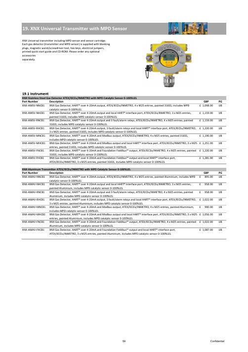
XNX Gas Detector, HART® over 4-20mA output, ATEX/IECEx/INMETRO, 4 x M25 entries, painted 316SS, includes MPD XNX Gas Detector, HART® over 4-20mA output and local HART® interface port, ATEX/IECEx/INMETRO, 3 x M25 entries, XNX Gas Detector, HART® over 4-20mA output and 3 fault/alarm relays, ATEX/IECEx/INMETRO, 4 x M25 entries, painted6970Confidential71Confidential72Confidential73ConfidentialPart NumberDescriptionPGXNX-AMAE-FNNNN XNX Transmitter, HART® over 4-20mA and Foundation Fieldbus™ output, ATEX/IECEx/INMETRO, 4 x M25 entries, painted Aluminium, configured for XNX toxic and oxygen sensors895.00£ UB XNX-AMAE-FHNNNXNX Transmitter, HART® over 4-20mA and Foundation Fieldbus™ output and local HART® interface port, ATEX/IECEx/INMETRO, 3 x M25 entries, painted Aluminium, configured for XNX toxic and oxygen sensors958.00£ UBXNX Stainless Steel Transmitter UL/CSA for use with XNX Toxic and Oxygen Sensors Part Number Description GBP PGXNX-UTSE-NNNNN XNX Transmitter, HART® over 4-20mA output, UL/CSA, 4 x 3/4"NPT entries, painted 316SS, configured forXNX toxic and oxygen sensors975.00£ UB XNX-UTSE-NHNNN XNX Transmitter, HART® over 4-20mA output and local HART® interface port, UL/CSA, 3 x 3/4"NPTentries, painted 316SS, configured for XNX toxic and oxygen sensors1,037.00£ UB XNX-UTSE-RNNNN XNX Transmitter, HART® over 4-20mA output and 3 fault/alarm relays, UL/CSA, 4 x 3/4"NPT entries,painted 316SS, configured for XNX toxic and oxygen sensors1,037.00£ UB XNX-UTSE-RHNNN XNX Transmitter, HART® over 4-20mA output and 3 fault/alarm relays and local HART® interface port,UL/CSA, 3 x 3/4"NPT entries, painted 316SS, configured for XNX toxic and oxygen sensors 1,098.00£ UB XNX-UTSE-MNNNN XNX Transmitter, HART® over 4-20mA and Modbus output, UL/CSA, 4 x 3/4"NPT entries, painted 316SS, configured for XNX toxic and oxygen sensors1,068.00£ UB XNX-UTSE-MHNNN XNX Transmitter, HART® over 4-20mA and Modbus output and local HART® interface port, UL/CSA, 3 x 3/4"NPT entries, painted 316SS, configured for XNX toxic and oxygen sensors1,128.00£ UB XNX-UTSE-FNNNN XNX Transmitter, HART® over 4-20mA and Foundation Fieldbus™ output, UL/CSA, 4 x 3/4"NPT entries, painted 316SS, configured for XNX toxic and oxygen sensors1,098.00£ UB XNX-UTSE-FHNNNXNX Transmitter, HART® over 4-20mA and Foundation Fieldbus™ output and local HART® interface port, UL/CSA, 3 x 3/4"NPT entries, painted 316SS, configured for XNX toxic and oxygen sensors1,159.00£ UBXNX Aluminium Transmitter UL/CSA for use with XNX Toxic and Oxygen Sensors Part Number Description GBP PGXNX-UTAE-NNNNN XNX Transmitter, HART® over 4-20mA output, UL/CSA, 4 x 3/4"NPT entries, painted Aluminium,configured for XNX toxic and oxygen sensors767.00£ UB XNX-UTAE-NHNNN XNX Transmitter, HART® over 4-20mA output and local HART® interface port, UL/CSA, 3 x 3/4"NPTentries, painted Aluminium, configured for XNX toxic and oxygen sensors831.00£ UB XNX-UTAE-RNNNN XNX Transmitter, HART® over 4-20mA output and 3 fault/alarm relays, UL/CSA, 4 x 3/4"NPT entries,painted Aluminium, configured for XNX toxic and oxygen sensors831.00£ UB XNX-UTAE-RHNNN XNX Transmitter, HART® over 4-20mA output and 3 fault/alarm relays and local HART® interface port,UL/CSA, 3 x 3/4"NPT entries, painted Aluminium, configured for XNX toxic and oxygen sensors 895.00£ UB XNX-UTAE-MNNNN XNX Transmitter, HART® over 4-20mA and Modbus output, UL/CSA, 4 x 3/4"NPT entries, painted Aluminium, configured for XNX toxic and oxygen sensors863.00£ UB XNX-UTAE-MHNNN XNX Transmitter, HART® over 4-20mA and Modbus output and local HART® interface port, UL/CSA, 3 x 3/4"NPT entries, painted Aluminium, configured for XNX toxic and oxygen sensors927.00£ UB XNX-UTAE-FNNNN XNX Transmitter, HART® over 4-20mA and Foundation Fieldbus™ output, UL/CSA, 4 x 3/4"NPT entries, painted Aluminium, configured for XNX toxic and oxygen sensors895.00£ UB XNX-UTAE-FHNNNXNX Transmitter, HART® over 4-20mA and Foundation Fieldbus™ output and local HART® interface port, UL/CSA, 3 x 3/4"NPT entries, painted Aluminium, configured for XNX toxic and oxygen sensors958.00£ UB74Confidential75Confidential76Confidential77ConfidentialXNX Aluminuim Transmitter ATEX/IEC for use with Optima Plus and Searchline Excel Detectors78ConfidentialXNX Aluminuim Transmitter UL/CSA for use with Optima Plus and Searchline Excel DetectorsExcel kits including standard XNX transmitter configured with HART® over 4-20mA output and local IS HART® port. For Excel kits includingother XNX transmitter configurations contact Honeywell Analytics. A calibration has to be ordered with every XNX Excel kit.Excel gas calibration curve to be selected from section 29.2 and to be ordered additionally.23.1 InstrumentExcel kits including standard XNX transmitter with HART® over 4-20mA outputs and local IS HART® port.Excel Short Range 5m – 40m (15ft - 130ft)Part Number Description GBP PG 02104-N-XSAA XNX Excel line-of-sight gas detection system, short range (5 to 40m), 4 to 20mA and HART® outputs, ATEX/IECEx, fully wired with flexible conduit, electro polished 316SS. Includes Tx, Rx, aluminimum XNX, Ex e junction box with M20/M25 cable entries, 316SS mounting plates, brackets and hardware 6,518.00£ UA02104-N-XSSAXNX Excel line-of-sight gas detection system, short range (5 to 40m), 4 to 20mA and HART® outputs, ATEX/IECEx, fully wired with flexible conduit, electro polished 316SS. Includes Tx, Rx, stainless steel XNX, Ex e junction box with M20/M25 cable entries, 316SS mounting plates, brackets and hardware6,649.00£ UA 02104-N-XSAUXNX Excel line-of-sight gas detection system, short range (5 to 40m), 4 to 20mA and HART® outputs, UL, fully wired with flexible conduit, electro polished 316SS. Includes Tx, Rx, aluminimum XNX, junction box with 3/4"NPT cable entries, 316SS mounting plates, brackets and hardware6,827.00£ UA 02104-N-XSSUXNX Excel line-of-sight gas detection system, short range (5 to 40m), 4 to 20mA and HART® outputs, UL, fully wired with flexible conduit, electro polished 316SS. Includes Tx, Rx, stainless steel XNX, junction box with 3/4"NPT cable entries, 316SS mounting plates, brackets and hardware6,960.00£ UA 02104-N-XSACXNX Excel line-of-sight gas detection system, short range (5 to 40m), 4 to 20mA and HART® outputs, FM/CSA, fully wired with flexible conduit, electro polished 316SS. Includes Tx, Rx, aluminimum XNX, junction box with 3/4"NPT cable entries, 316SS mounting plates, brackets and hardware6,539.00£ UA 02104-N-XSSCXNX Excel line-of-sight gas detection system, short range (5 to 40m), 4 to 20mA and HART® outputs, FM/CSA, fully wired with flexible conduit, electro polished 316SS. Includes Tx, Rx, stainless steel XNX, junction box with 3/4"NPT cable entries, 316SS mounting plates, brackets and hardware6,671.00£ UA 02104-N-NSNAExcel line-of-sight gas detection system (without XNX, please order required XNX separately), short range (5 to 40m), 4 to 20mA output, ATEX/IECEx, fully wired with flexible conduit, electro polished 316SS. Includes Tx, Rx, 316SS mounting plates, brackets and hardware. XNX and junciton boxes to be ordered seperately.5,591.00£ UA83Confidential。
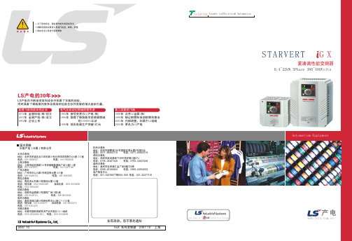
LG iGX样本(中文版)
-Solution Leader in Electrics& Automation
STARVERT G X
紧凑高性能变频器
0.4~22kW 3Phase 380~480Volts
Automatiom Equipment
New Name of
小心选择电流断路器. 当变频器上电的时候,可能有大 的浪涌电流涌入
为了使变频器长时间运行在高性能状态下,请把变频器安 装在正确的方向的适当的位置,留出适当的空间.不正确的 端子接线会导致设备的损坏.
有必要的情况下再安装。 如果安装了,不要用它来 启动和停止变频器。否则, 容易缩短产品的使用寿命。
控制连线
安全警告
为了您的安全,请在操作前先阅读说明书 请联系授权的服务人员进行检查、维修、调整 请由专业人员进行拆除维修
LS产电的30年
LS产电在不断地变革和成长中积累了丰富的经验。 同时具备了面临激烈竞争及挑战时也能生存并发展的强大组织力量。
取得飞跃和成长的企业 1974年 金星机电(株)创立 1987年 金星产电(株)设立 1994年 企业上市
电气及自动化领域的领先者 1995年 商号变更为LG产电(株) 1996年 取得了韩国最早变频器领域
的ISO9001认证 1998年 低压电器生产突破1亿台
第二次质的飞跃 1999年 合并LG金属(株) 1999年 转让铜管和自动销售机事业 2003年 内部调整,归属于LG电缆 2005年 更名为LS产电
动能缓冲
电源突降或瞬时掉电的情况下,变频器会出现欠压故障并保护停机。使 用此功能后,变频器在电源出现问题时会根据减速方式或直流电压参考方式 控制输出频率,利用电机产生的回馈能量维持直流侧电压以延长出现欠压保 护的时间,实现电源突降或瞬时掉电的情况下变频器能持续工作。
JHW12N60C-U mos管、场效应管

Ciss Coss
VDS=25V, VGS =0V, f=1.0MHZ
- 1480 1900 pF - 200 27e transfer capacitance
Crss
- 25 35 PF
3/6
电特性 ELECTRICAL CHARACTERISTICS
开关特性 Switching Characteristics
Rdson(@Vgs=10V) 0.8 Ω
Qg
42nC
用途
z 高频开关电源 z 电子镇流器 z UPS 电源
APPLICATIONS z High efficiency switch
mode power supplies z Electronic lamp ballasts
based on half bridge z UPS
55~+150
引线最高焊接温度
Maximum Lead Temperature for
TL
300
Soldering Purposes
*漏极电流由最高结温限制
*Drain current limited by maximum junction temperature
单位 Unit V A A A V mJ A mJ V/ns W
TJ=25℃ 4:脉冲测试:脉冲宽度≤300μs,占空比≤2% 5:基本与工作温度无关
Notes: 1:Pulse width limited by maximum junction
temperature 2:L=11.2mH, IAS=12A, VDD=50V, RG=25 Ω,Starting
TJ=25℃ 3:ISD ≤12A,di/dt ≤300A/μs,VDD≤BVDSS, Starting
H3N技术应用手册第4版

2.1 外形尺寸及安装尺寸 ......................................................................................... 4 2.2 安装环境 ........................................................................................................... 5 2.3 驱动器连接端子................................................................................................. 6 2.4 安装和配线时的注意事项 .................................................................................. 7
3.2.1 CN1 外形 ................................................................................................... 8 3.2.2 CN1 定义 ................................................................................................... 9 3.3 CN2 接口 .......................................................................................................... 9 3.3.1 CN2 外形 ................................................................................................... 9 3.3.2 CN2 定义 ................................................................................................. 10 3.4 输入输出接口类型 ........................................................................................... 11 3.4.1 数字信号输入接口.................................................................................... 11 3.4.2 数字信号输出接口.................................................................................... 11 3.4.3 脉冲指令输入接口.................................................................................... 12 3.4.4 模拟量输入接口 ....................................................................................... 13 3.4.5 编码器信号输出接口 ................................................................................ 13 3.4.6 编码器 Z 信号集电极开路输出接口.......................................................... 15 3.4.7 光电编码器信号输入接口......................................................................... 15 3.5 标准接线方式 .................................................................................................. 15 3.5.1 位置控制下标准接线图 ............................................................................ 15 3.5.2 速度/转矩模拟量控制下标准接线图 ......................................................... 17
IXGP7N60C;IXGA7N60C;中文规格书,Datasheet资料

© 2002 IXYS All rights reserved98564A (06/02)Symbol Test Conditions Maximum RatingsVCES TJ= 25°C to 150°C600VVCGR TJ= 25°C to 150°C; RGE= 1 MΩ600VVGESContinuous±20VVGEMTransient±30VI C25TC= 25°C 14AI C90TC= 90°C 7AI CM TC= 25°C, 1 ms 30ASSOA VGE = 15 V, TVJ= 125°C, RG= 22 Ω ICM= 14A(RBSOA)Clamped inductive load, L = 300 µH @ 0.8 VCESPC TC= 25°C 54WTJ-55 (150)TJM150CTstg-55 (150)Maximum lead temperature for soldering 300C 1.6 mm (0.062 in.) from case for 10 sMd Mounting torque, (TO-220) M3 0.45/4 Nm/lb.in.M3.5 0.55/5 Nm/lb.in.Weight TO-220 4g TO-263 2 g Symbol Test Conditions Characteristic Values(TJ = 25°C, unless otherwise specified)min.typ.max.BVCESIC= 250 µA, VGE= 0 V600VVGE(th)IC= 250 µA, VCE= VGE2.5 5.5VI CES VCE= 0.8 • VCESTJ= 25°C100µA VGE= 0 V TJ= 125°C500µAI GES VCE= 0 V, VGE= ±20 V±100nAVCE(sat)IC= IC90, VGE= 15 V 2.0 2.7VFeatures•International standard packagesJEDEC TO-263 surfacemountable and JEDEC TO-220 AB•High frequency IGBT•High current handling capability•HiPerFAST TM HDMOS TM process•MOS Gate turn-on-drive simplicityApplications•Uninterruptible power supplies (UPS)•Switched-mode and resonant-modepower supplies•AC motor speed control•DC servo and robot drives•DC choppersAdvantages•High power density•Suitable for surface mounting•Very low switching losses for highfrequency applicationsVCES=600VIC25=14AVCE(sat)= 2.7Vtfi=45nsG = Gate, C = Collector,E = Emitter,TAB = CollectorHiPerFAST TM IGBT Lightspeed TM Series IXGA 7N60CIXGP 7N60CGEC (TAB)TO-263 AA (IXGA)TO-220AB (IXGP)IXYS reserves the right to change limits, test conditions, and dimensions.IXYS MOSFETs and IGBTs are covered by one or more of the following U.S. patents:4,835,5924,881,1065,017,5085,049,9615,187,1175,486,7156,306,728B14,850,0724,931,8445,034,7965,063,3075,237,4815,381,025SymbolTest ConditionsCharacteristic ValuesTO-220 AB Outlinelimeter Inches Min.Max.Min.Max.A 12.7013.970.5000.550B 14.7316.000.5800.630C9.9110.660.3900.420D 3.54 4.080.1390.161E 5.85 6.850.2300.270F 2.54 3.180.1000.125G 1.15 1.650.0450.065H 2.79 5.840.1100.230J 0.64 1.010.0250.040K 2.54BSC 0.100BSC M 4.32 4.820.1700.190N 1.14 1.390.0450.055Q 0.350.560.0140.022R2.29 2.790.0900.110TO-263 AA OutlinePins:1 - Gate2 - Collector3 - Emitter4 - CollectorBottom SideMin. Recommended Footprint (Dimensions in inches and mm)分销商库存信息:IXYSIXGP7N60C IXGA7N60C。
IXGR12N60C;中文规格书,Datasheet资料
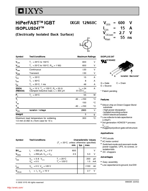
© 2002 IXYS All rights reservedSymbol Test Conditions Maximum RatingsV CES T J = 25°C to 150°C600V V CGR T J = 25°C to 150°C; R GE = 1 M Ω600V V GES Continuous ±20V V GEM Transient ±30V I C25T C = 25°C 15A I C90T C = 90°C 8A I CMT C = 25°C, 1 ms48A SSOAV GE = 15 V, T VJ = 125°C, R G = 33 Ω I CM = 24A(RBSOA)Clamped inductive load, L = 300 µH @ 0.8 V CESP C T C = 25°C55W T J -40 ... +150°C T JM 150°CT stg -40 ... +150°C V ISOL Isolation Voltage 2500V Weight5g Maximum lead temperature for soldering 300°C1.6 mm (0.062 in.) from case for 10 s98663B (02/02)Symbol Test ConditionsCharacteristic Values(T J = 25°C, unless otherwise specified)min.typ.max.BV CES I C = 250 µA, V GE = 0 V 600V V GE(th)I C= 250 µA, V GE = V GE2.55.0V I CES V CE = 0.8 V CES T J = 25°C 200µA V GE = 0 VT J = 125°C1.5mA I GES V CE = 0 V, V GE =±20 V ±100nA V CE(sat)I C= I T , V GE = 15 V2.7VV CES =600 VI C25=15A V CE(sat)= 2.7 Vt fi(typ)=55ns HiPerFAST TM IGBTISOPLUS247TM(Electrically Isolated Back Surface)G = Gate C = DrainE = Source* Patent pendingFeatureslSilicon chip on Direct-Copper-Bond substrate- High power dissipation - Isolated mounting surface - 2500V electrical isolationlLow collector to tab capacitance (<35pF)l 3rd generation HDMOS TM process V CE (sat)lRugged polysilicon gate cell structureApplicationslPFC circuitsl AC motor controllSwitched-mode and resonant-mode power supplies, UPS, no screws, or isolation foils lDC choppersAdvantagesl Easy assemblylLow capacitance to ground, low EMIIXGR 12N60CISOPLUS 247E153432Isolated Backside*IXYS reserves the right to change limits, test conditions, and dimensions.IXYS MOSFETS and IGBTs are covered by one or more of the following U.S. patents:4,835,5924,881,1065,017,5085,049,9615,187,1175,486,7156,306,728B14,850,0724,931,8445,034,7965,063,3075,237,4815,381,025SymbolTest ConditionsCharacteristic Values(T= 25°C, unless otherwise specified)Note: I T = 12A分销商库存信息: IXYSIXGR12N60C。
12N60中文资料
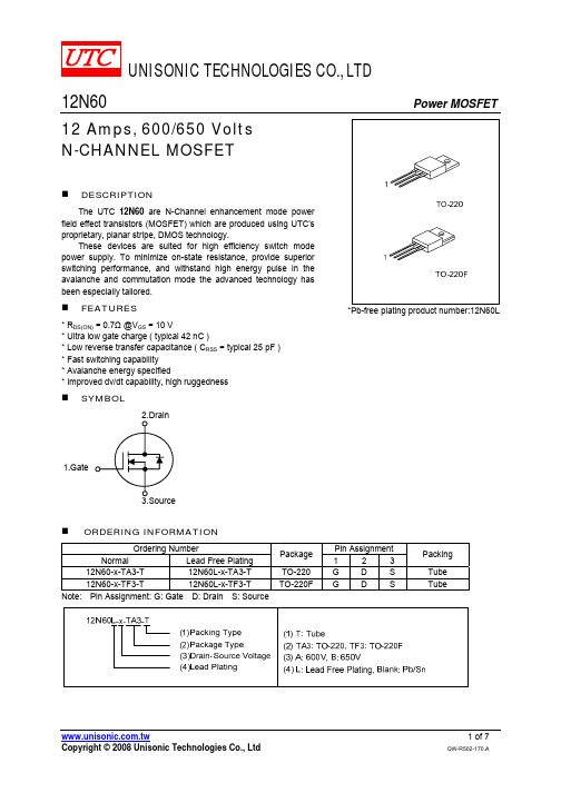
Fig. 3A Gate Charge Test Circuit
Fig. 3B Gate Charge Waveform
10V
RD tp
L VDS
BVDSS IAS
VDD
VDD D.U.T.
ID(t) tp
VDS(t) Time
Fig. 4A Unclamped Inductive Switching Test Circuit Fig. 4B Unclamped Inductive Switching Waveforms
25℃ 100
55℃
10-1 2
Notes:
1.VDS=50V 2.250μs Pulse Test
4
6
8
10
Gate-Source Voltage, VGS (V)
UNISONIC TECHNOLOGIES CO., LTD
12N60-x-TF3-T
12N60L-x-TF3-T
Note: Pin Assignment: G: Gate D: Drain S: Source
Package
TO-220 TO-220F
Pin Assignment
1
2
3
G
D
S
G
D
S
Packing
Tube Tube
Copyright © 2008 Unisonic Technologies Co., Ltd
Turn-On Rise Time Turn-Off Delay Time
tR tD(OFF)
VDD = 300V, ID = 12A, RG = 25Ω (Note 4, 5)
115 240 nsቤተ መጻሕፍቲ ባይዱ95 200 ns
- 1、下载文档前请自行甄别文档内容的完整性,平台不提供额外的编辑、内容补充、找答案等附加服务。
- 2、"仅部分预览"的文档,不可在线预览部分如存在完整性等问题,可反馈申请退款(可完整预览的文档不适用该条件!)。
- 3、如文档侵犯您的权益,请联系客服反馈,我们会尽快为您处理(人工客服工作时间:9:00-18:30)。
2-2
1.5 2.49
1.25 K/W 0.25 K/W
© 2000 IXYS All rights reserved
IXYS MOSFETS and IGBTs are covered by one or more of the following U.S. patents: 4,835,592 4,881,106 5,017,508 5,049,961 5,187,117 5,486,715 4,850,072 4,931,844 5,034,796 5,063,307 5,237,481 5,381,025
BVCES VGE(th) ICES IGES VCE(sat)
IC IC
= 250 mA, VGE = 0 V = 250 mA, VGE = VGE
VCE = 0.8 • VCES VGE = 0 V VCE = 0 V, VGE = ±20 V IC = ICE90, VGE = 15 V
IXYS reserves the right to change limits, test conditions, and dimensions.
Dim. Millimeter Min. Max. A B C D E F G H J K L M N 19.81 20.32 20.80 21.46 15.75 16.26 3.55 3.65 4.32 5.49 5.4 6.2 1.65 2.13 4.5 1.0 1.4 10.8 11.0 4.7 0.4 5.3 0.8 Inches Min. Max. 0.780 0.800 0.819 0.845 0.610 0.640 0.140 0.144 0.170 0.216 0.212 0.244 0.065 0.084 0.177 0.040 0.055 0.426 0.433 0.185 0.209 0.016 0.031 0.087 0.102
Test Conditions T J = 25°C to 150°C T J = 25°C to 150°C; RGE = 1 MW Continuous Transient TC = 25°C TC = 90°C TC = 25°C, 1 ms VGE = 15 V, TVJ = 125°C, RG = 33 W Clamped inductive load, L = 300 mH TC = 25°C
C = Collector, TAB = Collector
Mounting torque with screw M3 Mounting torque with screw M3.5
0.45/4 Nm/lb.in. 0.55/5 Nm/lb.in. 6 300 g °C Features • Very high frequency IGBT • New generation HDMOSTM process • International standard package JEDEC TO-247 • High peak current handling capability Applications • • • • PFC circuit AC motor speed control DC servo and robot drives Switch-mode and resonant-mode power supplies • High power audio amplifiers Advantages • Fast switching speed • High power density
Maximum lead temperature for soldering 1.6 mm (0.062 in.) from case for 10 s
Symbol
Test Conditions
Characteristic Values (TJ = 25°C, unless otherwise specified) min. typ. max. 600 2.5 TJ = 25°C TJ = 125°C 5.0 200 1.5 ±100 2.1 2.7 V V mA mA nA V
元器件交易网
HiPerFASTTM IGBT LightspeedTM Series
IXGH 12N60C
VCES IC25 VCE(sat) tfi(typ)
= 600 V = 24 A = 2.1 V = 55 ns
Symbol VCES VCGR VGES VGEM IC25 IC90 ICM SSOA (RBSOA) PC TJ TJM Ts (5/99)
© 2000 IXYS All rights reserved
1-2
元器件交易网
IXGH 12N60C
Symbol Test Conditions Characteristic Values (TJ = 25°C, unless otherwise specified) min. typ. max. 5 11 860 VCE = 25 V, VGE = 0 V, f = 1 MHz 64 15 32 IC = IC90, VGE = 15 V, VCE = 0.5 VCES 10 10 Inductive load, TJ = 25°C IC = IC90, VGE = 15 V, L = 300 mH VCE = 0.8 • VCES, RG = Roff = 18 W Remarks: Switching times may increase for VCE (Clamp) > 0.8 • VCES, higher TJ or increased RG Inductive load, TJ = 125°C IC = IC90, VGE = 15 V, L = 300 mH VCE = 0.8 • VCES, RG = Roff = 18 W Remarks: Switching times may increase for VCE (Clamp) > 0.8 • VCES, higher TJ or increased RG 20 20 60 55 0.09 20 20 0.15 85 85 0.27 180 180 0.60 S pF pF pF nC nC nC ns ns ns ns mJ ns ns mJ ns ns mJ
Maximum Ratings 600 600 ±20 ±30 24 12 48 ICM = 24 @ 0.8 VCES 100 -55 ... +150 150 -55 ... +150 V V V V A A A A W °C °C °C
TO-247
C (TAB) G C E
G = Gate, E = Emitter,
TO-247 AD (IXGH) Outline
gfs C ies Coes C res Qg Qge Qgc td(on) t ri td(off) tfi Eoff td(on) t ri Eon td(off) tfi Eoff RthJC RthCK
IC = IC90; VCE = 10 V, Pulse test, t £ 300 ms, duty cycle £ 2 %