ISE2008D_产品规格书v3.3
20140121_SHIHLIN_DU08、DU09简易说明书 V1.02
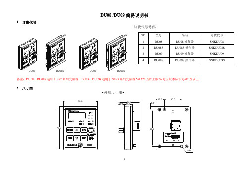
DU08 /DU09简易说明书1.订货代号订货代号说明:DU08SDU08DU09DU09S备注:DU08、DU08S适用于SS2系列变频器,DU09、DU09S适用于SF-G系列变频器V0.320及以上版本(对应版本标识为-02及以上)。
2.尺寸图<外形尺寸图><盘面安装开孔尺寸图> <法兰式安装开孔尺寸图(注)>-注:法兰式安装时,固定安装底座非标配,需另外购买,订货代号:SNKDUMH02(DU08S、DU09S已包含此固定安装底座)。
3.CBL:数据传输线(配合以上操作器使用,非标配,需额外购买):4. 基本操作4.1 操作模式切换流程 4.2工作模式切换流程模式」下,操作键盘显示屏显示「外部模式」下,操作键盘显示屏显示,指示灯,指示灯时,操作模式固定不变,因此没有操作V A EXT REVEXT EXT MONEXT REVMONEXT REVMONEXT REV MON EXT REV EXT REV EXT EXT4.3监视模式下的操作流程图以PU模式为例:异警状态显示输出频率显示输出电压显示输出电流(注1)1.「监视输出频率」,指示灯、与会亮,显示屏显示当时的输出频率。
2.「监视输出电流」,指示灯、与会亮,显示屏显示当时的输出电流值。
3.「监视输出电压」,指示灯、与会亮,显示屏显示当时的输出电压值。
4.「浏览异警纪录」,指示灯与会亮,显示屏显示异警代码。
(注2) 异警代码,请参考士林电机各系列变频器使用说明书。
4.4 频率设定模式的操作流程图 4.5 参数设定模式操作流程 以PU 模式为例:注:参数设定模式下,指示灯调出原有目标频率调整岀新的目标频率EXT REVMONMONEXT EXT REVMONEXT EXT REVMONEXT REVMONEXT REVMON4.6 HELP 模式的操作流程图EXT REVMONEXT REVMONEXT REVMONEXT REVEXTEXT EXTEXT REVEXT EXT REVMONEXT EXTEXT REV4.7 参数拷贝功能(Pr.CP, Pr.CA)Pr.CP “参数拷贝读出”Pr.CA “参数拷贝写入”● 参数拷贝功能在马达停止,P.77=0且PU模式时才有效。
DICE-2008PCID 调试文档

方波:D0832_F.ASM
锯齿波:D0832_C.ASM
阶梯波:D0832_J.ASM
(3)用示波器观察AOUTa及AUOTb的波形。
运行其中一个程序即可。
B
0809
ADC0809 A/D模数转换实验模块:
(1)实验连线:
• AD0809实验区IN0连接电位器的DCOUT1。
(1)8255实验区PC0连接串并转换显示电路CLK;
(2)8255实验区PC1连接串并转换显示电路DIN.
D74ls164.asm
实验源程序一)实验连线:
•逻辑电路区74LS74(D,SET)连接+5V
•逻辑电路区74LS74(Q)连接逻辑电平区L0
•译码电路的74LS138 0000H连接逻辑电路区74LS74(CLK)
直流电机单元:CH0接K6,CH1接K7,DJ接K0.
CH0=1,CH1=0,DJ=1正转
CH0=0,CH1=1,DJ=1反转
5
继电器
继电器单元:JIN接K0。
JIN=0时,JZ和JB导通;
JIN=1时,JZ和JK导通.
用万用表二极管档测量。
6
门电路
与、或、非门,用开关和LED发光二极管测试:
与门:A1=0,B1=0,Y1=0
•译码电路的74LS138 0030H连接逻辑电路区74LS74(CLR)
(2)参考程序:D74LS138.ASM在PCI组合窗口下装入、编译、链接实验程序;并运行该程序。
(3)观察发光二极管的变化。
实验源程序一
A
0832
D/A0832转换实验单元:
(1)实验电路:无须连线。
EM DE08 数字量扩展模块 用户手册说明书

EM DE08数字量扩展模块
用户手册
版本:V2.01
发布日期:06/2021
大连德嘉工控设备有限公司
目录
1.产品概述 (3)
2.参数设置 (5)
1产品概述
所有SMART200系列数字量扩展模块接口均与原装模块一致,使用及配置方式也与原装模块一致,可直接替换原装模块使用,可搭配西门子SMART SR/ST系列CPU使用。
完美兼容:兼容西门子Smart扩展模块。
尺寸W x H x D(mm):45x100x81
数字量扩展模块产品选型
型号订货号描述
EM DE086WB7288-2DE08-0AA08点数字量输入
EM DE166WB7288-2DE16-0AA016点数字量输入
EM DT086WB7288-2DT08-0AA08点数字量输出
EM DR086WB7288-2DR08-0AA08点数字量输出(继电器)
EM QT166WB7288-2QT16-0AA016点数字量输出
EM QR166WB7288-2QR16-0AA016点数字量输出(继电器)
EM DT166WB7288-2DT16-0AA08点数字量输入/8点数字量输出
EM DR166WB7288-2DR16-0AA08点数字量输入/8点数字量输出(继电器)EM DT326WB7288-2DT32-0AA016点数字量输入/16点数字量输出
EM DR326WB7288-2DR32-0AA016点数字量输入/16点数字量输出(继电器)
2参数设置I/O接线图。
ISE2016D_产品规格书v3.4

0.9 kg 无风扇散热 导轨、壁挂(可选套件) 35 年 24VDC(12~36VDC),支持冗余输入 7 针可插拔螺丝接线端子 提供 提供 <7.2w -40 ~ +85 °C -40 ~ +85 °C 5%~95% (无凝露) <10us 3.2Gbps 8k 1Mbit IEEE 802.3 适用于 10Base-T
� 简单易用的功能设计
1/4
� �
即插即用,快速部署 数据线性转发,保证实时性 � � � � � 支持工业 DIN 导轨安装方式,可选配壁挂套件,满足不同场景部署需求 支持通过硬件拨码开启/关闭广播风暴保护、流控和端口连接中断告警,简单易用 提供 1 路报警输出接口,利于及时排查隐患,确保业务数据的可持续性 支持 IEEE 802.3 x 流控,背压式流控,保证数据完整性 转发固有延时<4us,满足工业生产数据实时性需求
产品规格
项目 RJ45 电口 接口 FX 光口 LED 指示灯 外壳包装 尺寸(WxHxD) 机械结构 重量 散热方式 安装方式 MTBF 输入电压 接口端子 电源 过载保护 反接保护 功耗 操作温度 工作环境 存储温度 相对湿度 转发固有延时 交换性能 交换带宽 MAC 地址表 数据包缓冲区 ISE2016D 10/100Base-T(X) RJ45 电口,支持全/半双工和 MDI/MDI-X 自适应 100Base-FX 端口(SC/ST/FC 接口) PWR1,PWR2,STAT,FAULT,FX(光口) IP40 防护等级,全封闭无缝式金属外壳,可涂 PCB 保护涂层 75mm x 132.6mm x 113mm
以太Байду номын сангаас标准 功能特性
IEEE 802.3u 适用于 100Base-T(X)和 100Base-FX IEEE 802.3x 适用于流量控制
西安精科D2008 型 电子称重仪表 使用说明书

D2008型电子称重仪表使用说明书2022年3月版●使用前请仔细阅读本产品说明书●请妥善保管本产品说明书,以备查阅目录第一章技术参数 (1)第二章常规操作说明 (2)一、开机及开机自动置零 (2)二、手动置零 (2)三、去皮 (2)四、清皮 (2)五、日期与时间查询与设置 (2)第三章称重记录的储存与打印 (2)一.称重记录的储存 (2)二.车号皮重的设置与清除方法: (3)三、车号皮重的批量查看与清除方法: (3)四.称重记录的打印 (3)五.明细报表打印 (4)六.称重记录的查询与清除 (4)七.称重记录和车号皮重的全部删除操作 (5)八.查询打印 (5)第四章信息提示 (5)附录A:打印操作举例: (6)附录B:明细表及统计报表示例 (7)▲仪表电源接地线必须符合电气安全规定,接线盒、传感器的外壳必须接地良好。
▲数字传感器与仪表的连接必须可靠,数字传感器的屏蔽线必须可靠接地。
▲在仪表通电状态下,所有连接线不允许进行插拔,防止静电和漏电损坏仪表或传感器。
▲传感器和仪表都是静电敏感设备,在使用中必须切实采取防静电措施。
▲在雷雨季节,系统必须落实可靠的避雷措施,防止因雷击造成传感器和仪表的损坏,确保操作人员的人身安全和称重设备及相关设备的安全运行。
▲不得在有可燃性气体或可燃性蒸汽的场合使用,不得在有压力的罐装系统中使用。
▲仪表和传感器须远离强电场强磁场,远离强腐蚀性物体,远离易燃易爆物品。
▲严禁使用强溶剂(如:苯、硝基类油)清洗机壳。
▲不得将液体或其他导电颗粒注入仪表内,以防仪表损坏和触电。
▲本产品非经技术监督部门授权,不得擅自开启铅封,不破坏铅封不能标定。
◆为保证仪表显示清晰和使用寿命,仪表不宜放在阳光直射下使用,放置地点应较平整。
◆仪表不宜放在粉尘及振动严重的地方使用,避免在潮湿的环境中使用。
◆在插拔仪表与外部设备连接线前,必须先切断仪表及相应设备电源。
◆仪表对外接口须严格按使用说明书中所标注的方法使用,不得擅自更改连接。
D R I L L S 2001年版商品目录说明书

D R I L L S2001N O T E SiI N D E XFractional Sizes,118°Point,Surface Treated . . . . . . . . . . . . . . . .1600 . . . . .1Fractional Diameters,118°Point,Bright .1600 . . . . .1Fractional Diameters,118°Point,TiN Coated . . . . . . . . . . . . . . . . . . . .1600 . . . . .1Wire Sizes,118°Point,Surface Treated .1601 . . . . .2Wire Sizes,118°Point,Bright . . . . . . . .1601 . . . . .2Wire Sizes,118°Point,TiN Coated . . . . .1601 . . . . .2Letter Sizes,118°Point,Surface Treated .1602 . . . . .3Letter Sizes,118°Point,Bright . . . . . . .1602 . . . . .3Letter Sizes,118°Point,TiN Coated . . . .1602 . . . . .3Metric Sizes,118°Point,Surface Treated 1603 . . . .4–6Metric Sizes,118°Point,Bright . . . . . . .1603 . . . .4–6J O B B E R S L E N G T H , H E A V Y D U T YHigh Speed SteelFractional Sizes,135°Split Point,Surface Treated . . . . . . . . . . . . . . . .1604 . . . . .7Fractional Diameters,135°Split Point,TiN Coated . . . . . . . . . . . . . . . . . . . .1604 . . . . .7Wire Sizes,135°Split Point,Surface Treated . . . . . . . . . . . . . . . .1605 . . . . .8Wire Sizes,135°Split Point,TiN Coated .1605 . . . . .8Letter Sizes,135°Split Point,Surface Treated . . . . . . . . . . . . . . . .1605-A . . . .9Letters Sizes,135°Split TiN Coated . . .1605-A . . . .9CobaltFractional Sizes,135°Split Point,Surface Treated . . . . . . . . . . . . . . . .1606 . . . .10Wire Sizes,135°Split Point,Surface Treated . . . . . . . . . . . . . . . .1607 . . . .11Letter Sizes,135°Split Point,Surface Treated . . . . . . . . . . . . . . . .1608 . . . .12Fractional Sizes,118°Point,Surface Treated . . . . . . . . . . . . . . . .1609 . . .13–14Fractional Sizes,118°Point,Bright . . . . .1609 . . .13–14Wire Sizes,118°Point,Surface Treated .1610 . . . .15Letter Sizes,118°Point,Bright . . . . . . .1611 . . . .16S C R E W M A C H I N E L E N G T H S , H E A V Y D U T YHigh Speed SteelFractional Sizes,135°Split Point,Surface Treated . . . . . . . . . . . . . . . .1612 . . . .17Fractional Sizes,135°Split Point,TiN Coated . . . . . . . . . . . . . . . . . . . .1612 . . . .17Wire Sizes,135°Split Point,Surface Treated . . . . . . . . . . . . . . . .1613 . . . .18Wire Sizes,135°Split Point,TiN Coated .1613 . . . .18Letter Sizes,135°Split Point,Surface Treated . . . . . . . . . . . . . . . .1614 . . . .19CobaltFractional Sizes,135°Split Point,Surface Treated . . . . . . . . . . . . . . . .1615 . . . .20Wire Sizes,135°Split Point,Surface Treated . . . . . . . . . . . . . . . .1616 . . . .21Letter Sizes,135°Split Point,Surface Treated . . . . . . . . . . . . . . . .1617. . . .22R E D U C E D S H A N KHigh Speed Steel1/2" Round Shank S &D,118°Point,Surface Treated . . . . . . . . . . . . . . . .1618 . . . .23S E T SDrill Sets . . . . . . . . . . . . . . . . . . . . . . . . .1619 . . .24–25LIST STYLENO.PAGE Drill Feeds And Speeds . . . . . . . . . . . . . . . . . . . . . . . .30Trouble Shooting Guide . . . . . . . . . . . . . . . . . . . . . . . .31Tap Drill Sizes For Metric Screw Threads . . . . . . . . . . .34Hardness Conversion Table . . . . . . . . . . . . . . . . . . . . .35LIST STYLENO.PAGEI N D E XSurface TreatedTiN Coatedii1J O B B E R S L E N G T H , H I G H S P E E D S T E E LG E N E R A L P U R P O S E , J O B B E R S L E N G T H D R I L L118°P o i n t , S u r f a c e T r e a t e d , B r i g h t , o r T i N C o a t e dG E N E R A L F E A T U R E S A N D A P P L I C A T I O N SDesigned for portable and machine drilling in a broad range of steel,ferrous and non-ferrous materials (bright finish in non-ferrous),under many different conditions.TiN coating with increased surface hardness allows for extended tool life,greater lubricity,betterchip ejection,increased productivity,and lower horsepower requirements.J O B B E R S L E N G T H , H I G H S P E E D S T E E L2J O B B E R S L E N G T H , H I G H S P E E D S T E E L3L e t t e r S i z e sG e n e r a l P u r p o s e , 118°P o i n tP A C K A G I N GA to N — 12 per package O to Z — 6 per packageEDP NO.EDP NO.J O B B E R S L E N G T H , H I G H S P E E D S T E E L4c o n t i n u e dM E T R I C , J O B B E R S L E N G T H D R I L L118°P o i n t (M a n u f a c t u r e d t o D I N S t a n d a r d s ),B r i g h t F i n i s h t o .50, S u r f a c e T r e a t e d .55 a n d L a r g e rG E N E R A L F E A T U R E S A N D A P P L I C A T I O N SDesigned for portable and machine drilling in a broad range of steel,ferrous and non-ferrous materials (bright finish in non-ferrous),under many different conditions.TiN coating with increased surface hardness allows for extended tool life,greater lubricity,better chip ejection,increased productivity,and lower horsepower requirements.J O B B E R S L E N G T H , H I G H S P E E D S T E E L5c o n t i n u ed Me t r i c S i z e sG e n e r a l P u r p o s e , 118°P o i n tFLUTE LENGTHOVERALL LENGTH EDP NO.c o n t i n u ed FLUTE LENGTH OVERALL LENGTH EDP NO.c o n t i n u e dJ O B B E R S L E N G T H , H I G H S P E E D S T E E L6J O B B E R S L E N G T H , H I G H S P E E D S T E E LM E D I U M D U T Y , J O B B E R S L E N G T H D R I L L135°S p l i t P o i n t , S u r f a c e T r e a t e d o r T i N C o a t e dG E N E R A L F E A T U R E S A N D A P P L I C A T I O N SMedium duty aircraft type B drills are designed for more demanding applications.The 135°split point is self-centering,reduces thrust is quick start-ing and highly accurate.ideal for portable or machine drilling of low tensile strength alloy material and stainless steels.TiN coating with increased surface hardness allows for extended tool life,greater lubricity,better chip ejection,increased productivity,and lower horsepower requirements.J O B B E R S L E N G T H,H I G H S P E E D S T E E LJ O B B E R S L E N G T H,H I G H S P E E D S T E E LH E A V Y D U T Y,J O B B E R S L E N G T H D R I L L135°S p l i t P o i n t,S t r a w F i n i s hG E N E R A L F E A T U R E S A N D A P P L I C A T I O N SHeavy duty aircraft type J drills are designed for tough,high tensile strength materials such as PH stainless steel, titanium,and inconel.The heat resistant cobalt material in combination with the 135°degree self-centering split point reduces thrust,is quick starting and highly accurate.Ideal for machine drilling.J O B B E R S L E N G T H,C O B A L T H I G H S P E E D S T E E LS C R E W M A C H I N E L E N G T H , H I G H S P E E D S T E E Lc o n t i n u e dG E N E R A L P U R P O S E , S C R E W M A C H I N E L E N G T H D R I L L H i g h S p e e d S t e e l , 118°P o i n t , S u r f a c e T r e a t e dG E N E R A L F E A T U R E S A N D A P P L I C A T I O N SPrimarily used in screw machines.Shorter flute and overall length provides increase rigidity in machine drilling resulting in lessdeflection,increased tool life,and better hole accuracy.Designed to drill in a wide variety of low tensile strength materials.S C R E W M A C H I N E L E N G T H,H I G H S P E E D S T E E LS C R E W M A C H I N E L E N G T H,H I G H S P E E D S T E E LS C R E W M A C H I N E L E N G T H,H I G H S P E E D S T E E LS C R E W M A C H I N E L E N G T H , H I G H S P E E D S T E E LH E A V Y D U T Y , S C R E W M A C H I N E L E N G T H D R I L L 135°S p l i t P o i n t , S u r f a c e T r e a t e d o r T i N C o a t e dG E N E R A L F E A T U R E S A N D A P P L I C A T I O N SHeavy duty,aircraft type C drills are ideal for portable drilling.The 135°split point is self-centering,reduces thrust,and is quick starting.The short rugged constructions performs will in a broad range of materials in the iron and steel families.TiN coating with increased surface hardness allowsfor extended tool life,greater lubricity,better chip ejection,increased productivity,and lower horsepower requirements.S C R E W M A C H I N E L E N G T H,H I G H S P E E D S T E E LS C R E W M A C H I N E L E N G T H,H I G H S P E E D S T E E LS C R E W M A C H I N E L E N G T H,C O B A L T H I G H S P E E D S T E E Lrugged construction performs well in a broad range of materials especially high alloys and work hardened material.T5F r a c t i o n a l S i z e sH e a v y D u t y,135°S p l i t P o i n tP A C K A G I N G1/16 to 19/64 — 12 per envelope5/16 to 1/2 — 6 per envelopeEDP NO.SIZE EQUIV.LENGTH LENGTH FINISH1/16.06255/81-5/8687005/64.078111/161-11/16687013/32.09383/41-3/4687027/64.109413/161-13/16687031/8.12507/81-7/8687049/64.140615/161-15/1668705S C R E W M A C H I N E L E N G T H,C O B A L T H I G H S P E E D S T E E LS C R E W M A C H I N E L E N G T H,C O B A L T H I G H S P E E D S T E E LR E D U C E D S H A N K D R I L L S , H I G H S P E E D S T E E L1/2 RO U N D S H A N K S & D D R I L L , R E D U C E D S H A N K D R I L LH i g h S p e e d S t e e l , 118°P o i n t , S u r f a c e T r e a t e dG E N E R A L F E A T U R E S A N D A P P L I C A T I O N SFor use in a 1/2" diameter portable drill chuck.Precision ground for a high degree of concentricity between the shank and body diameter.Ideal for drilling in low and medium tensile mon flute and overall lengths allow for minimal adjustment during tool change.S E T S118°J O B B E R S L E N G T H,G E N E R A L P U R P O S E,H I G H S P E E D S T E E L118°M E T R I C J O B B E R S L E N G T H,G E N E R A L P U R P O S E,H I G H S P E E D S T E E LS E T S135°M E D I U M D U T Y , J O B B E R S L E N G T H , H I G H S P E E D S T E E L135°H E A V Y D U T Y , J O B B E R S L E N G T H , C O B A L T H I G H S P E E D S T E E LS E T S118°G E N E R A L P U R P O S E,S C R E W M A C H I N E L E N G T H,H I G H S P E E D S T E E L135°M E D I U M D U T Y,S C R E W M A C H I N E L E N G T H,H I G H S P E E D S T E E L135°H E A V Y D U T Y,S C R E W M A C H I N E L E N G T H,C O B A L T H I G H S P E E D S T E E LS E T S27118°1/2 R E D U C E D S H A N K , H I G H S P E E D S T E E LT E C H N I C A L I N F O R M A T I O N28D RI L L N O M E N C L A T U R EAxis – The imaginary straight line which forms the longitudinal center line of the drill.Back Taper – A slight decrease in diameter from front to back in the body of the drill.Body – The portion of the drill extending from the shank or neck to the outer corners of the cutting lips.Body Diameter Clearance – That portion of the land that has been cut away so it will not rub against the walls of the hole.Chisel Edge – The edge at the end of the web that connects the cut-ting lips.Chisel Edge Angle – The angle included between the chisel edge and the cutting lip,as viewed from the end of the drill.Clearance – The space provided to eliminate undesirable contact between the drill and the workpiece.Clearance Diameter – The diameter over the cut away portion of the drill lands.Drill Diameter – The diameter over the margins of the drill measured at the point.Flutes – Helical or straight grooves in the body of the drill to provide cutting lips,permit removal of chips and allow coolant to reach the cutting lips.Flute Length – The length from the outer corners of the cutting lips to the extreme back end of the flutes.Helix Angle – The angel made by the leading edge of the land with a plane containing the axis of the drill.Land – the peripheral portion of the body between adjacent nd Width – The distance between the leading edge and the heel of the land measured at a right angle to the leading edge.Lead – The axial advance of the leading edge of the land in one turnaround the circumference.Lips – The cutting edges of a two-flute drill extending from the chisel edge to the periphery.Lip Relief – The axial relief angle at the outer corner of the lip.It is measured by projection into a plane,tangent to the periphery,at the outer corner of the lip.Margin – The cylindrical portion of the land which is not cut away to provide clearance.Overall Length – The length from the extreme end of the shank to the outer corners of the cutting lips.It does not include the conical shank end,often used on straight shank drills,or the conical cutting point.Point – The cutting end of a drill,made up of the ends of the lands and the web.In form it resembles a cone but departs from a true cone to furnish clearance behind the cutting lips.Point Angle – The angle included between the cutting lips,projected upon a plane parallel to the drill axis and parallel to the two cutting lips.Relative Lip Height – The difference in indicator reading between the cutting lips of the drill.It is measured at a right angle to the cutting lip at a specific distance from the axis of the drill.Relief –The result of the removal of tool material behind the cutting lip and leading edge of the land to provide clearance and prevent rub-bing.Web – The central portion of the body that joins the lands.The extreme end of the web forms the chisel edge on a two-flute drill.Web Thickness – The thickness of the web at the point,unless anoth-er specific location is specified.Web Thinning – The operation of reducing the web thickness,at the point,to reduce drilling thrust.T E C H N I C A L I N F O R M A T I O NS P E E D S F O R D R I L L I N GCUTTING POINTSPEED POINT ANGLEMATERIAL BEING DRILLED(SFM)STYLE(DEGREES)FEED RATE Aluminum Alloys200-300Conventional118Medium to Heavy Magnesium Alloys200-300Conventional118Medium to Heavy Brass and Bronze75-150Conventional118Medium to Heavy Cast IronSoft75-125Conv.or Split118 or 135Medium to Heavy Medium Hard50-100Conv.or Split118 or 135MediumHard Chilled10-20Conventional118Light to Medium Malleable75-125Conv.or Split118 or 135MediumSteelMild,.2 to .3 Carbon50-100Conventional118Medium to Heavy Medium,.4 to .5 Carbon45-80Conventional118MediumTool,1.2 Carbon40-60Conventional118MediumForgings40-60Conventional118MediumAlloy,300 to 400 BHN20-30Conv.or Split118 or 135MediumHigh TensileRc 35-4030-40Conv.or Split118 or 135MediumRc 40-4525-35Conv.or Split118 or 135MediumRc 45-5015-25Conv.or Split118 or 135Light to Medium Rc 50-557-15Conv.or Split118 or 135Light to Medium Maraging,Heat Treated7-20Conv.or Split118 or 135MediumMaraging,Annealed40-55Conv.or Split118 or 135Light to Medium Titanium AlloysCommercially Pure50-60Heavy Duty Split135Medium5AI-2Sn,8Al-1 Mo-1V20-45Heavy Duty Split135Medium2Fe-2Cr-Mo Annealed6Al-4V,4Al-4Mn,7Al-4Mo20-35Heavy Duty Split135Medium5Al-2Sn,8Al-1Mo-1V15-20Heavy Duty Split135Medium2Fe-2Cr-Mo SolutionTreated and AgedHigh Temperature AlloysCobalt Base,HS25,S816,V367-20Heavy Duty Split135MediumINCO 800,A286,N1557-20Heavy Duty Split135MediumNickel Base,Inconel 700,5-15Heavy Duty Split135MediumU500,Rene 41Monel Metal30-50Heavy Duty Split135Medium Stainless SteelFree Machining,303,416,42030-100Heavy Duty Split135MediumAustenitic,300 Series20-60Heavy Duty Split135MediumFerritic,400 Series20-60Heavy Duty Split135MediumMartensitic,Heat Treated10-30Heavy Duty Split135MediumPlastics and Related Materials100-200Low Angle90Medium to Heavy Zinc Alloys150-250Conventional118Medium to Heavy The speeds shown are for average conditions where coolant can be efficiently applied.Where the strength of the drill is not a critical factor and where the workpiece can be rigidly supported.When one or more of these conditions vary,the speeds must be adjusted accordingly.29T E C H N I C A L I N F O R M A T I O N30F E E D R A T E P E R R E V O L U T I O N F O R D R I L L SDRILL DIAMETER FEED PER REVOLUTIONRANGELIGHTMEDIUMHEAVY1/16 Thru 1/8.0005–.0010.0010–.0020.0020–.0030Over 1/8 Thru 1/4.0010–.0030.0030–.0050.0050–.0070Over 1/4 Thru 1/2.0030–.0050.0050–.0070.0070–.0090Over 1/2 Thru 3/4.0050–.0080.0080–.0110.0110–.0140Over 3/4 Thru 1.0080–.0110.0110–.0140.0140–.0170Over 1.0120–.0150.0150–.0200.0200–.0250The feed rates shown are for average conditions where coolant can be efficiently applied,where the strength of the drill is not a critical factor and where the workpiece can be rigidly supported.When one or more of these conditions vary; the feeds must be adjusted accordingly.S P E E D S A N D F E E D S F O R D E E P H O L E D R I L L I N GHoles which must be drilled three or more diameters deep fall into the “Deep Hole”drilling class and some adjustment of speeds and feeds is necessary.The deeper the hole,the greater the tendency for chip to pack and clog the flutes of the drill.This increases the amount of heat generated and prevents coolant from reaching the drill points.Heat buildup will eventually result in premature failure.Step drilling,that is,drilling a short distance and then retracting the drill,will often reduce the chip packing.The deeper the hole the more often the drill must be retracted.A reduction in speed and feed to reduce the amount of heat generated is generally required in most deep-hole applications where coolant cannot be effectively applied.S P E E D A N D F E E D R E D U C T I O N P E R C E N T A G E S F O R D E E P H O L E D R I L L I N GREDUCE REDUCE HOLE DEPTHSPEED BYFEED BY3 x Drill Diameter 10%10%4 x Drill Diameter 20%10%5 x Drill Diameter 30%20%6 x Drill Diameter 40%20%S P E E D C A L C U L A T I O N S F O R D R I L L I N GSurface Feet Per Minute (SFM) = .26 X RPM X Drill DiameterRevolutions Per Minute (RPM) =SFMDrill DiameterT E C H N I C A L I N F O R M A T I O NT R O U B L E S H O O T I N G G U I D E F O R D R I L L SPROBLEM PROBABLY CAUSESCorners break down.Cutting speed too high.Hard spots in material.Insufficient coolant at drill point.Flutes clogged with chips.Cutting lips chip.Too much feed.Lip relief too great.Margin chips.Oversize drill bushing.Drill breaks.Point improperly ground.Too much feed.Drill is dull.Flutes clogged with chips.Tang breaks.Imperfect fit between taper shank and socket caused by dirt or chips.Socket is burredor badly worn.Drill splits up center.Not enough lip relief.Too much feed.Drill will not enter work.Drill is dull.Not enough lip relief.Web is too heavy.Surface of hole is rough.Point improperly ground or dull.Insufficient coolant at drill point.Too much feed.Workholding device not rigid.Hole is oversize.Unequal point angles.Unequal length of cutting edges.Machine spindle bearings may be worn.Chip shape changes while drilling.Drill is dull.Cutting lips are chipped.Large chip coming out of one flute,Point is improperly ground and one lip is doing all of the cutting.small chip coming out of the other.31T E C H N I C A L I N F O R M A T I O N32T E C H N I C A L I N F O R M A T I O Ndrilled.The actual percent of thread engagement may be determined by pin gaging the hole.33T E C H N I C A L I N F O R M A T I O NT A P D R I L L S I Z E S F O R M E T R I C S C R E W T H R E A D S34T E C H N I C A L I N F O R M A T I O N35H A R D N E S S C O N V E R S I O N T A B L EROCKWELL HARDNESS TENSILE BRINELL STRENGTH CBAHARNESS(PSI)70–86.6––69–86.1––68–85.6––67–85.0––66–84.5––65–83.9––64–83.4––63–82.8––62–82.3––61–81.8––50–81.2–314,00059–80.7–306,00058–80.1–299,00057–79.6–291,00056–79.0–284,00055–78.5–277,00054–78.0–270,00053–77.4–263,00052–76.8500256,00051–76.3487250,00050–75.9475243,00049–75.2464236,00048–74.7451230,00047–74.1442223,00046–73.6432217,00045–73.1421211,00044–72.5409205,00043–72.0400199,000ROCKWELL HARDNESS TENSILE BRINELL STRENGTH CBAHARNESS(PSI)42–71.5390194,00041–70.9381188,00040–70.4371182,00039–69.9362176,00038–69.4353171,00037–68.9344166,00036–68.4336162,00035–67.9327157,00034–67.4319153,00033–66.8311149,00032–66.3301144,00031106.065.8294140,00030105.565.3286136,00029104.564.7279132,00028104.064.3271129,00027103.063.8264126,00026102.563.3271123,00025101.562.8253120,00024101.062.4247117,00023100.062.0243114,0002299.061.5237112,0002198.561.0231110,0002098.060.5226108,0001796.059.0215–1594,057.5204–1292.056.5194–990.055.0184–A Talbots Holdings Company200 Front Street Millersburg, Pennsylvania 17061 800-682-8832Fax: 717-692-270762-23047。
风电场组网解决方案

风电场组网解决方案
链接:/tech/17590.html
风电场组网解决方案
风力发电机需在恶劣的环境下长年运行,并要求对运行过程中的任何异常情况均能作出及时反应,因而要保证对其进行实时、可靠的控制。
在风力发电场,通常需要对几十台或上百台风力发电机进行集群监控,要求构建稳定可靠、快速实时的网络系统。
为保障风力发电机的正常运行,期望实现预防式维护,从而大幅度减少风机故障带来的损失,未来还将出现越来越多的风机状态监测与分析,增加视频、状态监测等数据流。
业以太网交换机
具备极高的可靠性,产品通过工业四级电磁兼容性检测,工作温度:-40~85
℃,铝合金外壳无风扇散热技术,IP40防护等级,可涂三防漆,能够在严酷的环境中可靠、稳定地工作。
为保障通信的可靠性,可组成冗余光纤环网,具有快速自愈功能(最大恢复时间5ms/台)。
通信网络出故障时,能够自动平滑的切换到冗余备份线路。
利用千兆光纤网络带宽的优势和QoS功能,高效地支持视频、状态监测、语音等多种形式监测数据的传输。
ISM2008D系列结构精简,适合空间有限的机塔控制箱。
ISM3010D系列管理型以太网交换机提供4个光纤接口,可连接机塔控制箱并和其它风机互连组成千兆冗余环网。
提供批量配置和拓扑自动发现等功能,简化了工程的实施和维护工作。
映翰通基于移动网络的远程通讯方案支持风电场建设阶段的通讯需求。
原文地址:/tech/17590.html
页面 1 / 1。
FDC 产品介绍手册说明书

www.finedisc.co.krPRESSURESAFETY DEVICESRUPTURE DISCEXPLOSION PANELN2 BLANKETING SYSTEMEMERGENCY RELIEF HATCHT heL e a d e r o f S a f e t y E q u i p m e n t04领导致辞06 公司历程07 认证现况08RUPTURE DISC 介绍10KOSHA 义务安全认证12RUPTURE DISC 选择指南13选定 RUPTURE DISC 模型14 计算 RUPTURE DISC 尺寸16产品目录26RUPTURE DISC - 各模型特征32 RUPTURE DISC - ACCESSORY33 EXPLOSION PANEL34N2 BLANKETING SYSTEM35 EMERGENCY RELIEF HATCH专利以及知识产权199120062004199920081995200720002009200220032010韩国Tanktech内成立Rupture Disc事业部门仁济大学产学共同技术开发事业 - 构造Scored Type生产体系Scored Type Rupture Disc国产化成功Fine Disc分公司 - Rupture Disc 专门公司更换法人 - Fine Disc(株)共同研究开发KIMM(韩国机械研究院)和Rupture Disc Test Program 实行中小企业生产环境, 革新技术开发课题构造大型尺寸的Rupture Disc生产体系增加获得45个形式KOSHA安全认证开发Rupture Disc Size Calculation Program ‘推进-持续’火箭推进器开发事业 - 防卫事业厅登录为防护装置制造企业(KOSHA)加入制造物责任保险(PL保险) - 3乙韩币构造ISO 9001:2000 品质认证体系独自开发N 2, Blanketing System开发超微压Rupture Disc‘KS B ISO 6718/4162-2/4162-6’ 参与Rupture Disc规格顾问获得俄罗斯‘GOST’认证增加了6个形式的KOSHA安全认证获得了技术革新型中小企业(INNO-BIZ)认证.增加获得了 14个形式的KOSHA 安全认证名称改为‘FDC(株)’ - FDC Co.,Ltd.设立企业附属研究所获得KOSHA防护装置品质部分优秀奖20台核心部件素材开发事业 - 知识经济部国家政策课题被选为专利明星企业 - 专利厅/商工会议所被指定为输出有望中小企业 - 中小企业厅构造室温试验设备登录证以及认证书Rupture disc 形式认证2. Rupture Disc 的义务安全认证适用范围■ 使用流体的物质特性- Gas or Vapor : 分子量 (Mol weight), 绝热指数(Specific heat ratio), 压缩系数■ 使用流体的状态 : Gas, Vapor, Steam, Liquid 等■ 运转状态 : Static, Pulsation(Oscillation), Cycle 等■ 压力容器的最大允许运转压力(MAWP)■ 最大运转压力及温度■ 要求流量 (Required Capacity)■ Rupture Disc的破裂设置压力及设置温度■ 反压力(Back Pressure)及真空(Vacuum Pressure)■ 材质(Holder/Disc/Accessory)■ Connection(Flange/Fitting)式样■ Rupture Disc 的设置类型 : Primary, Secondary, Combination, External Fire ■ 运转费(Operating Ratio)计算 : 运转费 = 最大运转压力/最少破裂压力 X 100※ 最少破裂压力 = 设置破裂压力 - 负的爆破压力公差STEP 1.压力容器及工程运转式样 Check (Process Data)STEP 2.选定Model 及 AccessorySTEP 3.计算(By FDC)尺寸及额定运转泄放容量(Rated Capacity)发生需要安全装置的情况可以设置安全阀Yes YesYesYesYesNo NoNoNo No设置2个直列 Rupture disc设置2个并列 Rupture discRupture disc与 安全阀直列设置设置1个 Rupture discRUPTURE DISC选择指南RUPTURE DISC选定模型设置Rupture disc是否可以泄露装有的物质为更换Rupture disc 是否可以停业根据运转条件是否对Rupture disc 的寿命有影响压力上升的速度是否很快or 装有的物质是不是有毒物质or 装有的物质是不是腐蚀性物质or 装有的物质是不是高分子物质需要大量排除流量吗?or 压力(低/高压)/温度(低/高温)是不是恶劣条件or 是否担心综合反映表1. 气体(Gas)气的性质表2. 对于背压的容量校正系数表3. 根据粘度的的容量校正系数Reynold’s number1.00.90.80.70.60.50.40.310204060801002004006008001,0002,0004,00010,00020,000100,000RUPTURE DISCSIZINGPRODUCTS LISTKSRRKU KSRSFVKSRSFP KSRSFUKSRSTV KSRSTU KSRRCVF I T T I NG C O N N E C T I O N T Y P EKSRRKPKSRRKU KSRSFVKSRSFP KSRSFUKSRSTV KSRSTPKSRSTU KSRRCVKSRRCP KSRRCUKSRRKV PRODUCTS LISTPRODUCTS LISTKSRRKSRRKSRR KSRRKSRBKHKSRSRKSRSRKSRSRKSRSRKSRBKHKSRBKH KSRBKHKSRRKKSRRKKSRRK KSRRKKSRSFKSRSFKSRSTKSRSTKSRST KSRSTKSRCTKSRCTKSRSFKSRSFKSRCKSRCKSRRCHKSRRCKSRRCFKSRRCFDKSRC KSRCKSRRCHKSRRCHKSRRCFITTING CONNECTION KSROHKSROLKSRRLVCRPLUGUNIONKSROH KSROKSROH KSROFKSROFKSROHDKSROFDKSRORain HoodJunction Box Sensor Disc Jack Screw Stud Bolt & Nut Eye Bolt J-HookGasket Rupture Disc Ass’y with P/G & E.F.V & FittingReducerE.F.V P/G P/S KSRPR(Flat Type)KSBKL KSBKT KSBKSFDC NETWORK阿拉伯联合酋长国韩国台湾泰国新加坡■总公司韩国 庆尚南道 金海市酒村面良洞里 368-13TEL. 055-337-0852 / FAX. 055-337-0858E-mail:********************.kr■分公司韩国 庆尚南道 金海市酒村面内三1122-4www.finedisc.co.kr。
- 1、下载文档前请自行甄别文档内容的完整性,平台不提供额外的编辑、内容补充、找答案等附加服务。
- 2、"仅部分预览"的文档,不可在线预览部分如存在完整性等问题,可反馈申请退款(可完整预览的文档不适用该条件!)。
- 3、如文档侵犯您的权益,请联系客服反馈,我们会尽快为您处理(人工客服工作时间:9:00-18:30)。
2/4
项目 出 最大允许功率:60W 最大允许电压:220V DC 最大允许电流:2A DC 拨码开关
ISE2008D
可通过拨码开启/关闭广播风暴保护、流控和端口连接中断告警。 IEC 61000-4-2(静电) IEC 61000-4-3(辐射电场) 等级 3 等级 3 等级 3 等级 3 等级 3 等级 4
产品规格
项目 RJ45 电口 接口 FX 光口 LED 指示灯 外壳包装 尺寸(WxHxD) 机械结构 重量 散热方式 安装方式 MTBF 输入电压 接口端子 电源 过载保护 反接保护 功耗 操作温度 工作环境 存储温度 相对湿度 转发固有延时 交换性能 交换带宽 MAC 地址表 数据包缓冲区 ISE2008D 10/100Base-T(X) 自适应 RJ45 电口 100Base-FX 端口(SC/ST/FC 接口) PWR1,PWR2,STAT,FAULT,FX(光口) IP40 防护等级,全封闭无缝式金属外壳,可涂 PCB 保护涂层 45mm x 132.6mm x 112mm 0.6 kg 无风扇散热 导轨、壁挂(可选套件) 35 年 24VDC(12~48VDC),支持冗余输入 7 针可插拔螺丝接线端子 提供 提供 <5.1W -40 ~ +85 °C -40 ~ +85 °C 5%~95% (无凝露) <4us 1.6Gbps 8k 1Mbit IEEE 802.3 适用于 10Base-T 以太网标准 功能特性 端口流控 继电器报警输 IEEE 802.3u 适用于 100Base-T(X)和 100Base-FX IEEE 802.3x 适用于流量控制 支持 IEEE 802.3 x 流控,背压式流控,可通过拨码开关开启/关闭流控。 额定控制容量:2A@30V DC
电磁兼容性 工业标准
IEC 61000-4-4(脉冲群) IEC 61000-4-5(浪涌) IEC 61000-4-6(传导骚扰) IEC 61000-4-8(工频磁场)
冲击 自由下落 震动 质保 保修期
IEC60068-2-27 IEC60068-2-32 IEC60068-2-6 五年
尺寸大小
ISE2008D 系列非网管型工业以太网交换机
� � � � � � �
IP40 防护等级,全封闭式金属外壳 通过工业 III 级电磁兼容性检测 宽温设计,工作温度-40°~+85℃ 宽压设计,2x24VDC(12~48VDC) 拨码开关,开启/关闭广播风暴抑制、端口 流控及继电器报警功能 支持继电器报警输出 卡轨安装或壁挂安装,安装方式可选
备注: � 多模双纤支持 2KM;单模双纤支持 20/40/80/120KM;单模单纤支持 20/40/60/80/120KM � 电源默认配置为 DC24V 低压
4/4
� � 电站、交通、工业控制环境下无故障可靠运行 优秀的电磁/辐射/静电防护能力,强电磁干扰下零丢包 � � � � � IP40 密封保护,防尘、防污和碎屑 优秀的 EMC/EMI 电磁兼容与抗辐射性能 真正的工业级设计,工作温度:-40~85°C;工作宽压:24VDC(12~48VDC) 冗余电源输入,工业级电涌保护 坚固的防腐涂层金属外壳
3/4
订货信息
端口 型号 ISE2008D-8T-24 ISE2008D-7T-M-24 ISE2008D-7T-S-24 ISE2008D-7T-B-24 ISE2008D-6T-2M -24 ISE2008D-6T-2S-24 ISE2008D-6T-2B-24 ISE2008D-5T-3M-24 ISE2008D-5T-3S-24 ISE2008D-5T-3B-24 ISE2008D-5T-2S-M-24 ISE2008D-5T-2B-M-24 ISE2008D-4T-4M-24 ISE2008D-4T-4S-24 ISE2008D-4T-4B-24 ISE2008D-4T-2S-2M-24 ISE2008D-4T-2B-2M-24 10/100 Base-T(X) 8 7 7 7 6 6 6 5 5 5 5 5 4 4 4 4 4 100BaseFX 光纤口(SC/ST/FC) 多模双纤 1 2 3 1 1 4 2 2 单模双纤 1 2 3 2 4 2 单模单纤 1 2 3 2 4 2
产品概述
ISE2008D 系列是 8 端口导轨式非网管型工业以太网交换机,专为满足电力、交通、工业控制 及其他严酷工业环境而设计。它集合了高标准的宽温、宽压设计,企业级的线速转发性能及坚固的 外பைடு நூலகம்、受保护的工业电路等工业级特性于一体,即插即用,满足严酷工业环境下的可靠性需求。
产品特性
� 坚固可靠的工业品质
� 简单易用的功能设计
1/4
� �
即插即用,快速部署 数据线性转发,保证实时性
� � � � � 支持工业 DIN 导轨安装方式,可选配壁挂套件,满足不同场景部署需求 支持通过硬件拨码开启/关闭广播风暴保护、流控和端口连接中断告警,简单易用 提供 1 路报警输出接口,利于及时排查隐患,确保业务数据的可持续性 支持 IEEE 802.3 x 流控,背压式流控,保证数据完整性 转发固有延时<4us,满足工业生产数据实时性需求