ISO-30 Site Instruction
uscar-30 中文版
4 一般要求概述 ................................................................................................................. 錯誤! 尚未定義書籤。
4.1 持續紀錄................................................................................................................. 錯誤! 尚未定義書籤。 4.2 樣品文件................................................................................................................. 錯誤! 尚未定義書籤。 4.3 樣品尺寸................................................................................................................. 錯誤! 尚未定義書籤。 4.4 默認測試公差......................................................................................................... 錯誤! 尚未定義書籤。 4.5 默認測試條件......................................................................................................... 錯誤! 尚未定義書籤。 4.6 設備......................................................................................................................... 錯誤! 尚未定義書籤。 4.7 測量方法................................................................................................................. 錯誤! 尚未定義書籤。 4.8 測量重復性&標准性............................................................................................. 錯誤! 尚未定義書籤。 4.9 一致性規定............................................................................................................. 錯誤! 尚未定義書籤。 4.10 樣品處置................................................................................................................. 錯誤! 尚未定義書籤。 4.11 零件耐久性 E.......................................................................................................... 錯誤! 尚未定義書籤。
iso中英文对照

Information technology- Security techniques-Information security management systems-Requirements 信息技术-安全技术-信息安全管理体系-要求Foreword前言ISO (the International Organization for Standardization) and IEC (the International Electro technical Commission) form the specialized system for worldwide standardization. National bodies that are members of ISO or IEC participate in the development of International Standards through technical committees established by the respective organization to deal with particular fields of technical activity. ISO and IEC technical committees collaborate in fields of mutual interest. Other international organizations, governmental and non-governmental, in liaison with ISO and IEC, also take part in the work. In the field of information technology, ISO and IEC have established a joint technical committee, ISO/IEC JTC 1.ISO(国际标准化组织)和IEC(国际电工委员会)是为国际标准化制定专门体制的国际组织。
uscar-30 中文版
The research data, analysis, conclusion, opinions and other contents of this document are solely the product of the authors. Neither the Society of Automotive Engineers, Inc. (SAE) nor the United States Council for Automotive Research (USCAR) certifies the compliance of any products with the requirements of nor makes any representations as to the accuracy of the contents of this document nor to its applicability for purpose. It is the sole responsibility of the user of this document to determine whether or not it is applicable for their purposes.
2 概要&術語 ..................................................................................................................... 錯誤! 尚未定義書籤。
2.1 概要......................................................................................................................... 錯誤! 尚未定義書籤。
Instruction 说明书

Follow instruction manualThe instruction manual is part of the product and an important element within the safety concept.• Read and follow instruction manual.• A lways keep instruction manual available for the product.• P ass on instruction manual to all subsequent users of the product.1. Intended useThe product is applicable for liquids with specific conductivity over 10 µS/cm. Theswitching unit can sense the resistance between probes. Conductivity measurement is suitable only for detecting the presence of liquid at a given level of the tank. This level is represented by the length of the probe. The conductive switch is suitable for fìlling or emptying control with 2 to 4 relay outputs working simultaneously or for level detection of 2-4 independent levels (in 1 or 2 tanks) with 2 independent relay outputs.2. Safety and responsibilityIn order to provide safety in the plant, the operator is responsible for the following measures:• P roducts may only be used for its intended purpose, see intended use • N ever use a damaged or defective product. Immediately sort out damaged product.• M ake sure that the piping system has been installed professionally and serviced regularly.• P roducts and equipment shall only be installed by persons who have the required training, knowledge or experience.• R egularly train personnel in all relevant questions regarding locally applicableregulations, safety at work, environmental protection especially for pressurised pipes.The personnel is responsible for the following measures:• K now, understand and follow the instruction manual and the advices therein.3. FunctionThe level switch consists of 1 or 2 switching unit and the KLN-2 type probes. Probes are to be connected to the 2281 type probe socket head that can be screwed into the tank. lf the material of the tank or its internal insulation is not conductive then a reference probe should be used in addition to the one, two, three or four probe(s), if the material of the tank is conductive, the tank can be used as a reference probe.4. Technical Data4.1 Technical Data of the switching unitProbe Voltage 5 V AC Probe current < 1 mA ACSensitivityAdjustable: 5 kΩ ... 100 kΩMax. cable capacity 4 nF Response max. 400 ms Setting accuracy (mech.)± 5 %Delay Adjustable: 0.5 ... 10 s Relay output 2x SPDTSwitching voltage 250 V AC1, 24 V DC Switching current 16A AC1Switching power 4000 vA AC1. 384 W DC Electrical strength 4 kVMechanical life-span 3 x10⁷ switches Electrical life-span 0,7x10⁵ switches Power supply Un 24 V AC/DCVoltage range allowed nominal voltage -15 %...+100 %Power consumption max. 2.5 VA/ W Ambient temperature -20°C ... +55°CElectrical connection max. 2.5 mm 2 / with insulation 1.5 mm 2Electrical protection Class III Ingress protection IP 20Mechanical connection DIN EN 60715 rail Mass240 g6. Installation• Mount s witching unit on DIN EN 60715 rail.• Cut the KLN-2 type probes to the length required for level detection on site. • Screw probes into the sockets.• Tighten the probe with an M6 nut.•Use separators at every 0.5 m for multiple probe devices to keep the probes apart.7. Electrical Connectionlf the wall of the tank is conductive no reference probe is needed, ln this case terminal C is to be connected to the tank. On multiple probe units E1 and E2 are marked with 1,,.4, the reference probe is marked with C. Admissible length of cable between signal processor and probes depends on cable capacity and conductivity. Make sure E1 in upper level, E2 buttom level.8. Putting into operation8.1 AdjustmentThe green LED (U n ) shows that the unit is on, the energized state of the relays areindicated by the E1 respectively E2 LEDs. Operating mode, delay ON and delay OFF can be set with the DIP switch on the front panel. tE1(s) and tE2(s) potentiometers are for adjusting the delay time. The sensitivity setting (R potentiometer) should comply with lhe conductivity of the fluid. Do not set sensitivity higher than required because the vapour precipilation may lead to operation disturbance.Selection of delay type for input E1ta: delay OFF Georg Fischer Piping Systems Ltd CH-8201 Schaffhausen Phone +41(0)52 631 30 26 / info.ps @georgfischer .com / GFDO 6354_4 (07.14)© Georg Fischer Rohrleitungssysteme AG CH-8201 Schaffhausen/Schweiz, 2014Printed in SwitzerlandInstruction manual2281 Conductive multipoint switch with dual channel relayGF Piping SystemsGeorg Fischer Piping Systems Ltd CH-8201 SchaffhausenPhone +41(0)52 631 30 26 / info.ps@ /GFDO 6354_4 (07.14)© Georg Fischer Rohrleitungssysteme AGCH-8201 Schaffhausen/Schweiz, 2014Printed in Switzerland8.2 Level detectionThe relay allows level detection of 2 independent levels even in one tank or in two separated tanks.8.3 State of relaysE1 E2 E1 E2 E1 E2 E1 E2Function 2xDelay type E1 taFunction 2xDelay type E1 taFunction 2xDelay type E1 taFunction 2xDelay type E1 ta1xONtbtb1xONtbtb1xONtbtb1xONtbtb8.4 Level controlSelection of contacts depends on required function.9. Maintenance, RepairThe device does not require regular maintenance. Repair within and beyond the wanantyperiod is carried out at the manufacturer‘s location.10. Storage• Ambient temperature: -30 to +70 °C• Relative humidity: max. 85%11. DisclaimerThe technical data are not binding. They neither constitute expressly warranted cha-racteristics nor guaranteed properties nor a guaranteed durability.They are subject to modification. Our General Terms of Sale apply.。
SR30 ISO光谱平坦A级(二级标准)太阳能辐射计产品手册说明书

SR30 ISO Spectrally Flat Class A(SecondaryStandard)PyranometerTable of contents1.Introduction12.Precautions13.Initial inspection14.QuickStart24.Overview45.Specifications56.Installation66.1Wiring66.2Programming76.2.1CRBasic programming76.3Siting86.4Mounting procedure87.Operation97.1RS-485default configuration97.2Modbus map98.Maintenance and troubleshooting10Appendix A.Importing Short Cut code into CRBasic Editor121.IntroductionThe SR30,an ISO9060:2018spectrally flat Class A(secondary standard)pyranometer manufactured by Hukseflux,features recirculating ventilation and heating(RVH™)technology.As a standalone unit,the SR30is fully compliant with IEC61724-1standards,whereas other pyranometers require external ventilation/heating units to be compliant.The SR30is an ideal instrument for solar resource and photovoltaic(PV)performance monitoring.2.Precautionsl READ AND UNDERSTAND the Safety section at the back of this manual.l Although the SR30is rugged,it should be handled as a precision scientific instrument. 3.Initial inspectionl Upon receipt of the SR30,inspect the packaging and contents for damage.File damageclaims with the shipping company.l The model number and cable length are printed on a label at the connection end of thecable.Check this information against the shipping documents to ensure the correctproduct and cable length are received.4.QuickStartA video that describes data logger programming using Short Cut is available at:/videos/cr1000x-datalogger-getting-started-program-part-3.Short Cut is an easy way to program your data logger to measure the sensor and assign data logger wiringterminals.Short Cut is available as a download on .It is included in installations of LoggerNet,RTDAQ,or PC400.The following procedure shows using Short Cut to program the SR30.1.Open Short Cut and click Create New Program.2.Double-click the data logger model.3.In the Available Sensors and Devices box,type SR30.You can also locate the sensor in theSensors>Meterological>Solar Radiation folder.Double click the sensor model.Type the RS-485address;default address is1.The address must be unique and may need to bechanged if another sensor on the terminal has the same address.Change the address using Modbus commands.For more information,refer to the Modbus map(p.9).4.Click on the Wiring tab to see how the sensor is to be wired to the data logger.Click OKafter wiring the sensor.5.Repeat steps three and four for other sensors you want to measure.Click Next.6.In Output Setup,type the scan rate,a meaningful table name,and the Data Output StorageInterval.7.Select the measurement and its associated output option.8.Click Finish and save the program.Send the program just created to the data logger if thedata logger is connected to the computer.9.If the sensor is connected to the data logger,check the output of the sensor in the datalogger support software data display in LoggerNet,RTDAQ,or PC400to make sure it is making reasonable measurements.4.OverviewThe SR30measures solar radiation with a high-quality blackened thermopile protected by two glass domes.It has an anodized aluminum body and a white sun shield that reduces the sensor temperature.The glass domes are heated by ventilating the area between the inner and outer dome using recirculating ventilation and heating(RVH™)technology.A bubble level and adjustable leveling screws enable leveling the sensor without using a leveling base.Communications to on-site RTUs,SCADA systems,or other data acquisition systems are simplified with the industry-standard Modbus RTU communications protocol.Featuresl Heated for high data availability,featuring RVH™technologyl Compliant with IEC61724-1:2017Class Al Remote sensor diagnostics5.SpecificationsSensor:High-quality blackened thermopile protected by two glassdomes with integrated heater and ventilation Measurement description:Monitors solar radiation for the full solar spectrum range ISO classification:Spectrally flat class A(secondary standard)ISO9060:2018 IEC61724-1:2017compliance:Class ACalibration uncertainty:<1.2%(k=2)Heating:IncludedVentilation:IncludedTechnology employed:Recirculating ventilation and heating(RVH™)Operating conditionStandard mode:Heated and ventilatedLow-power mode:Heater and ventilator[OFF]Power consumption@12 VDCStandard mode:<2.3WLow power mode:<0.1WZero offset A:<5W/m²(unventilated,low-power mode),2W/m²(ventilated)Calibration:Traceable to WRR;calibration registers accessible to users Spectral range:285to3000nmOperating temperature range:–40to80°CTemperature response:<±0.4%(–30to50°C)Operating voltage range:8to30VDCTilt measurement uncertainty:±1°(0to90°)Output:Modbus RS-485Irradiance in W/m2Instrument body temperature in°CTilt angle in°Internal humidity in%Ventilator speed in RPMCommunications protocol:Modbus over2-wire RS-485Compliance:View compliance documents at:/sr30-l6.InstallationWhen programming with Short Cut,skip Wiring(p.6)and CRBasic programming(p.7).Short Cut does this work for you.See QuickStart(p.2)for a Short Cut tutorial.6.1Wiring6.2ProgrammingShort Cut is the best source for up-to-date programming code for Campbell Scientific data loggers.If your data acquisition requirements are simple,you can probably create and maintain a data logger program exclusively with Short Cut.If your data acquisition needs are more complex, the files that Short Cut creates are a great source for programming code to start a new program or add to an existing custom program.A Short Cut tutorial is available in QuickStart(p.2).If you wish to import Short Cut code into CRBasic Editor to create or add to a customized program,follow the procedure in Importing Short Cut code into CRBasic Editor(p.12).Programming basics for CRBasic data loggers are provided in the following section.6.2.1CRBasic programmingThe RS-485output can be directly read by a MeteoPV,CR6-series,CR1000X,or Modbus RTURS-485network.Other Campbell Scientific data loggers can use an MD485multidrop interface to read the RS-485output(refer to the MD485manual).Refer to/videos/meteopv for information about using the MeteoPV.A CR6or CR1000X data logger programmed as a Modbus client can retrieve the values stored in the input registers.To do this,the CRBasic program requires a SerialOpen()instruction followed by the ModbusClient()instruction.The SerialOpen instruction has the following syntax:SerialOpen(ComPort,Baud,Format,TXDelay,BufferSize,Mode)The Format is typically set to logic1low;even parity,one stop bit,8data bits.The Mode parameter should configure the ComPort as RS-485half-duplex,transparent.The ModbusMaster()instruction has the following syntax:ModbusMaster(Result,ComPort,Baud,Addr,Function,Variable,Start,Length, Tries,TimeOut,[ModbusOption])The Addr parameter must match the sensor Modbus address.To collect all of the values,the Start parameter needs to be1and the Length parameter needs to correspond with the register count(see Modbus map[p.9]).ModbusOption is an optional parameter described in the CRBasic Editor Help.A downloadable example program is available at/downloads/sr30-example-program.6.3SitingThe solar radiation sensor is usually installed horizontally,but can also be installed at any angle, including an inverted position.Site the sensor to allow easy access for maintenance,but avoid locations with obstructions or reflections above the plane of the sensing element.It is important to mount the sensor such that a shadow or a reflection will not be cast on it at any time.If this is not possible,try to choose a site where any obstruction over the azimuth range between earliest sunrise and latest sunset has an elevation not exceeding5°.Diffuse solar radiation is less influenced by obstructions near the horizon.The sensor should be mounted with the cable pointing towards the nearest magnetic pole.For example,in the northern hemisphere,point the cable toward the North Pole.6.4Mounting procedureRequired tools:l Diopterl Solar compassl8mm(5/16-inch)open-end wrench or hex key wrench for U-bolt nutsl CM256mounting bracket1.On a level surface,level the solar radiation sensor using the leveling feet on the sensor.2.Secure the solar radiation sensor to the mounting bracket.ing a diopter in combination with a solar compass,install and orient the crossarm on thetripod or the mast.If installing the mounting bracket on a vertical pole,ensure the pole is truly vertical.e the two set screws to secure the bracket to the crossarm or pole as shown in thefollowing figure.For pyranometers mounted horizontally,ensure the mounting bracket is horizontal in two dimensions.For pyranometers mounted at an angle,set the mounting bracket angle to the desired angle prior to tightening the mounting hardware.5.Verify mounting hardware is firmly tightened,and that the mounting bracket is at thedesired angle.7.Operation7.1RS-485default configurationThe default RS-485settings are:19200baud rate,8data bits,even parity,one stop bit.This configuration is used for most Modbus networks.7.2Modbus mapTable7-1(p.10)provides the Modbus register map for the most commonly used values.A comprehensive register map is available in the Hukseflux manual.8.Maintenance and troubleshootingThe SR30has no service items that require scheduled replacement.There is no accessible desiccant cartridge to e pure alcohol or distilled water and a lint-free cloth to clean the dome,removing smears and deposits.Local conditions and application dictate a cleaning interval.Sophisticated research applications require daily cleaning.For typical PV applications, clean once per week,bi-monthly,or monthly.The SR30should be recalibrated following industry-standard best practices such as ASTM G167,ISO9846,ASTM E824or ASTM G207by an accredited lab.The recommended recalibration interval is two years.Contact Campbell Scientific for more information.Unexpected results typically occur because of improper wiring or programming,electromagnetic radiation,or damaged cables.Ensure that the data logger program includes the correct parameters for the measurement instructions.Check for the presence of strong sources of electromagnetic radiation.Check the cable for damage and ensure that it is properly connected to the data logger.Appendix A.Importing Short Cut code into CRBasic EditorShort Cut creates a.DEF file that contains wiring information and a program file that can be imported into CRBasic Editor.By default,these files reside in the C:\campbellsci\SCWin folder.Import Short Cut program file and wiring information into CRBasic Editor:1.Create the Short Cut program,then save it.Click the Advanced tab then the CRBasic Editorbutton.Your program file will open in CRBasic with a generic name.Provide a meaningful name and save the CRBasic program.This program can now be edited for additionalrefinement.2.To add the Short Cut wiring information into the new CRBasic program,open the.DEF filelocated in the C:\campbellsci\SCWin folder.Copy the wiring information found at thebeginning of the.DEF file.3.Go into the CRBasic program and paste the wiring information at the beginning of theprogram.4.In the CRBasic program,highlight the wiring information,right-click,and select CommentBlock.This adds an apostrophe(')to the beginning of each of the highlighted lines,which instructs the data logger compiler to ignore those lines when compiling.The CommentBlock feature is demonstrated at about5:10in the CRBasic|Features video.Limited warrantyProducts manufactured by Campbell Scientific are warranted by Campbell Scientific to be free from defects in materials and workmanship under normal use and service for five years from the date of shipment unless otherwise specified on the corresponding product webpage.SeeProduct Details on the Ordering Information pages at .Other manufacturer's products,that are resold by Campbell Scientific,are warranted only to the limits extended by the original manufacturer.Refer to /terms#warranty for more information.CAMPBELL SCIENTIFIC EXPRESSLY DISCLAIMS AND EXCLUDES ANY IMPLIED WARRANTIES OF MERCHANTABILITY OR FITNESS FOR A PARTICULAR PURPOSE.Campbell Scientific hereby disclaims,to the fullest extent allowed by applicable law,any and all warranties and conditions with respect to the Products,whether express,implied or statutory,other than those expressly provided herein.AssistanceProducts may not be returned without prior authorization.Products shipped to Campbell Scientific require a Returned Materials Authorization(RMA)or Repair Reference number and must be clean and uncontaminated by harmful substances,such as hazardous materials,chemicals,insects,and pests.Please complete the required forms prior to shipping equipment.Campbell Scientific regional offices handle repairs for customers within their territories.Please see the back page for the Global Sales and Support Network or visit/contact to determine which Campbell Scientific office serves your country.To obtain a Returned Materials Authorization or Repair Reference number,contact your CAMPBELL SCIENTIFIC regional office.Please write the issued number clearly on the outside of the shipping container and ship as directed.For all returns,the customer must provide a“Statement of Product Cleanliness and Decontamination”or“Declaration of Hazardous Material and Decontamination”form and comply with the requirements specified in it.The form is available from your CAMPBELL SCIENTIFIC regional office.Campbell Scientific is unable to process any returns until we receive this statement.If the statement is not received within three days of product receipt or is incomplete,the product will be returned to the customer at the customer’s expense.Campbell Scientific reserves the right to refuse service on products that were exposed to contaminants that may cause health or safety concerns for our employees.SafetyDANGER—MANY HAZARDS ARE ASSOCIATED WITH INSTALLING,USING,MAINTAINING,AND WORKING ON OR AROUND TRIPODS,TOWERS, AND ANY ATTACHMENTS TO TRIPODS AND TOWERS SUCH AS SENSORS,CROSSARMS,ENCLOSURES,ANTENNAS,ETC.FAILURE TO PROPERLY AND COMPLETELY ASSEMBLE,INSTALL,OPERATE,USE,AND MAINTAIN TRIPODS,TOWERS,AND ATTACHMENTS,AND FAILURE TO HEED WARNINGS,INCREASES THE RISK OF DEATH,ACCIDENT,SERIOUS INJURY,PROPERTY DAMAGE,AND PRODUCT FAILURE.TAKE ALL REASONABLE PRECAUTIONS TO AVOID THESE HAZARDS.CHECK WITH YOUR ORGANIZATION'S SAFETY COORDINATOR(OR POLICY)FOR PROCEDURES AND REQUIRED PROTECTIVE EQUIPMENT PRIOR TO PERFORMING ANY WORK.Use tripods,towers,and attachments to tripods and towers only for purposes for which they are designed.Do not exceed design limits.Be familiar and comply with all instructions provided in product manuals.Manuals are available at .You are responsible for conformance with governing codes and regulations,including safety regulations,and the integrity and location of structures or land to which towers,tripods,and any attachments are attached.Installation sites should be evaluated and approved by a qualified engineer.If questions or concerns arise regarding installation,use,or maintenance of tripods,towers,attachments,or electrical connections,consult with a licensed and qualified engineer or electrician.Generall Protect from over-voltage.l Protect electrical equipment from water.l Protect from electrostatic discharge(ESD).l Protect from lightning.l Prior to performing site or installation work,obtain required approvals and ply with all governing structure-height regulations.l Use only qualified personnel for installation,use,and maintenance of tripods and towers,and any attachments to tripods and towers.The use of licensed and qualified contractors is highly recommended.l Read all applicable instructions carefully and understand procedures thoroughly before beginning work.l Wear a hardhat and eye protection,and take other appropriate safety precautions while working on or around tripods and towers.l Do not climb tripods or towers at any time,and prohibit climbing by other persons.Take reasonable precautions to secure tripod and tower sites from trespassers.l Use only manufacturer recommended parts,materials,and tools.Utility and Electricall You can be killed or sustain serious bodily injury if the tripod,tower,or attachments you are installing,constructing,using,or maintaining,ora tool,stake,or anchor,come in contact with overhead or underground utility lines.l Maintain a distance of at least one-and-one-half times structure height,6meters(20feet),or the distance required by applicable law, whichever is greater,between overhead utility lines and the structure(tripod,tower,attachments,or tools).l Prior to performing site or installation work,inform all utility companies and have all underground utilities marked.l Comply with all electrical codes.Electrical equipment and related grounding devices should be installed by a licensed and qualified electrician.l Only use power sources approved for use in the country of installation to power Campbell Scientific devices.Elevated Work and Weatherl Exercise extreme caution when performing elevated work.l Use appropriate equipment and safety practices.l During installation and maintenance,keep tower and tripod sites clear of un-trained or non-essential personnel.Take precautions to prevent elevated tools and objects from dropping.l Do not perform any work in inclement weather,including wind,rain,snow,lightning,etc.Maintenancel Periodically(at least yearly)check for wear and damage,including corrosion,stress cracks,frayed cables,loose cable clamps,cable tightness, etc.and take necessary corrective actions.l Periodically(at least yearly)check electrical ground connections.Internal Batteryl Be aware of fire,explosion,and severe-burn hazards.l Misuse or improper installation of the internal lithium battery can cause severe injury.l Do not recharge,disassemble,heat above100°C(212°F),solder directly to the cell,incinerate,or expose contents to water.Dispose of spent batteries properly.WHILE EVERY ATTEMPT IS MADE TO EMBODY THE HIGHEST DEGREE OF SAFETY IN ALL CAMPBELL SCIENTIFIC PRODUCTS,THE CUSTOMER ASSUMES ALL RISK FROM ANY INJURY RESULTING FROM IMPROPER INSTALLATION,USE,OR MAINTENANCE OF TRIPODS,TOWERS,ORAustraliaLocation: Phone: Email: Website:Garbutt,QLD Australia 61.7.4401.7700********************.au .auBrazilLocation: Phone: Email: Website:São Paulo,SP Brazil11.3732.3399**********************.br .brCanadaLocation: Phone: Email: Website:Edmonton,AB Canada 780.454.2505************************** www.campbellsci.caChinaLocation: Phone: Email: Website:Beijing,P.R.China86.10.6561.0080********************.cn Costa RicaLocation:San Pedro,Costa Rica FranceLocation:Phone:Email:Website:Montrouge,France0033.0.1.56.45.15.20*******************www.campbellsci.frGermanyLocation:Phone:Email:Website:Bremen,Germany49.0.421.460974.0*******************www.campbellsci.deIndiaLocation:Phone:Email:Website:New Delhi,DL India91.11.46500481.482*******************www.campbellsci.inSouth AfricaLocation:Phone:Email:Website:Stellenbosch,South Africa27.21.8809960********************.zawww.campbellsci.co.zaSpainLocation:Barcelona,SpainThailandLocation:Phone:Email:Website:Bangkok,Thailand66.2.719.3399*********************UKLocation:Phone:Email:Website:Shepshed,Loughborough,UK44.0.1509.601141********************.ukUSALocation:Phone:Email:Website:Logan,UT USA435.227.9120********************Campbell Scientific Regional Offices。
ISO9001标准培训教材

组织自身的要求
增强
顾客满意
获取第三方认证证书
16
1.2 应用
适用于各行各业
行业、规模、产品……
删减要求
不适用时 仅第7章“产品实现”中的内容
可删某条款,或某条款的某子项
不影响组织“产品责任”的内容
例:设计/开发,客户财产……
17
应用
标准的所有要求都应被采用
质量管理体系要求
过 程 的 管 控
外包过程
23
4.1 总要求——a识别体系所需的过程及其在组织中的运用
要 求
责 任 人
顾客 输入
质量管理体系过程
管理职责 资源管理 产品实现 监视、测量、分析改进
输出 顾客
•列出过程,包括识别影响产品的外包过程
•对每一个过程规定输入和输出
•规定过程的顾客及其要求
•规定过程的责任人
24
(11)策划和实施措施 (12)评价改进效果
28
4.2.1 文件总要求(一)
质量方针/质量目标 质量手册 标准要求的文件(6项) 组织运作和监控要求的文件(二/三阶) 标准要求的记录(19项)
29
4.2.1文件总要求(二)
文件详略取决于组织实际情况,并非越多 越好
实例:
客
管理
资源 A P Cd
资源 AP
过程B
Cd
户
资源 A P 内部 C d 客户
管理
过程F 资源
内部 客户
AP
AP
Cd
Cd
外 部 客 户
8
过程模式图
质量管理体系的持续改进
客户
管理职责
资源管理
测量、分析 和改进
常用专业英语词汇集锦
2
5W37 8 9 10 11 12 13 14 15 16 17 18
A/I ABB ABC ABM AI APP APQP APS AQL ASP ASSY ATE ATP AVL B/I
19 20 21 22 23 24 25 26 27 28 29 30 31 32 33 34 35 36 37 38 39
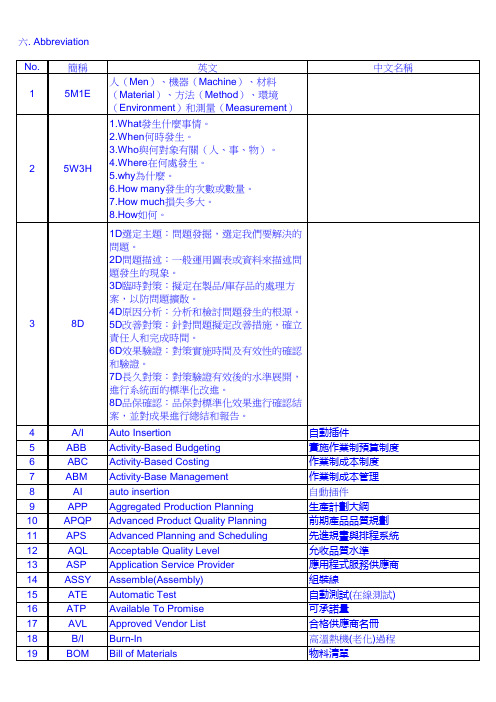
液晶顯示器 逐批訂購法 後進先出 長期供貨合約 最小總成本法 最小單位成本 主要 主要缺點 目標管理 材料不良報告 機械工程 製造執行系統 製造部(業) 次要 次要缺點 資訊中心 製造通知 作業指導書 量產 主要生產計劃 材料審查委員會 製造資源計劃 “材料安全數據表”,是一份危险物质的 详细的安全数据说明书,主要内容包 括危险物质的理化参数,危险特性, 毒性参数,接触限制,健康和环境危 害,安全运输、贮存和使用注意事 项,泄漏应急处置,急救措施以及有 关的法律法规等方面的信息。其主要 作用是使用户明了危险物质的有关危 害,在运输、储存、使用、处置的过 程中能主动进行防护,从而减少职业 危害、预防危害事故发生并减少对环 境的负面影响。 平均失效時間 生產驗證測試 更改預估量的通知 作業指導書 過電流保護 原始設計生產 原始配備生產 線上分析處理
物料清單 企業流程再造 平衡績分卡 計劃生產 訂單生產 製程準確度 電腦輔助設計/製造 儀器校驗 (儀校) 改善對策報告 客戶抱怨/要求 索取費用 無法複製,異常現象消失 製程精密度 每一百萬個使用者會有幾次抱怨 嚴重缺點(CR>MA>MI) 客戶關係管理 產能需求規劃 客戶服務 限制驅導式排程法 文件控制中心 (會計) 帳目通知
六. Abbreviation No. 1 簡稱 5M1E 英文 人(Men)、機器(Machine)、材料 (Material)、方法(Method)、環境 (Environment)和測量(Measurement) 1.What發生什麼事情。 2.When何時發生。 3.Who與何對象有關(人、事、物)。 4.Where在何處發生。 5.why為什麼。 6.How many發生的次數或數量。 7.How much損失多大。 8.How如何。 1D選定主題:問題發掘,選定我們要解決的 問題。 2D問題描述:一般運用圖表或資料來描述問 題發生的現象。 3D臨時對策:擬定在製品/庫存品的處理方 案,以防問題擴散。 4D原因分析:分析和檢討問題發生的根源。 5D改善對策:針對問題擬定改善措施,確立 責任人和完成時間。 6D效果驗證:對策實施時間及有效性的確認 和驗證。 7D長久對策:對策驗證有效後的水準展開, 進行系統面的標準化改進。 8D品保確認:品保對標準化效果進行確認結 案,並對成果進行總結和報告。 Auto Insertion Activity-Based Budgeting Activity-Based Costing Activity-Base Management auto insertion Aggregated Production Planning Advanced Product Quality Planning Advanced Planning and Scheduling Acceptable Quality Level Application Service Provider Assemble(Assembly) Automatic Test Available To Promise Approved Vendor List Burn-In 自動插件 實施作業制預算制度 作業制成本制度 作業制成本管理 自動插件 生產計劃大綱 前期產品品質規劃 先進規畫與排程系統 允收品質水準 應用程式服務供應商 組裝線 自動測試(在線測試) 可承諾量 合格供應商名冊 高溫熱機(老化)過程 中文名稱
特种文献(标准和专利)

45
ISO扩展检索
46
扩展检索说明
Find keyword or phrase(关键词或词组) 可输入单词或词组进行检索,词组必须臵于双 引号(“”)中; 支持布尔逻辑运算(and/not/or);如果在该 字段中一次输入2个或以上检索词,系统默认 各词之间以“OR”算符相连; 支持截词检索,采用“*”为截词符; 不区分大小写; 关键词检索可以选择是在标题、文摘和标准全 文里。
发表的方式不同:
分类体系不同:
性质不同:
8
5 标准文献表现形式
命名方式: 标准 规范 规程 Standard(标准)、 Specification(规格、规范)、 Rules、Instruction(规则) Process (工艺)
9
6 标准文献概况
目前,世界已有的技术标准达75万件以上,与标准有关的
2
技术标准战略的意义
知识产权比知识本身重要,技术标准比技术
本身重要。 尽快研究建立既符合世贸规则,又能保护本 国利益的国家技术标准体系
3
2 标准的类型
按标准的适用范围划分:
国际标准
区域标准
国家标准 专业标准 企业标准
4
2 标准的类型
按标准的性质划分:
基本标准
产品标准
方法标准 组织管理标准
5
2 标准的类型
按成熟度划分为
强制标准 推荐标准
6
3 标准文献及其作用
标准文献包括一切与标准化工作有关
的文献 标准文献是标准化工作的成果,也是 进一步推动科研、生产标准化进程的 动力,标准文献有助于了解各国的经 济政策、生产水平、资源情况和标准 化水平。