科隆IFM4080流量计说明书
科隆流量计modbus通讯手册
科隆流量计modbus通讯手册IFC 300Supplementary HandbookSignal converter withModbus interface for OPTIFLUX electromagnetic flowmeters Modbus ER 3.2.xx ( SW.REV.3.2.x )Modbus version 1.1.xSubject to change without notice. KROHNE 09 / 2008IFC 300 ModbusContent1 Importantinformation 3 2 Technicaldata 33 Connection of instruments in bus system 44 Electricalconnection 4 5 Modbus protocol 5 – 16 5.1 General 5 5.2 RTU Frame format 5 5.3 Overview of supported function 6 5.4 Device identification on the Modbus interface 6 5.5 Coilregisters 7 5.5.1 GDC Controls 7 5.5.2 Start calibration function 7 5.5.3 Counter controls 7 5.6 Inputregisters 8 5.7 Holding registers 9 –12 5.7.1 Counter parameters 9 – 10 5.7.2 Process input filter parameters 11 – 12 5.7.3 Modbus parameters 12 5.8 Calibration procedures 13 – 15 5.8.1 Zero flow calibration 13 5.8.2 Coil temperature calibration 14 5.8.3 Conductivity calibration 155.9 Diagnostics 166 Form (for copying) to accompany a returned instrument 19 1 ImportantinformationThe flow converter with the RS 485 interface card fitted, is able to communicate with an external device (PC or other suitable computer system) using the Modbus protocol. This option allows data exchange between PC or computer and single or multiple devices.The bus configuration consists of one external device as a master and one or more converters as slaves. For bus operation the device address (menu C5.8.1), baud rate (menu C5.8.2) and settings (menu C5.8.3, C5.8.4 & C5.8.5) must be set in the converter. All devices connected to the bus, must have different unique addresses but the same baud rate and settings.2 TechnicaldataInterface RS 485, galvanically isolatedBaud rate 1200, 2400, 4800, 9600, 19200, 38400, 57600 or115200 baudProtocol ModbusRTU(available as a separate document on request) Maximum participants on Bus 32 per line, master included(may be extended by repeaters)Coding NRZ bit codingAddress range Modbus: 1 (247)Transmission procedure Half duplex, asynchronousBus access Master / slaveCable Screened twisted pair cableDistances Maximum 1.2 km without repeater.(dependant on baud rate and cable specifications)Technical data of the Modbus interface (according to EIA standards)Kind of signal transmission DifferentialMaximum number of transmitter/receivers 32Maximum voltage on driver output -7 … +12 VMinimum voltage on driver output, max. load U diff > 1,5 V Maximum input current (off state) -20 … +20 μAReceiver input voltage -7 V … +12 VSensitivity of the receiver -200 … +200 mVReceiver input resistance > 12 kOhmShort circuit current of transmission < 250 mA3 Connection of instruments in bus systemsNetwork Biasing ResistorsFor proper operation of Modbus in half duplex mode in single or multi-drop communication, it is recommended that a termination resistor (typically 120 ohm) isapplied to both ends of the data line. The simplest form of termination is line-to-lineresistor across the differential input.In RTU mode the Modus protocol requires quiet periods on the communications bus for synchronisation. It is therefore important that the Modbus is not allowed to ‘float’, i.e. unreferenced to 0V, as this could lead to spurious signals due to noise pick-up. It is therefore necessary to employ biasing resistors at one point on the bus network,normally the “end”.The Modbus converter has two conditions. Default is without termination. To get theactive termination the settings of jumper X5 and X6 on Modbus board must be changed then, see below.4 ElectricalconnectionTerminals A and B of the converter are dependant on the options selected at order.Refer to the Standard Handbook of the converter for connection details.Modbus connectionsTerminals DescriptionD- Signal A (D 0)D Signal B (D 1)C- Common 0 VC Not connectedJumper settings on the Modbus printed circuit boardJumperpositionDescriptionX5 X61 -2 1 – 2with termination2 -3 2 - 3without termination 5 Modbusprotocol5.1 GeneralUsing RTU (Remote Terminal Unit) format, data is transmitted as 8 bit binary characters. There are no special characters to determine the start and end of a message frame, synchronization is achieved by a minimum silent period of at least 3.5 character times before the start of each frame transmission and a maximum silent period of 1.5 character times between characters in the same frame.5.2 RTU Frame formatThe format of the Query and Response frames vary slightly depending upon the command function. The basic form is outlined below.SilentPeriodSlaveAddressFunctionCodeRegister Start Address orByte Count when requiredNo.of.Points orData bytes when requiredCRC3.5 T 8 bits 8 bits8 bit byte count16 bit addressn × 8 bits 16 bits Silent periodAll transmissions must be preceded by a minimum silent period of 3.5×T, where T is the transmission time of a single character. This can be calculated from the baud rate e.g. at 19.2 kb no parity with 1 stop bit (10 bits), T = 520 μs.Slave addressThis is a single byte slave address which is transmitted first and must be in the range of 1-247. Address 0 is reserved for a broadcast address which all slaves should recognize, and therefore requires no response.Function codeThis is an eight bit code in the range of 1 … 255 although only 126 functions exist as the codes 129-255 represent an error condition. An error condition occurswhen the addressed slave does not accept the command, in which case it responds with the function code + 128, i.e. with its MSB set to 1.Byte countIn general this is only present in frames that are transferring data, and has a value equal to the number of bytes contained in the data field.The data field is limited to a maximum of 250 bytes.Register start addressFor a query command that requires data to be returned, this field will contain the 16 bit start address of the register (or data)to be returned. Note that the converter uses protocol addresses. Therefore the register address listed is the actual number required in the Modbus command. E.g: To access input register 30006, the register start address is 30006dec = 7536hex Number of pointsFor a query command that requires data to be returned, this field will contain the number of registers to be returned regardless of their bit size.Data bytesContains the data requested. The converter can use big endian format (MSB first) or little endian format (LSB first).CRCThis field contains a 16 bit CRC which is calculated on all the data bits of the message bytes.5.3 Overview of supported functionsThe following table shows MODBUS functions supported by RS485 interfaceFunction code hex dec Name Accessto01 01 Read Single Coil Status of calibration functions, Counter status (Start/Stop)03 03 Read Holding Register Cyclic Register04 04 Read Input Register Acyclic Register05 05 Write Single CoilCold Start, Warm Start, Error Reset, Start calibration function, Start / Stop Counter08 08 Diagnostics10 16 Writ Multiple Register Acyclic Register2B 43 Encapsulated InterfaceTransportTransparent Channel, ReadDevice Identification5.4 DeviceIdentificationThe device identification is according to the category regular according to the MODBUS Application Protocol Specification V1.1a. Function code 43 / 14 (0x2B / 0x0E).Device identification on the Modbus interfaceModbusObject IdObject name / Description Type Content converter0x00 VendorName 16 ByteASCII StringKROHNE0x01ProductCode10 ByteASCII StringCG numberproduction0x02MajorMinorRevision7 ByteASCII StringV1.1.000x03Vendor URL32 ByteASCII String0x04ProductName16 ByteASCII StringConverter0x05ModelName16 ByteASCII StringModbus0x06UserApplicationName16 ByteASCII Stringuser tag, displayed onthe header of thelocal screen5.5 CoilregistersThese function codes are used for access: 0x01 = read input coil0x05 = write single coilAbreviations in the following tablesGDC General Device Conceptcnt counter5.5.1 GDCControlsCoil address Function1000 write 1 generates a GDC cold start, write of 0 is ignored 1001 write 1 generates a GDC warm start, write 0 is ignored 1002 write 1 generates a GDC error reset, write 0 is ignored5.5.2 Start calibration functionsModbusprotocoladdressDescription SettingsConverterFct. No.2000 Zerocalibration C1.1.12001 Coil temperature calibration C1.1.8 2002 Electrode factor calibrationwrite 1 = start function0 = -read 0 = - C1.1.115.5.3 CountercontrolsModbusprotocoladdressDescription SettingsConverterFct. No.3000 Start / Stop Counter 1C3.1.8 /C3.1.93001 Start / Stop Counter 2C3.2.8 /C3.2.93002 Start / Stop Counter 3write:read:1 = start counter0 =stop counter1 = cnt is running0 = cnt is stopped C3.3.8 /C3.3.93003 ResetCounter1 C3.1.63004 ResetCounter2 C3.2.63005 ResetCounter3write:read:1 = reset counter0 = -0 = - C3.3.65.6 InputregistersMeasurement and status values are read only and can be accessed asModbus "Input Registers".Cyclic GDC objects are mapped to Modbus Registers.Also the result of a calibration procedure is accessed by an input register at Modbus Protocol Address 20000. The type are one or more float values.Function code is 04 (0x04).Modbus protocol address Description andSettingsTypeNumberofregisters30000 Flow speed [m/s] float 2 30002 Volume flow [m3/s] float 2 30004 Mass flow [kg/s] float 2 30006 Coil temperature [K] float 230008 Conductivity [S/m]This value may not be measured.Depending on register 31200.0 = off (not measured)1 = conductivity [S/m]2 = conductivity + empty pipe (S) [S/m]2 = conductivity + empty pipe (F) [S/m]float 230010 Diagnosis valueThis value may not be measured.Depending on register 31216.25 = off (not measured)31 = electrode noise [m/s]28 = flow profile [no unit]21 = linearity [no unit]8 = terminal 2 DC [Volt]9 = terminal 3 DC [Volt]float 230012 Display channel 1Represents the value on the first line of the firstmeasurement screen in SI unitsfloat 230014 Display channel 2Represents the value on the first line of the secondmeasurement screen in SI unitsfloat 230016 Operating time [s] float 2 30018 not used, returns zero float 230020 Counter 1 [m3] or [kg] doublefloat430024 Counter 2 [m3] or [kg] doublefloat430028 Counter 3 [m3] or [kg](This counter is only available for converter with IO 2)doublefloat430032 Long status sensor byte [4] 2 30034 Long status device byte [4] 2 5.7 HoldingregistersSome parameters of the device can be accessed as Modbus holding registers. These registers are mapped to acyclic GDC objects.Function code 03 (0x03) for read operations andfunction code 16 (0x10) for write operations.The holding registers are grouped into different sections:5.7.1 CounterparametersModbusprotocoladdressDescription andSettingsConverterFct. No.Type Number of registers 40000 Counter 1 function1 = sum counter2 = + counter3 = - counter0 = offC3.1.1 byte 1 40001 Measurement Cnt 121 = volume flow22 = mass flowC3.1.2 byte 1 40002Counter 2 function,1 = sum counter2 = + counter3 = - counter0 = offC3.2.1 byte 1 40003 Measurement Cnt 221 = volume flow22 = mass flowC3.2.2 byte 1 40004Counter3 function,1 = sum counter2 = + counter3 = - counter0 = offC3.3.1 byte 1 40005 Measurement Cnt 321 = volume flow22 = mass flowC3.3.2 byte 1Modbus protocol address Description andSettingsConverterFct. No.Type Number of registers41000 Low flow cutoff valueCnt 1 [m3] or [kg]C3.1.3 float 241002 Time constant Cnt 1 [s] C3.1.4 float 2 41004 Set Cnt 1 [m3] or [kg] C3.1.7 float 241006 Low flow cutoff valueCnt 2 [m3] or [kg]C3.2.3 float 241008 Time constant Cnt 2 [s] C3.2.4 float 2 41010 Set Cnt 2 [m3] or [kg] C3.2.7 float 241012 Low flow cutoff valueCnt 3 [m3] or [kg]C3.3.3 float 241014 Time constant Cnt 3 [s] C3.3.4 float 2 41016 Set Cnt 3 [m3] or [kg] C3.3.7 float 241018 Preset counter 1[m3] or [kg]C3.1.5 float 241020 Preset counter 2[m3] or [kg]C3.2.5 float 241022 Preset counter 3[m3] or [kg]C3.3.5 float 2Note: Counter 3 parameters are only available for converter with IO 2 ! 5.7.2 Process input filter parametersModbusprotocoladdressDescription andSettingsConverterFct. No.TypeNumber ofregisters 42000Flow direction0 = normal direction1 = reverse directionC1.2.2 byte 1 42001Pulse filter0 = off / 1 = onC1.2.4 byte 1 42002Noise filter0 = off / 1 = onC1.2.7 byte 1 42003Empty pipe0 = off1 = conductivity2 = conductivity +empty pipe (S)3 = conductivity +empty pipe (F)C1.3.1 byte 1 42004 Full pipe0 = off / 1 = onC1.3.4 byte 1 42005 Linearity0 = off / 1 = onC1.3.6 byte 1 42006 Gain0 = off / 1 = onC1.3.8 byte 1 42007 Coil current0 = off / 1 = onC1.3.9 byte 1 42008 Flow profile0 = off / 1 = onC1.3.10 byte 1 42009 Electrode noise0 = off / 1 = onC1.3.13 byte 1 42010 Setting of field0 = off / 1 = onC1.3.16 byte 1 42011 Diagnosis value25 = off31 = electrode noise 28 = flow profile21 = linearity8 = terminal 2 DC9 = terminal 3 DCC1.3.17 byte 1Modbus protocol address Description andSettingsConverterFct. No.TypeNumber ofregisters43000 Limitation low [m/s] C1.2.1 float 2 43002 Limitationhigh[m/s] C1.2.1 float 2 43004 Time constant [s] C1.2.3 float 2 43006 Pulse width [s] C1.2.5 float 2 43008 Pulse limitation [m/s] C1.2.6 float 2 43010 Noise level [m/s] C1.2.8 float 2 43012 Noise suppression C1.2.9 float 2 43014 Low flow cuttoff value [m/s] C1.2.10 float 2 43016 Limit empty pipe [S/m] C1.3.3 float 2 43018 Limit full pipe [S/m] C1.3.5 float 2 43020 Limit flow profil C1.3.11 float 2 43022 Limit electrode noise [m/s] C1.3.14 float 2 43024 Zero point [m/s] C1.1.1 float 2 43026 Coil resistance Rsp, 20 [Ohm] C1.1.7 float 2 43028 Coil temperature calpoint [K] C1.1.8 float 2 43030 Coil resistance calpoint [Ohm] C1.1.8 float 2 43032 Electrode factor EF [m] C1.1.11 float 2 43034 Conductivity calpoint [S/m] C1.1.11 float 2 43036 Conductivity calpoint [S/m] C1.1.11 float 2 5.7.3 ModbusparametersModbusprotocoladdressDescription andSettingsConverterFct. No.TypeNumber ofregisters 50000Baud rate1200 / 2400 / 3600 / 4800 / 9600 /19200 / (default) / 38400 / 57600 /115200C5.8.2 ulong 2 50002 Slave address C5.8.1 byte 1 50003 Parity0 = even parity (default)1 = odd parity3 = no parityC5.8.3 byte 1 50004Data format1 = big endian2 = little endianC5.8.4 byte 1 50005Stop bits1 = 1 stop bit (parity is used)2 = 2 stop bits (parity is not used)C5.3.6 byte 25.8 Calibrationprocedures5.8.1 Zero flow calibration5.8.2 Coil temperature calibration5.8.3 Conductivity calibration5.9 DiagnosticsThe Modbus interface supports the diagnostic function defined by the Modbusapplication protocol specification.Function code is 08 (0x08).Sub - function codehex dec Name00 00 Return query data 01 01 Restart communication option 04 04 Force listen only mode 0A 10 Clear counters 0B 11 Return bus message count 0C 12 Return bus communication error count 0D 13 Return bus exception count 0E 14 Return slave message count 0F 15 Return slave no response count 10 16 Return slave NAK count (counter not used) 11 17 Return slave busy count (counter not used) 12 18 Return bus character overrun count Notice6 Form (for copying) to accompany a returned instrument。
科隆电磁流量计转换器快速操作手册
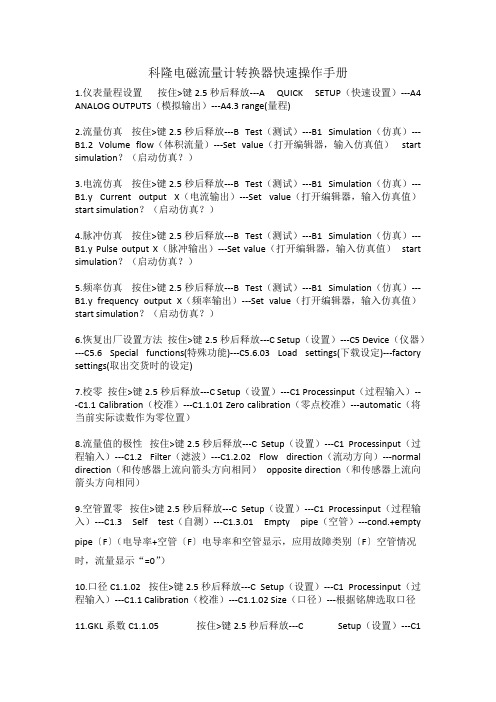
科隆电磁流量计转换器快速操作手册1.仪表量程设置按住>键2.5秒后释放---A QUICK SETUP(快速设置)---A4 ANALOG OUTPUTS(模拟输出)---A4.3 range(量程)2.流量仿真按住>键2.5秒后释放---B Test(测试)---B1 Simulation(仿真)---B1.2 Volume flow(体积流量)---Set value(打开编辑器,输入仿真值)start simulation?(启动仿真?)3.电流仿真按住>键2.5秒后释放---B Test(测试)---B1 Simulation(仿真)---B1.y Current output X(电流输出)---Set value(打开编辑器,输入仿真值)start simulation?(启动仿真?)4.脉冲仿真按住>键2.5秒后释放---B Test(测试)---B1 Simulation(仿真)---B1.y Pulse output X(脉冲输出)---Set value(打开编辑器,输入仿真值)start simulation?(启动仿真?)5.频率仿真按住>键2.5秒后释放---B Test(测试)---B1 Simulation(仿真)---B1.y frequency output X(频率输出)---Set value(打开编辑器,输入仿真值)start simulation?(启动仿真?)6.恢复出厂设置方法按住>键2.5秒后释放---C Setup(设置)---C5 Device(仪器)---C5.6 Special functions(特殊功能)---C5.6.03 Load settings(下载设定)---factory settings(取出交货时的设定)7.校零按住>键2.5秒后释放---C Setup(设置)---C1 Processinput(过程输入)---C1.1 Calibration(校准)---C1.1.01 Zero calibration(零点校准)---automatic(将当前实际读数作为零位置)8.流量值的极性按住>键2.5秒后释放---C Setup(设置)---C1 Processinput(过程输入)---C1.2 Filter(滤波)---C1.2.02 Flow direction(流动方向)---normal direction(和传感器上流向箭头方向相同)opposite direction(和传感器上流向箭头方向相同)9.空管置零按住>键2.5秒后释放---C Setup(设置)---C1 Processinput(过程输入)---C1.3 Self test(自测)---C1.3.01 Empty pipe(空管)---cond.+empty pipe〔F〕(电导率+空管〔F〕电导率和空管显示,应用故障类别〔F〕空管情况时,流量显示“=0”)10.口径C1.1.02 按住>键2.5秒后释放---C Setup(设置)---C1 Processinput(过程输入)---C1.1 Calibration(校准)---C1.1.02 Size(口径)---根据铭牌选取口径11.GKL系数C1.1.05 按住>键2.5秒后释放---C Setup(设置)---C1Processinput(过程输入)---C1.1 Calibration(校准)---C1.1.05 GKL---根据铭牌设定数值12.磁场频率(Field frequency)C1.1.13 按住>键2.5秒后释放---C Setup(设置)---C1 Processinput(过程输入)---C1.1 Calibration(校准)---C1.1.1 Zero calibration(零点校准)---C1.1.13 Field frequency(磁场频率)---13.电流输出开启(Current output)C2.1.1 按住>键2.5秒后释放---C Setup(设置)---C2 I/O(输入/输出)---C2.1 Hardware(硬件)---C2.1.1 Terminals A(端子A)---Current output(电流输出开启)/Off(电流输出关闭,该端子无任何功能)14.频率输出开启(Frequency output)C2.1.4 按住>键2.5秒后释放---C Setup(设置)---C2 I/O(输入/输出)---C2.1 Hardware(硬件)---C2.1.1 Terminals A(端子A)---C2.1.4 Terminals D(端子D)---Frequency output (频率输出)/Pulse output (脉冲输出)/Status output (状态输出开启)/Limit switch(限位开关开启)/Off(关闭,该端子无任何功能)15.量程(Range)C2.2.6 按住>键2.5秒后释放---C Setup(设置)---C2 I/O(输入/输出)---C2.2 Current output A(c2.2=A C2.3=B C2.4=C)---C2.2.1 Range 0%-100%(电流输出量程,例如4-20MA)---C2.2.6 Range(量程)---测量范围为0%-100%16.极性(Polarity)C2.2.7 按住>键2.5秒后释放---C Setup(设置)---C2 I/O(输入/输出)---C2.2 Current output A(c2.2=A C2.3=B C2.4=C)---C2.2.1 Range 0%-100%(电流输出量程,例如4-20MA)---C2.2.7 Polarity(极性)---Both polarities (使用正、负数值)/Positive polarity (用正值,负值用力0%代替)/Negative polarity (用负值,正值用0%代替)/Absolute value(用测量值的绝对值作为电流输出)17.指示流量传感器的衬里材料(Liner)C1.4.1 按住>键2.5秒后释放---C Setup(设置)---C1 Process input(过程输入)---C1.1 Calibraton(校准)---C1.4 Information(所有传感器的电子信息)---C1.4.1 Liner (指示流量传感器的衬里材料)---PTFE(聚四氟已稀)、PFA(衬里)、NEOPRENE(氯丁橡胶)、POLYURETHANE(聚氨酯橡胶)18.指示电极材料(Eletr.material)C1.4.1 按住>键2.5秒后释放---C Setup(设置)---C1 Process input(过程输入)---C1.1 Calibraton(校准)---C1.4 Information(所有传感器的电子信息)---C1.4.2 Electr.material (指示传感器电极材料)---MO2TI、HC、HB、TI、TA、PT19.在测量页中打开累加器(1ST meas.page 1)C5.3 按住>键2.5秒后释放---C Setup(设置)---C1 Process input(过程输入)---C5 Device(设备)---C5.3 1st meas.page 1(第一测量显示屏)---C5.3.8 measurement 2nd line (第二测量行)---counter1(在Profibus 中为FB2累加器)20.在测量页2中打开电导率测量(2ST meas.page 2)C5.3 按住>键2.5秒后释放---C Setup(设置)---C1 Process input(过程输入)---C5 Device(设备)---C5.4 2nd meas.page 2(第一测量显示屏)---C5.4.8 measurement 1st line (第一测量行)---conductivity(电导率)。
科隆电磁流量计转换器快速操作手册
科隆电磁流量计转换器快速操作手册1.仪表量程设置按住>键2.5秒后释放---A QUICK SETUP(快速设置)---A4 ANALOG OUTPUTS(模拟输出)---A4.3 range(量程)2.流量仿真按住>键2.5秒后释放---B Test(测试)---B1 Simulation(仿真)---B1.2 Volume flow(体积流量)---Set value(打开编辑器,输入仿真值)start simulation?(启动仿真?)3.电流仿真按住>键2.5秒后释放---B Test(测试)---B1 Simulation(仿真)---B1.y Current output X(电流输出)---Set value(打开编辑器,输入仿真值)start simulation?(启动仿真?)4.脉冲仿真按住>键2.5秒后释放---B Test(测试)---B1 Simulation(仿真)---B1.y Pulse output X(脉冲输出)---Set value(打开编辑器,输入仿真值)start simulation?(启动仿真?)5.频率仿真按住>键2.5秒后释放---B Test(测试)---B1 Simulation(仿真)---B1.y frequency output X(频率输出)---Set value(打开编辑器,输入仿真值)start simulation?(启动仿真?)6.恢复出厂设置方法按住>键2.5秒后释放---C Setup(设置)---C5 Device(仪器)---C5.6 Special functions(特殊功能)---C5.6.03 Load settings(下载设定)---factory settings(取出交货时的设定)7.校零按住>键2.5秒后释放---C Setup(设置)---C1 Processinput(过程输入)---C1.1 Calibration(校准)---C1.1.01 Zero calibration(零点校准)---automatic(将当前实际读数作为零位置)8.流量值的极性按住>键2.5秒后释放---C Setup(设置)---C1 Processinput(过程输入)---C1.2 Filter(滤波)---C1.2.02 Flow direction(流动方向)---normal direction(和传感器上流向箭头方向相同)opposite direction(和传感器上流向箭头方向相同)9.空管置零按住>键2.5秒后释放---C Setup(设置)---C1 Processinput(过程输入)---C1.3 Self test(自测)---C1.3.01 Empty pipe(空管)---cond.+empty pipe〔F〕(电导率+空管〔F〕电导率和空管显示,应用故障类别〔F〕空管情况时,流量显示“=0”)10.口径C1.1.02 按住>键2.5秒后释放---C Setup(设置)---C1 Processinput(过程输入)---C1.1 Calibration(校准)---C1.1.02 Size(口径)---根据铭牌选取口径11.GKL系数C1.1.05 按住>键2.5秒后释放---C Setup(设置)---C1Processinput(过程输入)---C1.1 Calibration(校准)---C1.1.05 GKL---根据铭牌设定数值12.磁场频率(Field frequency)C1.1.13 按住>键2.5秒后释放---C Setup(设置)---C1 Processinput(过程输入)---C1.1 Calibration(校准)---C1.1.1 Zero calibration(零点校准)---C1.1.13 Field frequency(磁场频率)---13.电流输出开启(Current output)C2.1.1 按住>键2.5秒后释放---C Setup(设置)---C2 I/O(输入/输出)---C2.1 Hardware(硬件)---C2.1.1 Terminals A(端子A)---Current output(电流输出开启)/Off(电流输出关闭,该端子无任何功能)14.频率输出开启(Frequency output)C2.1.4 按住>键2.5秒后释放---C Setup(设置)---C2 I/O(输入/输出)---C2.1 Hardware(硬件)---C2.1.1 Terminals A(端子A)---C2.1.4 Terminals D(端子D)---Frequency output (频率输出)/Pulse output (脉冲输出)/Status output (状态输出开启)/Limit switch(限位开关开启)/Off(关闭,该端子无任何功能)15.量程(Range)C2.2.6 按住>键2.5秒后释放---C Setup(设置)---C2 I/O(输入/输出)---C2.2 Current output A(c2.2=A C2.3=B C2.4=C)---C2.2.1 Range 0%-100%(电流输出量程,例如4-20MA)---C2.2.6 Range(量程)---测量范围为0%-100%16.极性(Polarity)C2.2.7 按住>键2.5秒后释放---C Setup(设置)---C2 I/O(输入/输出)---C2.2 Current output A(c2.2=A C2.3=B C2.4=C)---C2.2.1 Range 0%-100%(电流输出量程,例如4-20MA)---C2.2.7 Polarity(极性)---Both polarities (使用正、负数值)/Positive polarity (用正值,负值用力0%代替)/Negative polarity (用负值,正值用0%代替)/Absolute value(用测量值的绝对值作为电流输出)17.指示流量传感器的衬里材料(Liner)C1.4.1 按住>键2.5秒后释放---C Setup(设置)---C1 Process input(过程输入)---C1.1 Calibraton(校准)---C1.4 Information(所有传感器的电子信息)---C1.4.1 Liner (指示流量传感器的衬里材料)---PTFE(聚四氟已稀)、PFA(衬里)、NEOPRENE(氯丁橡胶)、POLYURETHANE(聚氨酯橡胶)18.指示电极材料(Eletr.material)C1.4.1 按住>键2.5秒后释放---C Setup(设置)---C1 Process input(过程输入)---C1.1 Calibraton(校准)---C1.4 Information(所有传感器的电子信息)---C1.4.2 Electr.material (指示传感器电极材料)---MO2TI、HC、HB、TI、TA、PT19.在测量页中打开累加器(1ST meas.page 1)C5.3 按住>键2.5秒后释放---C Setup(设置)---C1 Process input(过程输入)---C5 Device(设备)---C5.3 1st meas.page 1(第一测量显示屏)---C5.3.8 measurement 2nd line (第二测量行)---counter1(在Profibus 中为FB2累加器)20.在测量页2中打开电导率测量(2ST meas.page 2)C5.3 按住>键2.5秒后释放---C Setup(设置)---C1 Process input(过程输入)---C5 Device(设备)---C5.4 2nd meas.page 2(第一测量显示屏)---C5.4.8 measurement 1st line (第一测量行)---conductivity(电导率)。
开封科隆智能电磁流量计选用说明书概要

流等信号,用于流量的控制和调节。
E=KBdv
式中:E---------------为电极间的信号电压(v
B-----------------磁通密度(T
所没有的。测量管内无活动及阻流部件,因此几乎没有压力损失,并且有分高的可靠性。
2.应用领域
由于电磁流量计有其独特的优点,因此被广泛用于化工化纤、食品、造纸、制糖、矿冶、给排水、环保、
水利水工、钢铁、石油、制药等工业领域中,用来测量各种酸、碱、盐溶液、泥浆、矿浆、纸浆、煤水浆、
玉米浆、纤维浆、粮浆、石灰乳、污水、冷却原水、给排水、盐水、双氧水、啤酒、麦汁、各种饮料、黑液、绿液等导电液体介质的体积流量。
智
书
开封科隆流量仪表有限公司
一、智能电磁流量计
智能电磁流量计是我公司采用国内外最先进技术研制开发的全智能型电磁流量计,全中文电
磁转换器内核采用高速中央处理器。计算速度非常快、精度高、测量性能可靠。转换器电路设计采用国际先进技术,输入阻抗高达1015欧姆,共模抑制比优于100db,对于外来干扰以及60Hz/50Hz干扰抑制能力优于90db,可以测量更低的电导率的流体介质流量。其传感器采用非均匀磁场技术及特殊的磁路结构,磁场稳定可靠,而且大的缩小了体积,减轻了重复,使流量计小型流量化的特点。使客户买的放心,用的省心,服
▲具有自检与自论功能
二、概述
1.工作原理
电磁流量计测量原理是基于法拉第电磁感应定律。流量计
的测量管是一内衬绝缘材料的非导磁合金短管。两只电极沿
科隆电磁流量计说明书IFC
8
IFC 300
04 / 2006
1.3 分体(墙挂)型传感器的电气连接
1.3.1 A 型、B 型信号电缆和励磁电缆 C 的通用信息
使用我们提供的 A 型双层屏蔽或 B 型三层屏蔽信号电缆可以保证仪表的正常使用
如果您要使用其它的信号电缆,请注意下列电气参数!
电气安全符合EN 60811
测试电压
(低电压规程)
电源连接 (适用于所有型式/外壳型式)
电源消耗 • 对于 AC = 22 VA • 对于 DC = 12 W
AC: 100 - 230 V (-15% / +10%) PE
N
L
DC: 12 - 24 V (-25% / +30%)
FE
L-
L+
附加的带铰链的盖子保护接线盒内的接线端子被意外触及
警告: 信号转换器必须有良好的接地,以避免对人员产生电击危险。所有的说明、操作数 据和连接图都不适用于危险场合使用的仪表,务必阅读专门的“Ex” 操作手册!
内层1通过排扰线连接到接线端外层60通过编织网和u夹子连接绝缘材料符合en5062521iec603221或等同的国家标准的要求信号电缆采用低卤不含增塑剂的绝缘材料低温时应保持柔软a型信号电缆ds300型双层屏蔽1排扰线内屏蔽10mm?铜线awg17不绝缘裸铜线10内屏蔽见排扰线12带绝缘层电线05mm?awg20标记23带绝缘层电线05mm?awg20标记36排扰线外屏蔽05mm?铜线awg20不绝缘裸铜线60外屏蔽见排扰线6外护套直径大约8mm03标记ds300b型信号电缆bts300型三层屏蔽自举线1排扰线内屏蔽10mm?铜线awg17不绝缘裸铜线10内屏蔽见排扰线12带绝缘层电线05mm?awg20标记220导线2单独的排扰线3带绝缘层电线05mm?awg20标记330导线3单独的排扰线6排扰线外屏蔽05mm?铜线awg20不绝缘裸铜线60外屏蔽见排扰线6外护套直径大约12mm05标记bts300使用自举方式时单独的屏蔽层20和30总是由转换器控制使得和出现在信号线2和3上的电压完全相同这样在芯线2和3和独立的屏蔽20和30之间没有电位差就没有电流流过220或330之间的电容显然线电容为零这样就允许在低电导率流体时使用更长的电缆励磁电缆c截面积取决于需要的电缆长度见表133
ifm电子流量计器产品说明书
Resolution
Set point SP
Reset point rP
Measuring dynamics
Frequency end point, FEP
Frequency at the end point FRP
[Hz]
In steps of
0.2...10 gpm 0...12 gpm
0.1 gpm 0.1...10 gpm 0...9.9 gpm
stainless steel (1.4401 / 316); stainless steel (1.4404 / 316L); brass (2.0371); brass chemically nickel-plated; PPS; O-ring: FKM
Process connection
threaded connection 3/4 NPT
hysteresis / window; normally open / normally closed; switching logic; current output; medium selection; damping for the switching output / analogue output; display can be rotated and switched off; standard unit of measurement; process value colour
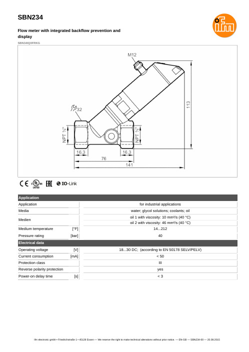
SBN234
Flow meter with integrated backflow prevention and display
SBN34IQ0FRKG
Connection
OUT1: OUT2: -
BK = BN = BU = WH =
科隆电磁流量计技术参数说明书

科隆电磁流量计技术参数说明书科隆电磁流量计,那可是个厉害的家伙呀!它就像一位精准的计量大师,默默地在各种工业场景中发挥着重要作用。
咱先来说说它的测量范围。
那可真是相当宽泛啊,无论是小流量的涓涓细流,还是大流量的汹涌澎湃,它都能稳稳地给你测量出来。
这就好比一个武林高手,不管是对付小喽啰还是大魔头,都能轻松应对,厉害吧!精度呢,也是杠杠的!能精确到让人惊叹的程度,就像一个极其细心的工匠,一丝一毫的偏差都逃不过它的法眼。
这意味着啥?意味着你能得到超级可靠的数据呀,这数据可是工业生产中的宝贝呢!再看看它的重复性。
哇哦,那简直可以说是屡试不爽,每次测量的结果都那么相近,稳定得让人安心。
就好像你每天出门都能看到门口那棵熟悉的大树,稳稳地在那里,给你一种踏实的感觉。
还有它的压力损失。
嘿,特别小!就跟没有似的,完全不会对流体的流动造成什么大影响。
这就好比你在路上轻快地走着,几乎感觉不到什么阻力,一路畅通无阻啊。
科隆电磁流量计对流体的适应性也很强呢。
不管是清水、污水,还是各种奇奇怪怪的液体,它都能照单全收,准确测量。
这就像是一个全能型选手,什么项目都能玩得转。
再说说它的工作温度和压力范围。
那也是相当宽泛的呀,高温不怕,高压也不惧,简直就是个硬汉!在各种恶劣环境下都能顽强地工作着,这精神,不值得我们学习吗?而且哦,它的安装和维护也相对简单。
不需要你费多大的劲,就能轻松搞定。
就像给手机换个电池那么容易,你说方便不方便?总之,科隆电磁流量计就是这样一个厉害的角色,在工业领域里默默地奉献着自己的力量。
它的这些技术参数可都是它的拿手好戏呀,让它成为了众多工程师和企业的得力助手。
有了它,我们就能更准确地掌握流体的情况,让生产和工作更加高效、可靠。
你说它是不是很了不起呢?难道你不想拥有这样一个可靠的伙伴吗?。
流量计说明书
一、概述1、简介冲板式散状固体流量计(以下简称冲板流量计)由测量部分(一次表),显示输出部分(二次表)以及连接壳体组成。
它经常与螺旋给料机、叶轮给料机、斗式提升机、传送带等配合使用。
2、测量原则物料下落到检测板上产生水平分力,此水平分力作用于冲板流量计一次表内部的测力传感器使之产生电信号并传送给二次表,由二次表显示并输出与之对应的瞬时流量。
二、主要配置——冲板流量计一次表(含测量本体,传感器,检测板)一台——冲板流量计连接壳体——冲板流量计显示表一台三、技术规格一次表防尘:自身结构防尘耐电压:端子与箱体之间1分钟1000VAC。
绝缘:500VDC,100M 以上。
涂饰:银色。
材质:一次表主体用铝铸件。
传感器:测力传感器适用温度: -10℃—+50℃安全载荷: 150%接线说明: 红15VDC或12VDC+ 黑—;输出绿0~20mVDC+ 白—(颜色以实际发货说明为准)四、操作(一)、安装使用注意事项1、模拟输入与输出信号对电子噪声敏感,请将这些线远离交流电源,并尽量缩短屏蔽电缆的长度,如现场有干扰,请将屏蔽电缆的屏蔽线良好接地。
2、冲板流量计测量的数据受以下三个因素影响:冲击角、检测板水平安装角度和物料自由下落高度。
所以当技术人员协助安装调试后不要轻易改动以上因素。
(二)校准1、初次使用(1)整流壳体和流路对接之后,将冲板流量计安装在整流壳体的基座上,将密封橡胶的法兰和地脚螺栓紧固,进行简单的水平调节。
(2)打开整流壳体门,先将轴插入轴套内,将轴套内的紧固顶丝紧固。
(3)将冲击板通过瓦座穿在轴上,将冲击板调整到合适的角度后(对地角度:60-90度),将冲击板固定在轴上。
(4)将阻尼油注入阻尼器,使阻尼器中充满油且无气泡。
(5)传感器输出红、黑端电源10-15VDC ;绿、白端输入0~20mVDC 。
(6)接线图: (以实际发货为准)传感器供电传感器输出红黑-白-绿现场变送器(7)标定冲板流量计现场校正主要采用实物校正的形式。
- 1、下载文档前请自行甄别文档内容的完整性,平台不提供额外的编辑、内容补充、找答案等附加服务。
- 2、"仅部分预览"的文档,不可在线预览部分如存在完整性等问题,可反馈申请退款(可完整预览的文档不适用该条件!)。
- 3、如文档侵犯您的权益,请联系客服反馈,我们会尽快为您处理(人工客服工作时间:9:00-18:30)。
安装和使用说明书电磁流量计IFM 4080 K+F ()IFM 3080 K+F 3.1 - SGAIC - I - 6IFC 090 F 信号转换器IFM 4080 K01/02ElectromagneticFlowmetersIFS 4000 F 传感器中德合资 上海光华·爱而美特仪器有限公司计量器具许可证: 沪字00000443号上海光华·爱而美特仪器有限公司已通过 ISO 9002 国际国内双重认证IFM 4080电磁流量计的组合式Krohne 系统在特定的应用中,组合式Krohne 系统是合适的电磁流量计----从流量测量和经济观点来看都是合适的。
IFC 090 可与所有的Krohne 传感器相配IFS 5000 陶瓷测量管,无法兰的设计IFS 4000 具有PFA 或其他衬里,有法兰的设计M 900 作为特殊应用,例如卫生型,额定压力可高达PN1500(或 20000磅/平方英寸表压)和现场可更换电极型式的代码IFM... 电磁流量计IFS... (M900)传感器IFC... 信号转换器K 一体型F 分体型传感器的详细数据在有关的数据册中规定IFM 4080 K IFS 4000 FM 900IFM 3080 (M 900 + IFC 090 信号转换器)一体型分体型111222-31.1 简要说明1.2 IFC 090 信号转换器分类1.3 信号转换器供电形式1.4 外壳材料及防护等级1.5 参比条件下误差曲线1.6 信号转换器方框图简述2.1 安装与电气连接要求2.2 接线端子电气连接图2.3 输入输出连接方式2.4 输入输出说明与组合2.5 厂方设定2.6 仪表启动3.1 IFC 090 D 面板注释3.2 操作按键的功能3.3 KROHNE 公司操作规则3.4 缩写字母表示含义3.5 功能设定表3.6 在测量状态下出错信息3.7 积算器复位及出错信息的消除3.8 修改设定范例4.1 满量程范围4.2 时间常数4.3 小流量切除4.4 显示4.5 内部电子积算器4.6 电流输出 I 4.7 脉冲输出B 14.8 状态输出B 1和B 24.9 显示文本和语种4.10 进入编程的密码4.11 传感器参数设定4.12 用户自定义单位4.13 F/R 正/反向流量方式测量4.14 输出特性图4.15 控制输入B 1和B 24.16 应用4.17 二进制输入和输出的组成444-67-8991010-11121313-171717-1818191919-2020202121-222323242425262626-2727274.18 限位开关4.19 自动量程切换BA 5.1 用于危险场合5.2 手操机终端和包括CONFIG 组态软件的RS 232适配器5.3 测量管排空时信号的稳定输出5.4 脉冲流量情况下设定方法5.5 测量流率的快速响应5.6 不稳定显示和输出6.1 IFC 090K/D 信号转换器的零位检查,Fct3.036.2 测量范围Q 的测试,Fct2.016.3 硬件信息和出错情况检查,Fct2.026.4 用GS8A 模拟信号器测试IFC090转换器7.1 线路板图解7.2 信号转换器壳体盖开启要求与注意点7.3 电源保险丝的更换及保险丝的规格表7.4 改变交流 AC 型 1 型和 2 型工作电压方法7.5 显示线路板转向和更换7.6 IFC 090转换器电气单元的更换方法1. IFS 4000与IFC 090的组合及型号命名2. 传感器在管线上的安装2.1 安装要求2.2 IFS 4000的衬里2.3 IFS 4000的电极2.4 接地环2.5 接地2.5.1 在内表面没有涂层的金属管道上的接地安装2.5.2 在塑料管道或内表面涂有绝缘层的金属管道上的接地安装2.5.3 具有阴极保护管道的接地安装2.6 电缆的敷设2.7 允许负压的极限3. IFS 4000与转换器组合时的接线图3.1 IFM 4080F(IFS 4000+IFC 090)4. IFS 4000的外形、连接尺寸及重量4.1 IFS 4000的法兰标准4.2 IFS 4000的外形、连接尺寸及重量表5. M 900 电磁流量传感器尺寸、重量6 电磁流量传感器的工作原理27-282829292929-30303031313233-3435-363636-373738383940-4540-414242-434343444444-45454546-474646-474646-474848电源1.额定值允差范围2.额定值允差范围频率功耗(包括传感器)1.AC 型交流标准型230/240V 200-260V 115/120V 100-130V 48-63Hz 大约10VA2.AC 型交流选择型200V 170-220V 100V 85-110V 48-63Hz 大约10VAAC/DC 型交流/直流可选型24V AC 20-27V AC大约8W24V DC 18-32V DC_____IFC 090信号转换器为智能型电磁流量转换器,它与电磁流量传感器IFS 4000,IFS 5000,IFS 6000系列组合成一体型或分体型电磁流量计,其对应型号及测量范围详见下表所示满度流量范围Q 100%3IFM 4080 K 0.0848-33929m /h 0.3735-156672USGal/min3IFM 5080 K 0.0053-339.2m /h 0.0245-1493USGal/min 3IFM 6080 K 0.0053-217.1m /h 0.0245-955.6USGal/min类 型 IFC 090 K/B 基本型,不带现场显示与控制元件 IFC 090 K/D 显示型,带有现场显示与控制元件IFC 090 K/D-EEX 防爆型,带有增安输出在危险场合应用接口(选择件)——HART ——可选择扩展模式扩展设备(选择件)——含CONFIG 软件和连接到IM O C Om 接口用MS — DOS Pc 机操作控制的匹配器。
1. 概述仪表尺寸3Q 100%单位m /h 最大值最小值mm InchV =0.3m/s V =12m/s 2.5461015202532405065801001251502002503004005006007008009001000120014001600111/411/2221/2345681012162024283236404856641/101/81/43/81/23/4仪表尺寸Q 100%单位USGal/min 最大值最小值mm inchV =1ft/s V = 40ft/s 2.5461015202532405065801001251502002503004005006007008009001000120014001600111/411/2221/2345681012162024283236404856641/101/81/43/81/23/40.00530.01360.03060.08490.19090.33930.53020.86861.3582.1213.5845.4298.48313.2619.0933.9353.0276.35135.8212.1305.4415.6542.9662.8848.21221.51662.52171.50.212050.54291.2223.3927.63413.5721.2034.7454.2884.82143.3217.1339.2530.1763.413572120305354288482122151662521714265103392948858.066501.286858.80.023350.05980.13450.3740.8411.4942.3353.835.989.3415.7823.937.458.484.1149.4233.5337598934134518302391302637355378732095610.933662.39015.377814.93833.61159.75493.366152.97239.01373.46631.15956.061493.82334.13361.15975.49336.61344123901373465377873198956061210021493852151152927953822427当连接24V 低电压时,安全分散接地(PELV)是必不可少的。
(对应 VDE 0100/VDE 0166和IEC 364/IEC 536或相应对的国际标准)V =1m/s 0.01770.45200.10180.28270.63621.1311.7672.8954.5247.06911.9518.1028.2744.1863.62113.1176.7254.5452.4706.9101813851810229028274071.55541.87238.2IFC 090信号转换器外壳材料为有聚氨酯涂层的压铸铝。
承受环境温度为-25—+60℃(-13—+140F)防护等级(IEC 529/EN 60 529)IP67,对应于 NEMA6。
仪表尺寸/型式相对测量值以百分比表示最大误差(MV)曲线DN DN2.5-6≥DN10inch 1/10" - 1/4"≥3/8"V ≥1m/s ≥3ft/s ≤+0.5% (MV) ≤±0.3% (MV)B A参比条件(类似于 EN29104)介质 10~30℃/50~86F 的水电导率 >300 μs/cm+电源电压(额定值) U N -2%环境温度 20~22℃/68~71.6F 预热时间 60分钟前/后置直管段 10×DN / 2×DN(DN 为仪表口径)传感器 正确地连接和接地误差度曲线 F 用百分比表示测量值最大误差V 用 m/s 或 ft/s 表示流速信号转换器方框图如图所示,现分别简述各部分的作用及功能①输入放大器●防过载信号处理,处理流量峰值高达20m/s (65ft/s)并且更迅速更精确 ●数字信号处理和时序控制●专利开发的高分辨率A/D 转换器,数字化控制和监控 ●通过低功耗励磁电源提供高频率、大电流实现高信噪比②励磁电源●低功耗励磁电源产生电子控制的脉动直流电流供给传感器的励磁线圈 ●高励磁电流保证高信号电平③电流输出●与所有其它部分电隔离●将来自μP3微处理器的数字输出信号转化为成比例的电流输出101132361240v [m/s]v [ft/s]000.511.63.226.4±F[%] V <1m/s <3ft/s ≤±(0.4% MV+1mm/s)≤±(0.4% MV+0.4inch/s)≤±(0.2% MV+1mm/s)≤±(0.2% MV+0.4inch/s)④二进制输出和(或)输入●与其它所有部分电隔离●输入输出方式可组合选择●脉冲输出(B1),无源FET光电隔离,允许连接电子或机械积算器●状态输出(B2)用于限位值,出错识别,正/反流测量中流向及BA模式中测量范围识别●两个输出信号都可以被用作控制输入⑤显示/操作控制单元(选择件D型)●大屏幕背光,液晶显示●3 个信号转换器操作控制键●连接到内部IM O C Om总线●本单元可改变为基型(B型)⑥IM O C Om总线插头连接器,用于外部控制和测试装置的连接例如:●HHT手提式终端(选择件),显示/操作控制单元用于基型●匹配器和通过MS-DOS PC机操作的CONFIG软件⑦内部未设置IM O C Om插口用于升级及改进信号转换器●HART扩展线路板,开关可选择(PE 为保护接地端)(FE 为功能接地端)●不要将转换器直接暴露在阳光下,必要时需加遮蔽罩。