EEVFK1K680Q中文资料
EEV driver 4 EVD4 circuit diagram说明书
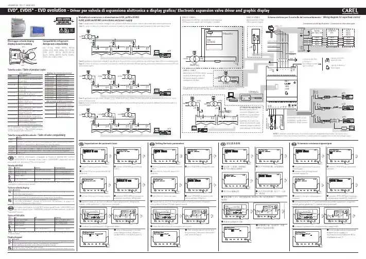
CVSTDUM0R0+050004150 - rel. 1.7 - 09.01.2013Tabella codici / Table of product codesEVD evolutioncode descriptionEVD0000E00EVD Evolution universal (tLAN)EVD0000E01EVD Evolution universal (tLAN),10 pz* (pcs)EVD0000E10EVD Evolution universal (pLAN)EVD0000E11EVD Evolution universal (pLAN),10 pz* (pcs)EVD0000E20EVD Evolution universal (RS485/Modbus®)EVD0000E21EVD Evolution universal (RS485/Modbus®), 10 pz* (pcs)EVD0000E30EVD Evolution for CAREL valves(tLAN)EVD0000E31EVD Evolution for CAREL valves(tLAN), 10 pz* (pcs)EVD0000E40EVD Evolution for CAREL valves(pLAN)EVD0000E41EVD Evolution for CAREL valves(pLAN), 10 pz* (pcs)EVD0000E50EVD Evolution for CAREL valves(RS485/Modbus®)EVD0000E51EVD Evolution for CAREL valves(RS485/Modbus®), 10 pz* (pcs)EVD0002E10EVD Evolution universaloptoisolated (pLAN)EVD0002E20EVD Evolution universaloptoisolated (RS485/Modbus®)(*) La confezione con imballo multiplo non è fornita di connettori / Th e multiple packages are not supplied with connectorsTabella compatibilità valvole / Table of valve compatibilityModel CAREL E*V****ALCOEX4; EX5; EX6; EX7; EX8 330 Hz (consigliato da CAREL/supported by CAREL ); EX8 500 Hz (da specifi che ALCO/from ALCO specifi cations )SPORLAN SEI 0.5-11; SER 1.5-20; SEI 30; SEI 50; SEH 100; SEH175Danfoss ETS 12.5-25B; ETS 50B; ETS 100B; ETS 250; ETS 400; CCM 10-20-30; CCM 40CAREL Due EXV CAREL collegate insieme / Two CAREL ExV connected together SPORLAN SER(I) G, J, K Montaggio scheda display D isplay board mountingC ompatibilità refrigeranti R efrigerant compatibilityR22; R134a; R404A; R407C; R410A; R507A; R290; R600; R600a; R717; R744; R728; R1270; R417A; R422D; R413A; R422A; R423A; R407A; R427A; R245Fa; R407F; R32; HTR01; HTR02For further information, see the “EEV system guide” (code +030220810) and the user manual (code +0300005EN) available at , under the“Literature” section.to be executed.Modalità di connessioni e alimentazione tL AN , pL AN e RS 485tL AN , pL AN and RS 485 connections and power supplyS chema elettrico per il controllo del surriscaldamento / W iring diagram for superheat controlCaso 1: applicazione di più driver collegati in rete, all’interno dello stesso quadro elettrico, alimentati dallo stesso trasformatore Case 1: a series of drivers is connected in a network, installed in the same electrical panel, powered by the same transformerCaso 2: applicazione di più driver collegati in rete, all’interno di quadri elettrici diversi, alimentati da trasformatori diversi (G0 non connesso a terra).Case 2: a series of drivers is connected in a network, installed in electrical diff erent panels, powered by diff erent transformers (G0 not connected to earth).punto di messa a terra.Case 3: a series of drivers is connected in a network, installed in electrical diff erent panels, powered by diff erent transformers with just one earth point.Per ulteriori informazioni, consultare la “Guida al sistema EEV” (codice +030220810) e il manuale d’uso (codice +03000005IT) disponibili sul sito, alla sezione “Documentazione”.procedura di prima messa in servizio.sovraccarico / Use a class 2 safety transformer, suitably protected against short-circuits and voltage surgesCASO 1/ CASE 1:alimentazione 230 Vac con modulo di emergenza/230 Vac power supply with emergency module CASO 3/ CASE 3:alimentazione 24 Vdc/ 24 Vdc power supplydisplay (accessorio/accessory)codedescriptionEVDIS00CN0Display (Chinese)EVDIS00CZ0Display (Czech)EVDIS00DE0Display (German)EVDIS00EN0Display (English)EVDIS00ES0Display (Spanish)EVDIS00FR0Display (French)EVDIS00IT0Display (Italian)EVDIS00JP0Display (Japanese)EVDIS00PL0Display (Polish)EVDIS00PT0Display (Portuguese)EVDIS00RU0Display (Russian)EVDIS00SE0Display (Swedish)altri accessori/other accessoriesEVDCON0021Kit connettori 10 pz*(connector kit 10 pcs)EVDCNV00E0Convertitore USB/tLAN(USB/tLAN converter)TRADRFE240trasformatore 35VA(35VA transformer)EVD0000UC0Modulo Ultracap(Ultracap module)C AREL INDUSTRIES HQsVia dell’Industria, 11 - 35020 Brugine - Padova (Italy)Tel.(+39)0499716611–Fax(+39)0499716600––e-mail:***************+050004150 - rel. 1.7 - 09.01.2013 CAREL si riserva la possibilità di apportare modifi che o cambiamenti ai propri prodotti senza alcun preavviso. / CAREL reserves the right to modify the features of its products without prior notice.。
SK680系列变频器使用说明书
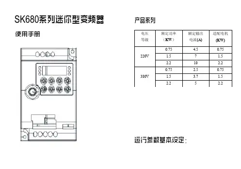
SK680系列迷你型变频器使用手册产品系列运行参数基本设定:电压等级额定功率(KW )额定输出电流(A)适配电机(KW)0.754.50.751.57 1.5220V2.210 2.20.752.50.751.53.7 1.5380V2.252.2F0基本运行参数0:操作键盘运行命令通道实施运行控制。
1:端子运行命令通道由定义为FWD、REV、JOG正转、JOG反转等功能的多功能端子实施运行控制。
0:键盘电位器通过操作键盘上的电位器来调节运行频率。
1:数字给定节由F0.08与面板频率增量相加产生运行频率,后者2:数字给定2(UP/DOWN端子调节)由外部定义为UP/DOWN功能的多功能端子的通断来改变运行频率。
3:AI1模拟给定(0~10V/0~20mA)频率设置由AI1端子输入的模拟量确定,输入模拟量范围:0~10V/0~20mA。
4:组合给定运行频率由上述各个频率给定通道的线性组合来设定,具体组合方式请参见功能码F1.22详细说明。
最大输出频率是变频器允许输出的最高频率,是加减速设定的基准。
0:零速运行1:以下限频率运行2:停机F0.08为变频器为频率数字给定初始值。
LED 个位:掉电存储0:存储变频器上电时,面板和端子频率增量初始化为上一次掉电时EEPROM 中保存的值。
1:不存储变频器上电时,面板和端子频率增量初始化为0。
LED 十位:设定频率停机后是否保持0:停机保持变频器停机时,频率设定值为最终修改值。
1:不保持变频器停机时,设定频率恢复到F0.08。
加速时间是指变频器从零频加速到最大输出频率所需时间。
0:正转实际运行方向与系统默认设定转向一致。
1:反转选择本方式时,变频器的实际输出相序将与系统默认相序相反。
2:禁止反转任何情况下,变频器只能正转运行。
该功能适用于反转运行可能会带来危险或财产损失的场合。
0:线性曲线线性曲线适用于普通恒转矩型负载,输出电压与输出频率成线性关系。
1:平方曲线平方曲线适用于风机、水泵等平方转矩型负载,以达到最佳节能效果,输出电压与输出频率成平方曲线关系。
TPS24700 01 10 11 EVM 用户指南说明书
TPS24700EVM-001TPS24701EVM-002Using the TPS24700EVM-001,TPS24701EVM-002,TPS24710EVM-003and the TPS24711EVM-004User's GuideLiterature Number:SLUU459January2011User's GuideSLUU459–January2011 TPS24700/01/10/11Evaluation Module(TPS24700EVM-001, TPS24701EVM-002,TPS24710EVM-003and theTPS24711EVM-004)This User’s Guide describes the setup and operation of the TPS24700EVM-001,TPS24701EVM-002, TPS24710EVM-003and the TPS24711EVM-004system test boards.1IntroductionThis User’s Guide describes the features of the TPS24700/01/10/11EVM.Also provided are theschematic,layout and list of materials.2DescriptionThe EVM is a3-V to20-V module using the TPS24700/01/10/11hot-swap controller with externalMOSFET.At power on,the output is power limited to control inrush current and protect the MOSFET.On an over-current condition,the controller interrupts power to the load at high speed and signals load status.Operating current,fault current and fault timer settings are hardware programmable.2.1Applications•Server–Plug-In Circuit Boards–RAID/Disk Drive•Telecom–ATCA–Micro-ATCA•General Hot Plug2.2Features•Board design covers input/output from3-V to20-V but is factory set for12-V operation.The customer can change components to operate at other voltages and currents.•Board design for50-A steady state max output.The EVM will be set up for a12-V,25-A nominal application.The datasheet design examples show how to select components for other operating setpoints.•Latch-off or re-try controller by part number.•Input/output out of operating range transient voltage protections.•Support components to be0603size where permitted by power dissipation or component ratings.•2-oz copper,4layer.•On-board ENABLE input(slide switch).2TPS24700/01/10/11Evaluation Module(TPS24700EVM-001,SLUU459–January2011 TPS24701EVM-002,TPS24710EVM-003and the TPS24711EVM-004)Submit Documentation Feedback©2011,Texas Instruments Incorporated Schematic3SchematicFigure 1.3SLUU459–January 2011TPS24700/01/10/11Evaluation Module (TPS24700EVM-001,TPS24701EVM-002,TPS24710EVM-003and the TPS24711EVM-004)Submit Documentation Feedback©2011,Texas Instruments IncorporatedOvervoltage Protection 4Overvoltage ProtectionInput protection for the TPS24700A and MOSFET consists of a15-V TVS and0.1-µF and47-µFcapacitors located close to the VIN pins.The TVS is active at16.5V S is Vishay SMAJ15A,400W,SMA package.Output protection is a fixed47-µF capacitor and a parallel0.1-µF capacitor located at the output terminals.A schottky diode on the output clamps negative going transitions.Diode MBRS3100T3,3A,100V.5ENABLE SignalSlide switch to operate ENABLE signal.The Enable signal is externally pulled to VIN through a resistor divider to set the UV to10-V.A0.1-µF capacitor will be used to help de-bounce the Enable switch.6Test PointsTest points are located on the board edge.Table1.Test PointsNAME DESCRIPTIONENUV Enable Signal4.3-V REF 4.3VPG Power Good,Signal,Low TrueFLT Fault,Signal,Low TrueSENSE Sense Resistor Voltage LowGND Scope Ground Test PointGND Scope Ground Test PointGND Scope Ground Test PointGND Scope Ground Test PointVOUT Output VoltageCT Fault Timer CapacitorPROG Program VoltageSET Current Limit Set PointGATE Gate SignalVIN Input Voltage Power Supply4TPS24700/01/10/11Evaluation Module(TPS24700EVM-001,SLUU459–January2011 TPS24701EVM-002,TPS24710EVM-003and the TPS24711EVM-004)Submit Documentation Feedback©2011,Texas Instruments Incorporated Jumpers 7JumpersNone8Indicator LEDSA4.3-V Zener is used to control the voltage applied to the EN signal.It is also used to limit the voltage range on the LEDs.A bipolar signal transistor is used to turn on the LED while keeping the PG and FLT signals less than0.3-V active.Table2.Indicator LED ColorsSIGNAL LED COLORPG GreenFLT Red9Disable Power LimitingPower limiting can be disabled by leaving the PROG pin open(no programming resistor).The soft-start time can be controlled by a gate capacitor and series1-kΩresistor.See Not Installed.10Not Installed•D6is installed if the VGS needs to be limited.The zener voltage rating set VGS max.•R19,C9installed if the soft start is not controlled by power limiting but by gate current and the selected C9Where C=I x T/V.Example,for10-ms start on a12-V board,C=30µA x10ms/25V,C=12nF.5 SLUU459–January2011TPS24700/01/10/11Evaluation Module(TPS24700EVM-001,TPS24701EVM-002,TPS24710EVM-003and the TPS24711EVM-004) Submit Documentation Feedback©2011,Texas Instruments IncorporatedEVM Assembly Drawings and Layout 11EVM Assembly Drawings and LayoutFigure2.Board Topyer16TPS24700/01/10/11Evaluation Module(TPS24700EVM-001,SLUU459–January2011 TPS24701EVM-002,TPS24710EVM-003and the TPS24711EVM-004)Submit Documentation Feedback©2011,Texas Instruments Incorporated EVM Assembly Drawings and Layoutyer2Figure5.Board Bottom7 SLUU459–January2011TPS24700/01/10/11Evaluation Module(TPS24700EVM-001,TPS24701EVM-002,TPS24710EVM-003and the TPS24711EVM-004) Submit Documentation Feedback©2011,Texas Instruments IncorporatedList of Materials 12List of MaterialsTable3.List of Materials(1)(2)(3)(4)REF-004-003-002-001DESCRIPTION PART NUMBER MFRDESC1,C6,Capacitor,ceramic,100V,X7R,10%,0.1µF,STD STD 4444C7,C80805C9Capacitor,ceramic,100V,X7R,10%,0.1µF,STD STD 00000805C2Capacitor,ceramic,100V,X7R,10%,1000pF,STD STD 11110603C3,C5Capacitor,aluminum,80VDC,±20%,68µF,EEVFK1K680Q Panasonic 22220.670inch x0.750inchC4Capacitor,ceramic,16V,X7R,10%,68nF,STD STD 111106031111D1Diode,[uni-]directional TVS,1500W,SMC SMCJ18A-13-F Diodes1111D2Diode,Zener,4.3V,SOT23MMBZ5229B Motorola1111D3Diode,Schottky,3A,40V,SMC MBRS330T3G On Semi1111D4Diode,LED,green,0.114inch x0.049inch LN1371G PanasonicD5Diode,LED,ultra bright red,0.114inch x0.049LN1271RAL Panasonic 1111inchD6Diode,Zener,planar power,500mW,8.2V,BZT52C8V2-7Vishay 0000SOD-123J1,J2,Lug,copper,35A,0.380inch x1.020inch CX35-36Panduit 4444J3,J4Q1,Q2MOSFET,N-channel,25V,37A,1.3mΩ,QFN CSD16401Q5A-R Ciclon 22225x6mm2222Q3,Q4Bipolar,PNP,40V,200mA,SOT23MMBT3906LT1On Semi1111R1Resistor,chip,1/16W,1%,133kΩ,0603STD STDR11,Resistor,chip,1/16W,5%,10kΩ,0603STD STD 2222R15R12,Resistor,chip,1/16W,5%,20kΩ,0603STD STD 2222R16R13,Resistor,chip,1/16W,1%,1kΩ,0603STD STD 2222R170000R19Resistor,chip,1/16W,1%,1kΩ,0603STD STDR14,Resistor,chip,1/10W,5%,300Ω,0805STD STD 2222R181111R2Resistor,chip,1/16W,1%,22kΩ,0603STD STD1100R3Resistor,chip,1/16W,1%,75kΩ,0603STD STDR4Resistor,metal strip,0.01Ohms,2W,1%,0.01LCR-LRF2512-IRC 0000Ω,251201-R010-FR5Resistor,power metal strip,3W,±x1%,0.001Ω,WSR-3Vishay Dale 111145271111R8Resistor,chip,0.5W,1%,499Ω,2512STD STD2222R9,R10Resistor,chip,1/16W,1%,10Ω,0603Std Std(1)These assemblies are ESD sensitive,ESD precautions shall be observed.(2)These assemblies must be clean and free from flux and all e of no clean flux is not acceptable.(3)These assemblies must comply with workmanship standards IPC-A-610Class2.(4)Ref designators marked with an asterisk('**')cannot be substituted.All other components can be substituted with equivalentMFG's components.8TPS24700/01/10/11Evaluation Module(TPS24700EVM-001,SLUU459–January2011 TPS24701EVM-002,TPS24710EVM-003and the TPS24711EVM-004)Submit Documentation Feedback©2011,Texas Instruments Incorporated List of MaterialsTable3.List of Materials(1)(2)(3)(4)(continued)REF-004-003-002-001DESCRIPTION PART NUMBER MFRDESS1Switch,SPDT,slide,PC mount,500mA,0.40009.03201.02EAO 1111inch x0.100inchTP1,Test point,white,thru hole,0.125inch x0.1255012KeystoneTP2,inchTP3,TP4,TP5,TP6,TP7,14141414TP8,TP9,TP10,TP11,TP12,TP13,TP14U1 2.5V to20V Positive Voltage Power-Limiting TPS24700DGK TI 0001Hotswap Controller,VSSOP-8U1 2.5V to20V Positive Voltage Power-Limiting TPS24701DGK TI 0010Hotswap Controller,VSSOP-8U2 2.5V to20V Positive Voltage Power-Limiting TPS24710DGS TI 0100Hotswap Controller,VSSOP-10U2 2.5to20V Positive Voltage Power-Limiting TPS24711DGS TI 1000Hotswap Controller,VSSOP-101111--PCB,4.82inch x3.3inch x0.062inch PCB Any4444Bumpons,cylindrical,black SJ5514-03M4444Screw,panhead#10-320.500inch4444Washer,flat#104444Washer,split M54444Nut,hex#10-329 SLUU459–January2011TPS24700/01/10/11Evaluation Module(TPS24700EVM-001,TPS24701EVM-002,TPS24710EVM-003and the TPS24711EVM-004) Submit Documentation Feedback©2011,Texas Instruments IncorporatedEvaluation Board/Kit Important NoticeTexas Instruments(TI)provides the enclosed product(s)under the following conditions:This evaluation board/kit is intended for use for ENGINEERING DEVELOPMENT,DEMONSTRATION,OR EVALUATION PURPOSES ONLY and is not considered by TI to be a finished end-product fit for general consumer use.Persons handling the product(s)must have electronics training and observe good engineering practice standards.As such,the goods being provided are not intended to be complete in terms of required design-,marketing-,and/or manufacturing-related protective considerations, including product safety and environmental measures typically found in end products that incorporate such semiconductor components or circuit boards.This evaluation board/kit does not fall within the scope of the European Union directives regarding electromagnetic compatibility,restricted substances(RoHS),recycling(WEEE),FCC,CE or UL,and therefore may not meet the technical requirements of these directives or other related directives.Should this evaluation board/kit not meet the specifications indicated in the User’s Guide,the board/kit may be returned within30 days from the date of delivery for a full refund.THE FOREGOING WARRANTY IS THE EXCLUSIVE WARRANTY MADE BY SELLER TO BUYER AND IS IN LIEU OF ALL OTHER WARRANTIES,EXPRESSED,IMPLIED,OR STATUTORY,INCLUDING ANY WARRANTY OF MERCHANTABILITY OR FITNESS FOR ANY PARTICULAR PURPOSE.The user assumes all responsibility and liability for proper and safe handling of the goods.Further,the user indemnifies TI from all claims arising from the handling or use of the goods.Due to the open construction of the product,it is the user’s responsibility to take any and all appropriate precautions with regard to electrostatic discharge.EXCEPT TO THE EXTENT OF THE INDEMNITY SET FORTH ABOVE,NEITHER PARTY SHALL BE LIABLE TO THE OTHER FOR ANY INDIRECT,SPECIAL,INCIDENTAL,OR CONSEQUENTIAL DAMAGES.TI currently deals with a variety of customers for products,and therefore our arrangement with the user is not exclusive.TI assumes no liability for applications assistance,customer product design,software performance,or infringement of patents or services described herein.Please read the User’s Guide and,specifically,the Warnings and Restrictions notice in the User’s Guide prior to handling the product.This notice contains important safety information about temperatures and voltages.For additional information on TI’s environmental and/or safety programs,please contact the TI application engineer or visit /esh.No license is granted under any patent right or other intellectual property right of TI covering or relating to any machine,process,or combination in which such TI products or services might be or are used.FCC WarningThis evaluation board/kit is intended for use for ENGINEERING DEVELOPMENT,DEMONSTRATION,OR EVALUATION PURPOSES ONLY and is not considered by TI to be a finished end-product fit for general consumer use.It generates,uses,and can radiate radio frequency energy and has not been tested for compliance with the limits of computing devices pursuant to part15 of FCC rules,which are designed to provide reasonable protection against radio frequency interference.Operation of this equipment in other environments may cause interference with radio communications,in which case the user at his own expense will be required to take whatever measures may be required to correct this interference.EVM Warnings and RestrictionsIt is important to operate this EVM within the input voltage range of3V to20V and the output voltage range of3V to20V. Exceeding the specified input range may cause unexpected operation and/or irreversible damage to the EVM.If there are questions concerning the input range,please contact a TI field representative prior to connecting the input power.Applying loads outside of the specified output range may result in unintended operation and/or possible permanent damage to the EVM.Please consult the EVM User's Guide prior to connecting any load to the EVM output.If there is uncertainty as to the load specification,please contact a TI field representative.During normal operation,some circuit components may have case temperatures greater than50°C.The EVM is designed to operate properly with certain components above50°C as long as the input and output ranges are maintained.These components include but are not limited to linear regulators,switching transistors,pass transistors,and current sense resistors.These types of devices can be identified using the EVM schematic located in the EVM User's Guide.When placing measurement probes near these devices during operation,please be aware that these devices may be very warm to the touch.Mailing Address:Texas Instruments,Post Office Box655303,Dallas,Texas75265Copyright©2011,Texas Instruments IncorporatedIMPORTANT NOTICETexas Instruments Incorporated and its subsidiaries(TI)reserve the right to make corrections,modifications,enhancements,improvements, and other changes to its products and services at any time and to discontinue any product or service without notice.Customers should obtain the latest relevant information before placing orders and should verify that such information is current and complete.All products are sold subject to TI’s terms and conditions of sale supplied at the time of order acknowledgment.TI warrants performance of its hardware products to the specifications applicable at the time of sale in accordance with TI’s standard warranty.Testing and other quality control techniques are used to the extent TI deems necessary to support this warranty.Except where mandated by government requirements,testing of all parameters of each product is not necessarily performed.TI assumes no liability for applications assistance or customer product design.Customers are responsible for their products and applications using TI components.To minimize the risks associated with customer products and applications,customers should provide adequate design and operating safeguards.TI does not warrant or represent that any license,either express or implied,is granted under any TI patent right,copyright,mask work right, or other TI intellectual property right relating to any combination,machine,or process in which TI products or services are rmation published by TI regarding third-party products or services does not constitute a license from TI to use such products or services or a warranty or endorsement e of such information may require a license from a third party under the patents or other intellectual property of the third party,or a license from TI under the patents or other intellectual property of TI.Reproduction of TI information in TI data books or data sheets is permissible only if reproduction is without alteration and is accompanied by all associated warranties,conditions,limitations,and notices.Reproduction of this information with alteration is an unfair and deceptive business practice.TI is not responsible or liable for such altered rmation of third parties may be subject to additional restrictions.Resale of TI products or services with statements different from or beyond the parameters stated by TI for that product or service voids all express and any implied warranties for the associated TI product or service and is an unfair and deceptive business practice.TI is not responsible or liable for any such statements.TI products are not authorized for use in safety-critical applications(such as life support)where a failure of the TI product would reasonably be expected to cause severe personal injury or death,unless officers of the parties have executed an agreement specifically governing such use.Buyers represent that they have all necessary expertise in the safety and regulatory ramifications of their applications,and acknowledge and agree that they are solely responsible for all legal,regulatory and safety-related requirements concerning their products and any use of TI products in such safety-critical applications,notwithstanding any applications-related information or support that may be provided by TI.Further,Buyers must fully indemnify TI and its representatives against any damages arising out of the use of TI products in such safety-critical applications.TI products are neither designed nor intended for use in military/aerospace applications or environments unless the TI products are specifically designated by TI as military-grade or"enhanced plastic."Only products designated by TI as military-grade meet military specifications.Buyers acknowledge and agree that any such use of TI products which TI has not designated as military-grade is solely at the Buyer's risk,and that they are solely responsible for compliance with all legal and regulatory requirements in connection with such use. TI products are neither designed nor intended for use in automotive applications or environments unless the specific TI products are designated by TI as compliant with ISO/TS16949requirements.Buyers acknowledge and agree that,if they use any non-designated products in automotive applications,TI will not be responsible for any failure to meet such requirements.Following are URLs where you can obtain information on other Texas Instruments products and application solutions:Products ApplicationsAudio /audio Communications and Telecom /communicationsAmplifiers Computers and Peripherals /computersData Converters Consumer Electronics /consumer-appsDLP®Products Energy and Lighting /energyDSP Industrial /industrialClocks and Timers /clocks Medical /medicalInterface Security /securityLogic Space,Avionics and Defense /space-avionics-defense Power Mgmt Transportation and /automotiveAutomotiveMicrocontrollers Video and Imaging /videoRFID Wireless /wireless-appsRF/IF and ZigBee®Solutions /lprfTI E2E Community Home Page Mailing Address:Texas Instruments,Post Office Box655303,Dallas,Texas75265Copyright©2011,Texas Instruments IncorporatedTPS24700EVM-001TPS24701EVM-002。
航宇md680变频器说明书

航宇md680变频器说明书篇一:标题:航宇MD680变频器说明书正文:航宇MD680变频器是一款高性能、多功能的变频器,广泛应用于工业自动化、楼宇自动化、电机节能等领域。
本说明书详细介绍了航宇MD680变频器的使用方法、参数设置、维护保养等内容,帮助用户更好地使用和管理变频器,提高生产效率,降低能源消耗。
一、介绍航宇MD680变频器是一款专为工业自动化和电机节能而设计的变频器。
它具有高性能、多功能、可靠性高等特点,可广泛应用于各种工业自动化设备、楼宇自动化设备、电机节能等领域。
二、使用方法1. 安装调试将MD680变频器安装在需要使用的位置,并确保其牢固稳定。
连接MD680变频器的电源和数据连接线,确保连接处牢固可靠。
然后,根据MD680变频器的使用手册中的说明进行调试。
2. 设置参数根据MD680变频器的使用需求,设置相关的参数。
例如,可以设置变频器的调速范围、速度精度、频率响应、转矩输出等参数。
在设置参数时,应确保参数的准确性和合理性,以确保设备的正常运行和效率提高。
3. 运行维护在运行过程中,需要定期对MD680变频器进行维护和保养。
例如,清洁变频器的内部和外部,检查变频器的电缆和连接处是否牢固可靠,确保设备的正常运行和安全性。
三、参数设置1. 调速范围MD680变频器有多种调速方式,例如线性调速、闭环调速、模拟调速等。
在设置调速范围时,应根据设备的实际需求和运行状态进行调整。
例如,对于线性调速,可以设置适当的速度范围;对于闭环调速,可以设置适当的速度范围和反馈参数;对于模拟调速,可以设置适当的模拟输入参数。
2. 速度精度MD680变频器的速度精度越高,越能够提高设备的效率和精度。
在设置速度精度时,应根据设备的实际需求和运行状态进行调整。
例如,对于一般工业自动化设备,可以设置较高的速度精度;对于楼宇自动化设备,可以设置较低的速度精度。
3. 频率响应MD680变频器的频率响应越准确,越能够提高设备的效率和精度。
遥控器复制机英文版说明书

A Brief Duplicator User's GuideA.NORMAL COPY1.please sturn on the power and press the 5th key once------remote copy2.press the 1st key once----------input 1 key3.begin to input the client's 1st key(press the key until the frequency displayed )------- ISN data4.press the 5th key once-------input 1 key again5.input the client's1st key again--------ISN data6.press the 5th key once------input 2 key7.input the client's 2nd key------ISN data8.press the 5th key once--------input 3 key9.input the client's 3rd key------ISN data10.The rest deduced ,having finished the inputingprocess,press the 5th key twicees -----use NO.''x'' remote11.having inserted No.''x'' remote,press the 5th key twice------write ok12.pull out the remote,press the duplicator 4th key---------FREQ MHz13.put the copied remote on the duplicator,press any key once-----appearing frequency14.put the new remote on the duplicator,use ceramic aligner tool to turn round white capacitance until the digtal reach the copied remote15.having finished the adjustment,press the 1st and 2rd once at the same time . the light flash once,then press any key ,the light -light-,overB.SINGKEY COPY1.turn on the power,press the 5th key twice-----normal copy2.press the 3rd once-------singkey copy3.press the 5th once------input 1 key4.input the 1st key once------input 1key 0035.input the 1st key the 2nd time ------input 1key 0136.input the 1st key the 3rd time-------input 1key 0237.go on inputing until--------input 2key 0138.input the 2nd key once-----input 2key 0239.all key inputted,press the duplicator 5th key twice-----use No.''x''remot e10.the other steps like the ''normal copy''C.Reread/recopy(SCP)this function is used to recopy the having copied remote1.turn on the power ,press the 5th key once ------remote copy2.press the 2nd key once------inline remote3.insert the client's having copied remote,press the 5th key once-----write to remot4.pull out the client's remote, press the 5th key once------input NO.''X'' remote5.insert the new blank No''x'' remote,press the 5th key twice-----write ok6.pull out the new remote,begin to adjust the frequency,like the ''normal copy''7.press the 1st and 2nd key of the new remote at the same time ,then press any key the light light,ok ,over.D.No.3 remote copy(rolling code series)1.turn on the power,input all key of the client's remote,like the ''normal copy''2.Notice : some of the client's remotes are two key,even one key,you must input five key(any key is ok)3.after you finish inputing, press the 5th key twice ,the duplicator begin to scan,if the decode scaning is succcessful,---------completely copy;if failed ,the scaning can't be stopped ,or the duplicator displayes--------input 1key4.if display(completely copy),press the 5th key twice-----input No.3 remote5.insert the new blank remote(No.3),press the 4th key(+1),then press the 5th key ------write ok6.pull out the new copiedremote,begin to adjust the frequency,like the ''normal copy''7.if the new coplied remote is 5 keyes,please press it's 5th key;if theremote 5 keyes,press the 1st and 2nd key once at the same time,then press any key ,the light lights. endNotice:Please intercopy with the client's old remote ,or it can't be usedOther question please visit 。
Eaton Moeller PKZM01 660V-690V 1.1 kW 保护电路断路器说明说明书
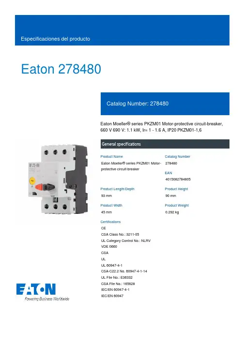
Eaton 278480Eaton Moeller® series PKZM01 Motor-protective circuit-breaker, 660 V 690 V: 1.1 kW, Ir= 1 - 1.6 A, IP20 PKZM01-1,6General specificationsEaton Moeller® series PKZM01 Motor-protective circuit-breaker278480401508278480593 mm 90 mm 45 mm 0.292 kgCECSA Class No.: 3211-05 UL Category Control No.: NLRV VDE 0660 CSA ULUL 60947-4-1CSA-C22.2 No. 60947-4-1-14 UL File No.: E36332 CSA File No.: 165628 IEC/EN 60947-4-1 IEC/EN 60947Product NameCatalog Number EANProduct Length/Depth Product Height Product Width Product Weight Certifications1.6 A2 x (1 - 6) mm², ferrule to DIN 462281 x (1 - 6) mm², ferrule to DIN 46228Is the panel builder's responsibility. The specifications for the switchgear must be observed.25 °C0.55 kWMeets the product standard's requirements.Is the panel builder's responsibility. The specifications for the switchgear must be observed.Does not apply, since the entire switchgear needs to be evaluated.1.6 A (3 contacts in series), DC-5 up to 250V1.6 A, AC-3 up to 440 V10 mm40 °C50 kAMeets the product standard's requirements.40 °C25 A eaton-manual-motor-starters-characteristic-characteristic-curve-006.eps eaton-manual-motor-starters-characteristic-characteristic-curve-008.epsDA-DC-00004884.pdfDA-DC-00004914.pdfETN.PKZM01-1,6IL122012ZUIL03407011ZIL03402034ZIL122023ZUDA-CS-pkzm01DA-CD-pkzm01Rated operational current for specified heat dissipation (In) Terminal capacity (flexible with ferrule)10.11 Short-circuit ratingAmbient operating temperature (enclosed) - minRated operational power at AC-3, 380/400 V, 50 Hz10.4 Clearances and creepage distances10.12 Electromagnetic compatibility10.2.5 LiftingSwitching capacityStripping length (main cable)Ambient operating temperature (enclosed) - maxRated short-circuit breaking capacity Icu at 400 V AC 10.2.3.1 Verification of thermal stability of enclosures Ambient storage temperature - minAdjustment range undelayed short-circuit release - max 10.8 Connections for external conductors Characteristic curve Declarations of conformity eCAD model Instrucciones de instalación Manuales y guías de uso mCAD modelIs the panel builder's responsibility.Assigned motor power at 575/600 V, 60 Hz, 3-phase0.75 HPProtectionFinger and back-of-hand proof, Protection against direct contact when actuated from front (EN 50274)Actuator typePush buttonRated operational power at AC-3, 440 V, 50 Hz0.55 kWAmbient operating temperature - max55 °CRated operational power at AC-3, 220/230 V, 50 Hz0.25 kWClimatic proofingDamp heat, constant, to IEC 60068-2-78Damp heat, cyclic, to IEC 60068-2-30Device constructionBuilt-in device fixed built-in techniqueFeaturesPhase-failure sensitivity (according to IEC/EN 60947-4-1, VDE 0660 Part 102)Lifespan, electrical50,000 operations (at 400V, AC-3)Static heat dissipation, non-current-dependent Pvs0 WElectrical connection type of main circuitScrew connection10.9.3 Impulse withstand voltageIs the panel builder's responsibility.Number of polesThree-poleAmbient operating temperature - min-25 °C10.6 Incorporation of switching devices and componentsDoes not apply, since the entire switchgear needs to be evaluated.10.5 Protection against electric shockDoes not apply, since the entire switchgear needs to be evaluated.Mounting positionCan be snapped on to IEC/EN 60715 top-hat rail with 7.5 or15 mm height.Rated uninterrupted current (Iu)1.6 ATripping characteristicOverload trigger: tripping class 10 AShort-circuit release24.8 A, Irm, Setting range max.Basic device fixed 15.5 x Iu, Trip Blocks± 20% tolerance, Trip blocks10.13 Mechanical functionThe device meets the requirements, provided the information in the instruction leaflet (IL) is observed.10.2.6 Mechanical impactDoes not apply, since the entire switchgear needs to be evaluated.10.9.4 Testing of enclosures made of insulating materialIs the panel builder's responsibility.10.3 Degree of protection of assembliesDoes not apply, since the entire switchgear needs to be evaluated.Heat dissipation per pole, current-dependent Pvid1.79 WOperating frequency25 Operations/hProduct categoryMotor protective circuit breakerShort-circuit current rating (group protection)600 A, 600 V High Fault, max. Fuse, SCCR (UL/CSA)50 kA, 600 V High Fault, Fuse, SCCR (UL/CSA)600 A, 600 V High Fault, max. CB, SCCR (UL/CSA)50 kA, 600 V High Fault, CB, SCCR (UL/CSA)Overload release current setting - min1 AEquipment heat dissipation, current-dependent Pvid5.36 WHeat dissipation capacity Pdiss0 WRated operational current (Ie)1.6 AAssigned motor power at 460/480 V, 60 Hz, 3-phase0.75 HPSuitable forAlso motors with efficiency class IE3Branch circuit: Manual type E if used with terminal, or suitable for group installations, (UL/CSA)Internal resistance700 mΩTemperature compensation-25 - 55 °C, Operating range≤ 0.25 %/K, residual error for T > 40°-5 - 40 °C to IEC/EN 60947, VDE 0660Terminal capacity (solid)1 x (1 - 6) mm²2 x (1 - 6) mm²Rated frequency - min50 HzShort-circuit current60 kA DC, up to 250 V DC, Main conducting pathsPower loss5.36 W10.2.3.2 Verification of resistance of insulating materials to normal heatMeets the product standard's requirements.10.2.3.3 Resist. of insul. mat. to abnormal heat/fire by internal elect. effectsMeets the product standard's requirements.Lifespan, mechanical50,000 Operations (Main conducting paths)Terminal capacity (solid/stranded AWG)18 - 10Overload release current setting - max1.6 A10.9.2 Power-frequency electric strengthIs the panel builder's responsibility.Overvoltage categoryIIIDegree of protectionTerminals: IP00IP20Rated frequency - max60 HzSwitch off techniqueThermomagneticAmbient storage temperature - max80 °CAdjustment range undelayed short-circuit release - min25 APollution degree310.7 Internal electrical circuits and connectionsIs the panel builder's responsibility.Rated impulse withstand voltage (Uimp)6000 V ACConnectionScrew terminals10.10 Temperature riseThe panel builder is responsible for the temperature rise calculation. Eaton will provide heat dissipation data for the devices.FunctionsPhase failure sensitiveMotor protectionTightening torque1.7 Nm, Screw terminals, Main cableRated operational voltage (Ue) - min690 VAssigned motor power at 230/240 V, 60 Hz, 1-phase0.1 HP10.2.2 Corrosion resistanceMeets the product standard's requirements.10.2.4 Resistance to ultra-violet (UV) radiationMeets the product standard's requirements.Eaton Corporation plc Eaton House30 Pembroke Road Dublin 4, Ireland © 2023 Eaton. Todos los derechos reservados. Eaton is a registered trademark.All other trademarks areproperty of their respectiveowners./socialmediaMeets the product standard's requirements.25 g, Mechanical, according to IEC/EN 60068-2-27, Half-sinusoidal shock 10 ms690 V Max. 2000 m10.2.7 InscriptionsShock resistanceRated operational voltage (Ue) - max Altitude。
TDK EPC 680型号电容器说明书
Dimensions: [mm]Scale - 4:174404084680BC74404084680T e m p e r a t u r eT pT L74404084680Cautions and Warnings:The following conditions apply to all goods within the product series of WE-LQS of Würth Elektronik eiSos GmbH & Co. KG:General:•This electronic component is designed and manufactured for use in general electronic equipment.•Würth Elektronik must be asked for written approval (following the PPAP procedure) before incorporating the components into any equipment in fields such as military, aerospace, aviation, nuclear control, submarine, transportation (automotive control, train control, ship control), transportation signal, disaster prevention, medical, public information network etc. where higher safety and reliability are especially required and/or if there is the possibility of direct damage or human injury.•Electronic components that will be used in safety-critical or high-reliability applications, should be pre-evaluated by the customer. •The component is designed and manufactured to be used within the datasheet specified values. If the usage and operation conditions specified in the datasheet are not met, the wire insulation may be damaged or dissolved.•Do not drop or impact the components, the component may be damaged.•Würth Elektronik products are qualified according to international standards, which are listed in each product reliability report. Würth Elektronik does not warrant any customer qualified product characteristics beyond Würth Elektroniks’ specifications, for its validity and sustainability over time.•The responsibility for the applicability of the customer specific products and use in a particular customer design is always within the authority of the customer. All technical specifications for standard products also apply to customer specific products.Product specific:Soldering:•The solder profile must comply with the technical product specifications. All other profiles will void the warranty.•All other soldering methods are at the customers’ own risk.•Strong forces which may affect the coplanarity of the components’ electrical connection with the PCB (i.e. pins), can damage the part, resulting in avoid of the warranty.Cleaning and Washing:•Washing agents used during the production to clean the customer application might damage or change the characteristics of the wire insulation, marking or plating. Washing agents may have a negative effect on the long-term functionality of the product.•Using a brush during the cleaning process may break the wire due to its small diameter. Therefore, we do not recommend using a brush during the PCB cleaning process.Potting:•If the product is potted in the customer application, the potting material may shrink or expand during and after hardening. Shrinking could lead to an incomplete seal, allowing contaminants into the core. Expansion could damage the components. We recommend a manual inspection after potting to avoid these effects.Storage Conditions:• A storage of Würth Elektronik products for longer than 12 months is not recommended. Within other effects, the terminals may suffer degradation, resulting in bad solderability. Therefore, all products shall be used within the period of 12 months based on the day of shipment.•Do not expose the components to direct sunlight.•The storage conditions in the original packaging are defined according to DIN EN 61760-2.•The storage conditions stated in the original packaging apply to the storage time and not to the transportation time of the components. Packaging:•The packaging specifications apply only to purchase orders comprising whole packaging units. If the ordered quantity exceeds or is lower than the specified packaging unit, packaging in accordance with the packaging specifications cannot be ensured. Handling:•Violation of the technical product specifications such as exceeding the nominal rated current will void the warranty.•Applying currents with audio-frequency signals may result in audible noise due to the magnetostrictive material properties.•The temperature rise of the component must be taken into consideration. The operating temperature is comprised of ambient temperature and temperature rise of the component.The operating temperature of the component shall not exceed the maximum temperature specified.These cautions and warnings comply with the state of the scientific and technical knowledge and are believed to be accurate and reliable.However, no responsibility is assumed for inaccuracies or incompleteness.Würth Elektronik eiSos GmbH & Co. KGEMC & Inductive SolutionsMax-Eyth-Str. 174638 WaldenburgGermanyCHECKED REVISION DATE (YYYY-MM-DD)GENERAL TOLERANCE PROJECTIONMETHODChrB002.0002023-03-27DIN ISO 2768-1mDESCRIPTIONWE-LQS SMT Semi-ShieldedPower Inductor ORDER CODE74404084680SIZE/TYPE BUSINESS UNIT STATUS PAGEImportant NotesThe following conditions apply to all goods within the product range of Würth Elektronik eiSos GmbH & Co. KG:1. General Customer ResponsibilitySome goods within the product range of Würth Elektronik eiSos GmbH & Co. KG contain statements regarding general suitability for certain application areas. These statements about suitability are based on our knowledge and experience of typical requirements concerning the areas, serve as general guidance and cannot be estimated as binding statements about the suitability for a customer application. The responsibility for the applicability and use in a particular customer design is always solely within the authority of the customer. Due to this fact it is up to the customer to evaluate, where appropriate to investigate and decide whether the device with the specific product characteristics described in the product specification is valid and suitable for the respective customer application or not.2. Customer Responsibility related to Specific, in particular Safety-Relevant ApplicationsIt has to be clearly pointed out that the possibility of a malfunction of electronic components or failure before the end of the usual lifetime cannot be completely eliminated in the current state of the art, even if the products are operated within the range of the specifications.In certain customer applications requiring a very high level of safety and especially in customer applications in which the malfunction or failure of an electronic component could endanger human life or health it must be ensured by most advanced technological aid of suitable design of the customer application that no injury or damage is caused to third parties in the event of malfunction or failure of an electronic component. Therefore, customer is cautioned to verify that data sheets are current before placing orders. The current data sheets can be downloaded at .3. Best Care and AttentionAny product-specific notes, cautions and warnings must be strictly observed. Any disregard will result in the loss of warranty.4. Customer Support for Product SpecificationsSome products within the product range may contain substances which are subject to restrictions in certain jurisdictions in order to serve specific technical requirements. Necessary information is available on request. In this case the field sales engineer or the internal sales person in charge should be contacted who will be happy to support in this matter.5. Product R&DDue to constant product improvement product specifications may change from time to time. As a standard reporting procedure of the Product Change Notification (PCN) according to the JEDEC-Standard inform about minor and major changes. In case of further queries regarding the PCN, the field sales engineer or the internal sales person in charge should be contacted. The basic responsibility of the customer as per Section 1 and 2 remains unaffected.6. Product Life CycleDue to technical progress and economical evaluation we also reserve the right to discontinue production and delivery of products. As a standard reporting procedure of the Product Termination Notification (PTN) according to the JEDEC-Standard we will inform at an early stage about inevitable product discontinuance. According to this we cannot guarantee that all products within our product range will always be available. Therefore it needs to be verified with the field sales engineer or the internal sales person in charge about the current product availability expectancy before or when the product for application design-in disposal is considered. The approach named above does not apply in the case of individual agreements deviating from the foregoing for customer-specific products.7. Property RightsAll the rights for contractual products produced by Würth Elektronik eiSos GmbH & Co. KG on the basis of ideas, development contracts as well as models or templates that are subject to copyright, patent or commercial protection supplied to the customer will remain with Würth Elektronik eiSos GmbH & Co. KG. Würth Elektronik eiSos GmbH & Co. KG does not warrant or represent that any license, either expressed or implied, is granted under any patent right, copyright, mask work right, or other intellectual property right relating to any combination, application, or process in which Würth Elektronik eiSos GmbH & Co. KG components or services are used.8. General Terms and ConditionsUnless otherwise agreed in individual contracts, all orders are subject to the current version of the “General Terms and Conditions of Würth Elektronik eiSos Group”, last version available at .Würth Elektronik eiSos GmbH & Co. KGEMC & Inductive SolutionsMax-Eyth-Str. 174638 WaldenburgGermanyCHECKED REVISION DATE (YYYY-MM-DD)GENERAL TOLERANCE PROJECTIONMETHODChrB002.0002023-03-27DIN ISO 2768-1mDESCRIPTIONWE-LQS SMT Semi-ShieldedPower Inductor ORDER CODE74404084680SIZE/TYPE BUSINESS UNIT STATUS PAGE。
电流互感器型号含义之欧阳引擎创编
电流互感器型号含义欧阳引擎(2021.01.01)电流互感器型号:(d%h1E(K M 第一字母:L—电流互感器Q1M y#V n i L:q.W0q第二字母:A—穿墙式;Z—支柱式;M—母线式;D—单匝贯穿式;V—结构倒置式;J—零序接地检测用;W—抗污秽;R—绕组裸露式I n n(J ^/j K C"q 第三字母:Z—环氧树脂浇注式;C—瓷绝缘;Q—气体绝缘介质;W—与微机保护专用 E L7e*M9^%L 第四数字:B—带保护级;C—差动保护;D—D级;Q—加强型;J—加强型V ?} ~)w0d ] ~ 第五数字:电压等级产品序号LZZBJ910A3GL 电流互感器 Current transformer Z 支柱式 Post type Z 浇注式 Casting type B 带保护级 Wity protective class J 加强型 Reinforced type9 设计序号 Design Number10 额定电压(kV) Highest voltage for equipment(kV)A3G 结构代号 Structure codeLFZ10QL 电流互感器 Current transformer F 复匝式Z 浇注式 Casting type 10 额定电压(kV) Highest voltage for equipment(kV) Q 结构代号 Structure codeLZZ10L 电流互感器 Current transformer Z 支柱式 Post type Z 浇注式 Casting type10 额定电压(kV) Highest voltage for equipment(kV)LMZB710GYW1L 电流互感器 Current transformer M 母线式 Busbar type Z 浇注式 Casting typeB 带保护级 Wity protective class7 设计序号 Design Number 10 额定电压(kV) Highest voltage for equipment(kV)GYW1 高原污秽 Plateau DirtyLDZB610QL 电流互感器 Current transformer D 单匝式Z 浇注式 Casting typeB 带保护级 Wity protective class6 设计序号 Design Number 10 额定电压(kV) Highest voltage for equipment(kV) Q 结构代号 Structure code LDJ210L 电流互感器 Current transformer D 带触头盒J 加强型 Reinforced type 6 设计序号 Design Number 10 额定电压(kV) Highest voltage for equipment(kV)LZZJ10L 电流互感器 Current transformer Z 支柱式 Post type Z 浇注式 Casting type J 加强型 Reinforced type10 额定电压(kV) Highest voltage for equipment(kV)LFSQ10QL 电流互感器 Current transformer F 封闭式 Hermetical type S 手车式 Handcart type Q 加强型 Reinforced type 10 额定电压(kV) Highest voltage for equipment(kV) Q 结构代号 Structure codeLCZ35QL 电流互感器 Current transformer C 手车式 Handcart type Z 浇注式 Casting type 35 额定电压(kV ) Highest voltage for equipment(kV) Q 结构代号 Structure codeJDZ(X)3,6,10J 电压互感器 V oltage transformer D 单相 Single phase Z 浇注式 Casting type X 带剩余电压绕组 With residual voltage winding3,6,10 电压等级(kV) V oltage class(kV)JDZ(X)103,6,10J 电压互感器 V oltage transformer D 单相 Single phase Z 浇注式 Casting type X 带剩余电压绕组 With residual voltage winding 10 设计序号 Design Number 3,6,10 电压等级(kV) V oltage class(kV)JDZF710GYW1J 电压互感器 V oltage transformer D 单相 Single phase Z 浇注式 Casting typeF 带剩余电压绕组 With residual voltage winding7 设计序号 Design Number 10 电压等级(kV) V oltage class(kV) GYW1 高原污秽 Plateau Dirty。
欧特斯顿9E XL系列10kVA 8kW无线电源说明书
Eaton 9E10KIXLSAI Eaton 9E XL, 10 kVA, 8 kW, Entrada: cableada, Salida:cableada, torreEspecificaciones generalesNombre del producto N.º de catálogoSAI Eaton 9E9E10KIXLUPC Longitud/profundidad de producto74317206768561.29 cmAltura del producto Anchura del producto70.85 cm26.24 cmPeso del producto Conformidad(es)28.86 kg Con marca CETUVCertificación(es)IEC/EN 62040-1IEC/EN 62040-2CEEAC60 HzOnda sinusoidal48 kW0,8Torre3NoConexiones de cables/fijas110 V240 V50 HzEaton Intelligent Power Manager Eaton Intelligent Power ProtectorSin batería921EU declaration of conformity Eaton 9E UPSFrecuencia secundaria (máx.)Forma de onda de salidaNúmero máximo de bateríasPotencia en vatiosFactor de potencia de salidaDiseño externoSalida de distorsión de tensión (carga lineal) (máx.)Incluye tarjeta de redConexión de entradaTensión de entrada (mín.)Tensión de salida (máx.)Frecuencia secundaria (mín.)Compatibilidad de softwareSustitución de la bateríaRendimientoNúmero de salidas cableadasCaracterísticas especialesCompliance information Topología de dobleconversiónEl Eaton 9SX monitoriza de manera constante lascondiciones energéticas yregula la tensión y lafrecuenciaBypass interno que permitela continuidad en caso defallo del SAIPantalla LCD para estado y mediciones en tiempo real Compatible con entornosvirtuales (VMware, Hyper-V,Citrix Xen, Redhat)Tipo de construcciónModelo independienteTensión de salida (mín.)220 VColorNegroCapacidad de batería ampliadaSíRango de tensión de salida220/230/240 V +/- 2%TopologíaConversión doble/OnlineClasificación BTUOnline: 2456Eficiencia (modo Eco)96Tiempo de autonomía con carga media 0 minTensión nominal de entrada230 V predeterminado (220/230/240V)Factor de potencia de entrada Superior a 0,99Rango de frecuencia de entrada45-66HzBypass internoSíTensión de entrada (máx.)276 VTipo de tensiónCAFase (salida)1Gestión de la bateríaPrueba automática de labateríaProtección contra descarga profunda (Deep discharge protection)Función de apagado automáticoSíCapacidad nominal VA10 kVAContacto de maniobra sin potencialSíContenido del paqueteUPSCable USBCable serieManual de usuarioNivel de ruidoMenos de 55 dB a 1 metroTipo de alimentación1Gráfico de tiempo de ejecuciónVer gráfico de tiempo de autonomíaInterfaz de usuarioPantalla LCDCantidad de bateríasTensión230/400 VAlimentación intercambiable en caliente NoMargen de temperaturaDe 0 °C a 40 °C (de 32 °F a 104 °F)Interfaz EthernetNoComunicacionesPuerto USB (compatible conHID)Puerto serie RS-232Bloque de mini terminalespara el paro de emergenciaPérdida de comunicaciónHumedad relativa0-95% sin condensaciónSet de montaje en rackNoFrecuencia de salida50/60 HzTiempo de autonomía a carga completa0 minTipo de interfazOtrosFrecuencia principal - Mín.45 HzTipoUPSTensión nominal de salida230 V predeterminado (220/230/240V)Ranuras de expansiónRanura para una tarjeta de comunicación opcionalRango de tensión de entrada176-276 V (110-276 V con pérdida de potencia)Frecuencia nominal50/60 HzFrecuencia principal - Máx.66 HzAltitud3.000 mEaton Corporation plc Eaton House30 Pembroke Road Dublin 4, Ireland © 2023 Eaton. All Rights Reserved. Eaton is a registered trademark.All other trademarks areproperty of their respectiveowners./socialmedia。
欧诺克 直流无刷电机 产品说明书
深圳市欧诺克科技有限公司Shenzhen ONKE Technology Co., Ltd.座机:*************27381841电话:邓先生135****7106陈先生139****0920邮箱:***************网 址 : 地址:广东省深圳市宝安区福海街道怀德翠湖工业园13栋稳定的质量是我们赖以生存的根本优质的服务是我们继续发展的前提客户的满意是我们唯一追求的目标产品画册Product gallery专业生产伺服驱动器、伺服电机及自动化控制系统深圳市欧诺克科技有限公司直流无刷电机目录匠心制造精益求精“一、公司介绍01二、直流无刷电机021.电机介绍与型号说明032.电机应用领域043.电机规格参数表054.电机规格尺寸图06C O M P A N Y PROFILE以精密制造引领未来Leading the future with precision manufacturing公司简介Company Profile深圳市欧诺克科技有限公司成立于2010年,是一家专业研发生产伺服电机和驱动器的高新技术企业,公司技术力量雄厚,检测手段先进,欧诺克人本着不求最全,只求最精的信念,为生产出各类伺服电机、各类驱动器而不懈奋斗。
欧诺克人以鹰的精神,挑战尖端,研发生产出高性价比的各类伺服电机和驱动器,以鹰的敏锐洞察力洞察市场,与时俱进、创新来满足市场的需求。
深圳市欧诺克科技有限公司产品主要有:伺服驱动器、伺服电机、直流伺服驱动器,直流伺服电机,交流伺服驱动器,交流伺服电机,低压伺服驱动器,低压伺服电机,直线电机驱动器,DDR马达驱动器,音圈电机驱动器,直流无刷驱动器,直流无刷电机,CANopen总线、EtherCAT总线、电子凸轮伺服系统,大功率伺服驱动器、大电流伺服驱动器,专用运动控制伺服驱动器和自动化控制系统,十多年来凭借精湛的技术与国内国外众多知名企业公司建立了互利共赢的合作。
公司不断研究和开发满足行业需求的各类伺服电机和驱动器,帮助客户提升品质和生产效率。
- 1、下载文档前请自行甄别文档内容的完整性,平台不提供额外的编辑、内容补充、找答案等附加服务。
- 2、"仅部分预览"的文档,不可在线预览部分如存在完整性等问题,可反馈申请退款(可完整预览的文档不适用该条件!)。
- 3、如文档侵犯您的权益,请联系客服反馈,我们会尽快为您处理(人工客服工作时间:9:00-18:30)。
(V)(Ω)6.31610252247100220330470100015003300680022331502203304706801000220047006800102247681001502203304706801500330047001022B BC CD D D8EF F GH 13J16B B C D D8E F F F GH13J16K16B B C C D D D D8D8E F F GH13J16K16B C90901601602402402803006006008501100180090901602402803006006006008501100180020609090160160240240240280280300600600850110018002060901601.351.350.700.700.360.360.340.260.160.160.080.060.0351.351.350.700.360.340.260.160.160.160.080.060.0350.0331.351.350.700.700.360.360.360.340.340.260.160.160.080.060.0350.0331.350.7EEVFK0J220R EEVFK0J470UR EEVFK0J470R EEVFK0J101UR EEVFK0J101P EEVFK0J221P EEVFK0J331XP EEVFK0J331P EEVFK0J471P EEVFK0J102P EEVFK0J152PEEVFK1A220R EEVFK1A330UR EEVFK1A330R EEVFK1A151P EEVFK1A221XP EEVFK1A221P EEVFK1A331P EEVFK1A471P EEVFK1A681P EEVFK1A102PEEVFK1C100R EEVFK1C220UR EEVFK1C220R EEVFK1C470UR EEVFK1C470P EEVFK1C680P EEVFK1C101P EEVFK1C151XP EEVFK1C221XP EEVFK1C221P EEVFK1C331P EEVFK1C471P EEVFK1C681PEEVFK1E100R EEVFK1E220R20002000100010001000100090010005005005002001252000200010001000900100050050050050020012512520002000100010001000100010009009001000500500500200125125200010000.260.260.260.260.260.260.260.260.260.260.260.300.360.190.190.190.190.190.190.190.190.190.190.210.250.290.160.160.160.160.160.160.160.160.160.160.160.160.160.160.200.220.140.14Standard Productsn (µF)(m m )(m m )(m A )Part No.(RoHS:not compliant)SpecificationDia.Length TapingCase sizeCap.(±20%)W.V.Ripple current (100kHz)(+105°C)Min.Packaging Q'ty S i z e Code Impe-dance(100kHz)(+20°C)tan δ(120Hz)(+20°C)(pcs)44556.36.36.38881012.5164456.36.388881012.5161844556.36.36.36.36.38881012.51618455.85.85.85.85.85.87.76.210.210.210.213.516.55.85.85.85.87.76.210.210.210.210.213.516.516.55.85.85.85.85.85.85.87.77.76.210.210.210.213.516.516.55.85.8Endurance: 2000 to 5000h at 105°CPart No.(RoHS:compliant)EEEFK0J220R EEEFK0J470UR EEEFK0J470R EEEFK0J101UR EEEFK0J101P EEEFK0J221P EEEFK0J331XP EEEFK0J331P EEEFK0J471P EEEFK0J102P EEEFK0J152PEEVFK0J332Q EEVFK0J682MEEEFK1A220R EEEFK1A330UR EEEFK1A330R EEEFK1A151P EEEFK1A221XP EEEFK1A221P EEEFK1A331P EEEFK1A471P EEEFK1A681P EEEFK1A102PEEVFK1A222Q EEVFK1A472M EEVFK1A682MEEEFK1C100R EEEFK1C220UR EEEFK1C220R EEEFK1C470UR EEEFK1C470P EEEFK1C680P EEEFK1C101PEEEFK1C151XP EEEFK1C221XP EEEFK1C221P EEEFK1C331P EEEFK1C471P EEEFK1C681PEEVFK1C152Q EEVFK1C332M EEVFK1C472MEEEFK1E100R EEEFK1E220RReflowReflow(1)(1)(1)(1)(1)(1)(1)(2)(2)(2)(2)(1)(1)(1)(1)(1)(2)(2)(2)(2)(2)(1)(1)(1)(1)(1)(1)(1)(1)(1)(2)(2)(2)(2)(1)(1)(4)(4)(4)(4)(4)(4)(4)(5)(5)(5)(5)(2)(2)(4)(4)(4)(4)(4)(5)(5)(5)(5)(5)(2)(2)(2)(4)(4)(4)(4)(4)(4)(4)(4)(4)(5)(5)(5)(5)(2)(2)(2)(4)(4)The taping dimension are explained on p.187 of our Catalog. Please use it as a reference guide.Reflow Profile(Fig-1 to Fig-5) listed in a last page.Endurance: 2000 to 5000h at 105°CStandard Productsn(µF)(m m )(m m )(m A )Part No.(RoHS:not compliant)SpecificationDia.LengthTapingCase sizeCap.(±20%)W.V.Ripple current (100kHz)(+105°C)Min.Packaging Q'ty S i z e Code Impe-dance(100kHz)(+20°C)tan δ(120Hz)(+20°C)(pcs)(Ω)503347681001502203304701000220033004.71022334768100150220330470680100015004.710223347100150220330390470680100056.36.36.36.388881012.5161844556.36.36.36.38881012.512.51616456.36.36.386.388101012.512.51616165.85.85.85.87.76.210.210.210.210.213.516.516.55.85.85.85.85.85.87.77.710.210.210.210.213.513.516.516.55.85.85.85.87.76.27.76.210.210.210.213.513.516.516.516.5C D D D D8E F F F G H13J16K16B B C C D D D8D8F F F G H13H13J16J16B C D D D8E D8E F G G H13H13J16J16J161602402402402803006006006008501100180020609090160160240240280280600600600850110011001800180060851651651951951951953506706709009001610161016100.70.360.360.360.340.260.160.160.160.080.060.0350.0331.351.350.700.700.360.360.340.340.160.160.160.080.060.060.0350.0352.91.520.880.880.680.680.680.680.340.180.180.120.120.0730.0730.073EEVFK1E330UR EEVFK1E330P EEVFK1E470P EEVFK1E680P EEVFK1E101XP EEVFK1E101P EEVFK1E151P EEVFK1E221P EEVFK1E331P EEVFK1E471PEEVFK1V4R7R EEVFK1V100UR EEVFK1V100R EEVFK1V220R EEVFK1V330P EEVFK1V470P EEVFK1V680XP EEVFK1V101XP EEVFK1V101P EEVFK1V151P EEVFK1V221P EEVFK1V331PEEVFK1H4R7R EEVFK1H100UR EEVFK1H100P EEVFK1H220P EEVFK1H330XP EEVFK1H330P EEVFK1H470XP EEVFK1H470P EEVFK1H101P EEVFK1H151P EEVFK1H221P100010001000100090010005005005005002001251252000200010001000100010009009005005005005002002001251252000100010001000900100090010005005005002002001251251250.140.140.140.140.140.140.140.140.140.140.140.160.180.120.120.120.120.120.120.120.120.120.120.120.120.120.120.120.120.100.100.100.100.100.100.100.100.100.100.100.100.100.100.100.102535EEEFK1E330UR EEEFK1E330P EEEFK1E470P EEEFK1E680P EEEFK1E101XP EEEFK1E101P EEEFK1E151P EEEFK1E221P EEEFK1E331P EEEFK1E471P EEVFK1E102Q EEVFK1E222M EEVFK1E332M EEEFK1V4R7R EEEFK1V100UR EEEFK1V100R EEEFK1V220R EEEFK1V330P EEEFK1V470PEEEFK1V680XP EEEFK1V101XP EEEFK1V101P EEEFK1V151P EEEFK1V221P EEEFK1V331P EEVFK1V471Q EEVFK1V681Q EEVFK1V102M EEVFK1V152MEEEFK1H4R7R EEEFK1H100UR EEEFK1H100P EEEFK1H220P EEEFK1H330XP EEEFK1H330P EEEFK1H470XP EEEFK1H470P EEEFK1H101PEEEFK1H151P EEEFK1H221PEEVFK1H331Q EEVFK1H391Q EEVFK1H471M EEVFK1H681M EEVFK1H102MPart No.(RoHS:compliant)ReflowReflow(1)(1)(1)(1)(1)(2)(2)(2)(2)(2)(2)(2)(2)(1)(1)(1)(1)(1)(1)(1)(1)(2)(2)(2)(2)(1)(1)(1)(1)(1)(2)(1)(2)(2)(2)(2)(4)(4)(4)(4)(4)(5)(5)(5)(5)(5)(2)(2)(2)(4)(4)(4)(4)(4)(4)(4)(4)(5)(5)(5)(5)(2)(2)(2)(2)(4)(4)(4)(4)(4)(5)(4)(5)(5)(5)(5)(2)(2)(2)(2)(2)The taping dimension are explained on p.187 of our Catalog. Please use it as a reference guide.Reflow Profile(Fig-1 to Fig-5) listed in a last page.Standard Productsn (µF)(m m )(m m )(m A )Part No.(RoHS:compliant)SpecificationDia.LengthTapingCase sizeCap.(±20%)W.V.Ripplecurrent (100kHz)(+105°C)Min.Packaging Q'ty S i z e Code Impe-dance (100kHz)(+20°C)tan δ(120Hz)(+20°C)(pcs)(V)(Ω)4.710223347681001502204706803.34.71022334768100150330470223347681001502203305 6.3 6.3 8 8 8 81012.512.51618 5 6.3 6.3 8 8 81012.512.512.516188.01012.512.5161618185.85.87.76.210.210.210.210.213.513.516.516.55.85.87.76.210.210.210.213.513.513.516.516.510.210.213.513.516.516.516.516.5C D D8E F F F G H13H13J16K16C D D8E F F G H13H13H13J16K16F G H13H13J16J16K16K16508012012025025025040080080014101690254060601301302005005005007939171302005005007937939179173.01.51.21.20.650.650.650.350.160.160.0820.085.03.02.42.41.31.30.70.320.320.320.170.1531.30.70.320.320.170.170.1530.153EEVFK1J4R7R EEVFK1J100P EEVFK1J220XP EEVFK1J220P EEVFK1J330P EEVFK1J470P EEVFK1J680UP EEVFK1J101PEEVFK1K3R3R EEVFK1K4R7P EEVFK1K100XP EEVFK1K100P EEVFK1K220P EEVFK1K330P EEVFK1K470PEEVFK2A220P EEVFK2A330P1000100090010005005005005002002001251251000100090010005005005002002002001251255005002002001251251251250.080.080.080.080.080.080.080.080.080.080.080.080.080.080.080.080.080.080.080.080.080.080.080.080.070.070.070.070.070.070.070.0780100Endurance: 2000 to 5000h at 105°C63Part No.(RoHS:not compliant)EEEFK1J4R7R EEEFK1J100P EEEFK1J220XP EEEFK1J220P EEEFK1J330P EEEFK1J470P EEEFK1J680UP EEEFK1J101P EEVFK1J151Q EEVFK1J221Q EEVFK1J471M EEVFK1J681MEEEFK1K3R3R EEEFK1K4R7P EEEFK1K100XP EEEFK1K100P EEEFK1K220P EEEFK1K330P EEEFK1K470P EEVFK1K680Q EEVFK1K101Q EEVFK1K151Q EEVFK1K331M EEVFK1K471MEEEFK2A220P EEEFK2A330P EEVFK2A470Q EEVFK2A680Q EEVFK2A101M EEVFK2A151M EEVFK2A221M EEVFK2A331MReflowReflow(1)(1)(1)(2)(2)(2)(2)(2)(1)(1)(1)(2)(2)(2)(2)(2)(2)(4)(4)(4)(5)(5)(5)(5)(5)(2)(2)(2)(2)(4)(4)(4)(5)(5)(5)(5)(2)(2)(2)(2)(2)(5)(5)(2)(2)(2)(2)(2)(2)The taping dimension are explained on p.187 of our Catalog. Please use it as a reference guide.Reflow Profile(Fig-1 to Fig-5) listed in a last page.Part Number Prefix Suffix Size RoHS Terminal Finish MaterialsECEV• • • R R3φ to 5φNo Sn-Pb Peak Temp.: 240deg.C(within 5s),within 20s(time in200deg.C or more)Fig.1 6φ • • • Peak Temp.: 240deg.C(within5s),within 20s(time in 200deg.C or more)Fig.1 8 and 10φ •••Peak Temp.: 230deg.C(within5s),within 20s(time in 200deg.C or more)Fig.2EEV• • • R R4φ and 5φNo Sn-Pb Peak Temp.: 240deg.C(within 5s),within 20s(time in200deg.C or more)Fig.1 6φ • • • Peak Temp.: 240deg.C(within5s),within 20s(time in 200deg.C or more)Fig.1 8 and 10φ •••Peak Temp.: 230deg.C(within5s),within 20s(time in 200deg.C or more)Fig.2EEV• • • Q Q 12.5φOK Sn Fig.2 (Except for EB series)EEV• • • M M16φ and 18φOK Sn Fig.3 (EB series only)EEE • • R R3φ to 5φOK Sn-Bi Peak Temp.: 250deg.C(within 5s),within 60s(time in200deg.C or more)Fig. 4 6φ • • • Peak Temp.: 250deg.C(within5s),within 60s(time in 200deg.C or more)Fig. 4 8 and 10φ •••Peak Temp.: 235deg.C(within5s),within 60s(time in 200deg.C or more)Fig. 5(5)Peak Temp.: 230deg.C(within 5s),within 20s(time in200deg.C or more)Reflow ConditionP6φ to 10φOK Sn-BiSn-PbP6φ to 10φNoEEE• • • PEEESn-PbPEEV• • • P6φ to 10φNoEEVECEV• • • PECEV。