t2.3.O7
2.3.3+近似数课件+2024-2025学年人教版数学七年级上册

0
0
似数.
近似数是一个与准确数接近的数,其接近程度可以用精确度表示.
新课讲解
按四舍五入法对圆周率π取近似数时,有
π≈3
(精确到个位),
π≈3.1 (精确到0.1,或叫作精确到十分位),
π≈3.14 (精确到0.01,或叫作精确到百分位),
π≈3.142 (精确到 0.001 ,或叫作精确到 千分位 ),
cm的钢筋分成6 cm长的小段作零件,由20÷6=3.33…,可知能截取的零件数为3. (3)进一法:进一法是去掉多余部分的数后,在保留部分的最后一个数字上加上1的取近似
数的方法. 例如,由112名学生外出旅游,计算租用45座的客车的辆数时,由于112÷45 =2.488…,此时应取近似数3,即租用3辆45座的客车才能满足112名学生旅游所需.
当堂小练
1. 下列结论正确的是 ( C ) A.近似数4.230和4.23的精确度是一样的 B.近似数89.0是精确到个位 C.近似数0.00510与0.0510的精确度不一样 D.近似数6万与近似数60 000的精确度相同
当堂小练
2. 四舍五入得到的近似数6.49万,精确到( C ) A.万位 B.百分位 C.百位 D.千位
【变式】下列语句中给出的数据,是近似数的是( C )
A.小王所在班有50人
B.一本书有186页
C.吐鲁番盆地低于海平面约155米
D.我国有56个民族
新课讲解
归纳
1. 准确数:与实际完全符合的数,称为准确数. 2. 近似数:许多实际情况中,较难取得准确数,把接近准确数但不等于
准确数的数称为近似数. 3. 误差:误差=近似值−准确值.
新课导入
(1)七(4)班有42名同学; (2)每个三角形都有3个内角; (3)我国的领土面积约为960万多平方千米; (4)王强的体重约是49千克. 这里的42,3,960万,49与实际数量准确一致吗?960万平方千米中“960万” 是一个准确的数吗?今天我们就来研究近似数.
荧光寿命衰减光谱稀土离子周围的微...

摘要本论文围绕稀土配合物掺杂聚合物的光致发光现象,主要进行了以下研究工作:1.以Eu(DBM)3Phen为例,通过分子设计合成稀土配合物Eu(TTA)3nL(L=TPPO,TOPO,Phen,Bipy,H20),采用红外吸收光谱、元素分析对其结构进行了表征,结果表明所合成的产物即为Eu(TTA)3nL配合物。
2对Eu(TTA)3nL掺杂聚甲基丙烯酸甲酯(PMMA)材料,通过XRD光谱和亚稳态寿命分析,结果表明材料中Eu3+离子的微观环境没有随浓度增加及第二配体的改变而发生变化,在高浓度的掺杂样品中未发现导致荧光淬灭的稀土离子聚集体或团簇存在。
研究吸收光谱时,结果表明掺杂体系的光吸收过程主要由第一配体TI'A控制。
3.根据荧光光谱,采用Judd—Ofelt理论对Eu(TTA)3nL掺杂PMMA材料的辐射特性进行了预测,计算了其荧光量子产率、Q2,Q4,R,荧光分支比B和跃迁速率,结果表明膦氧类第二配体显示最大的荧光量子产率和最快的跃迁速率;含氮类配体显示其次的荧光量子产率和较快的跃迁速率;H20的量子产率最低和荧光寿命最短,跃迁速率也最慢,这主要取决于第二配体P=O、C=N、O—H键伸缩振动所消耗的能量,这对聚合物光纤放大器的设计有积极的指导作用。
AbstractTllisthesisreportedthatthephotoltuninescenceofrare.earthcomplexesdopedinPMMAmatrixand血eelectrochemiluminescenceofacetonitrilesolution.Therelatedresearchhasbeencarriedoutasfollows:1.ForEu(DBM)3Phen,theEu(TTA)3nL(L--triophenylphosphineoxide,tfioctylphos}phiueoxide,1,10一phenanthroline,2,2一bipy,H20)weresynthesizedandthestructuresweredeterminedbyelementalanalysisandIRsDectra.Theresultsdemonstratethatthesynthesizedproductsarerare.earthcomplexesEu(TTA)3nL,whichhavegoodthermalstability.2.Eu(TTA)3nLdopedpoly(methylmethacryate)(PMMA)withdifferentdopingconcentrationwerepreparedTheiropticalpropertieswerestudiedbytheabsorption,XRD.andmetastablestatelifetimespectra.Concentrationquenchingwasnotdetectedandthelocalstructureandasymmetryinthevicinityofeuropiumionswerenotchangedwhilechangingthesynergeticligands.Meanwhile,throul曲theabsorptionspectrawecallconcludetheenergyabsorptionprocessoftheeuropiumcomplexiscontrolledchieflybythecentra】ligand。
计算机网络课程设计报告—组建大型网吧局域网
M92. 1 68. 5. 2 -3V 1 an 7 v 1 anOO 7。
Switch 6 f a s t E t h ernet0-5∕ 1 "PC8-9 9 2. 1 68. 6. 2-3路由器或交换机配置的代码oRou t er>ena b le^Rout e rttconfigur e t e r mi n aloEn t e r co n f igurati o n c o mma n ds, one pe r line. En d with C NTL∕Z.R o uter (c o nfig)# i nte r f a ce Seria 1 0 / 0/0 Ro u t er (c o nfi g -if)# n o s hutdo wn^ Router (co n f i g —if) # cl o c k rate 9600sR outer (con f ig — if) # ip a ddres s 192. 1 6 8. 0 . 1 255. 25 5.2 5 5. 0 M R O U ter(config-if)#oRoute r (conf i g-i f )#exi t A R O U ter (config) # int erf ace68. 1. 2-3Via n 3 vlan 0 03 ^Sw i tch 2 fast E t h e rn e t 0-5∕lPC2-3 ol9 2. 168. 2. 2-3VI a n 4 vl a n 0 0 4 o Swi t ch3 fas t Ethernet 0-5/1 PC44 9 2.168.3. 2-3V la n 5 vlanOO 5 对 w i t ch4 fa s tE t her n etO — 5/1。
6-7ol9 2. 16 8 . 4. 2 -3Via n 6 v lanOO 6 OSwitch 5 f a stEth e r net 0 —5/b Se rv rθ—Seria 1 0/0 / 1^Router (c o nf i g -if) # n o s h utdow nRo u t e r (c o nf ig-i f ) #c 1 ock r a te 9 6 0 O Rou t er (config —i f)#ip address 1 9 2. 16 8 . 1, 1 2 55. 255.25 5.0Rou t er ( c o n fig—if) # Ro u t e r (c o nf i g —if) #ex i t R o ut e r ( c onfig)ttin t e r f ace Seria 10/1/068. 1. 2-3Via n 3 vlan 0 03 ^Sw i tch 2 fast E t h e rn e t 0-5∕l PC2-3 ol9 2. 168. 2. 2 -3VI a n 4 vl a n 0 0 4 o Swi t ch3 fas t Ethernet 0-5/1 PC44 9 2.168.3. 2-3V la n 5 vlanOO 5 对w i t ch4 fa s tE t her n etO— 5/1。
天平的使用说明书

-1--2--3--4- 1 SETPOINT input connector 6 Optional analog 4-20 mA output terminal block2 CONTROL I/O connector 7 AC power input terminal block3SER.OUT(Standard serial output) connector8 Protective conductor terminal4 Option slot 9 Slide rail5 Load cell input terminal block2.3. AccessoriesName Qty. Name Qty.T erminal block cover 1 Panel mount packing 1T erminal block cover securing screw 2 Rubber foot 4Connector for the CONTROL I/O 1 Rating label 1Connector for the SER.OUT 1 Status label 13. INSTALLATION TO CONTROL PANELMake a hole in a control panel as shown below.Unit: mmRemove the slide rails on both sides andinsert the AD-4401A with the accessorypacking through the hole into the panel.Insert the slide rails from behind.AD-4401AWeighing Indicatorrights reserved.3-23-14 Higashi-Ikebukuro, Toshima-ku, Tokyo 170-0013, JAPANTelephone: [81] (3) 5391-6132Fax: [81] (3) 5391-61481WMPD40030521. SAFETY PRECAUTIONSRead the following precautions carefully before using the indicator.2. PART NAMES2.1. Front Panel6.2. Calibration Using Calibration WeightsPress the CAL key in the normal mode.When “Cal" is displayed, press the ENTER key.When “Cal 5et” is displayed, press the ENTERkey.Zero calibrationPress the ENTER key when the ST ABLE (MD)status is turned OFF.When the Function key is pressed, the AD-4401Aproceeds to span calibration without performingzero calibration.Dashes are displayed in the sub-display and zerocalibration is performed.Span calibrationSet the calibration weight value in the sub-display.Press the ENTER key when the ST ABLE (MD)status is turned OFF.Dashes are displayed in the sub-display and spancalibration is performed.Press the ON/OFF key twice to return to the normalmode.7. FUNCTIONSWhen the AD-4401A is powered ON, all the segments of the display turn ON and OFFto check the display. Then the AD-4401A enters the normal mode and starts weighing.If the AD-4401A is powered OFF during the OFF mode (with the display OFF),the AD-4401A will be in the OFF mode when powered ON.The applicable connector is an FCN-360 series 16-pin female connectormanufactured by Fujitsu Component Limited or the equivalent. An FCN-361J016(connector) and an FCN-360C016 (cover) are provided with the indicator.Pin No. Description Description Pin No.A1 Zerosetting Input Near-zero Output B1A2 T are Input Underweight,Hi-HiOutput B2A3 Weighingstart Input OK,Hi Output B3A4 Emergency stop Input Large flow, Full, Go Output B4A5 Discharge start Input Medium flow, Lo Output B5A6 Key lock Input Small flow, Lo-Lo Output B6A7 Inputcommon Discharge Output B7A8 Outputcommon Weighingend Output B8The above are the default settings. Assigned functions can be changed for each pin.Connection DiagramControl input- ON voltage: 5 V or less- ON current: 3 mA or more- OFF current: 1 mA or lessControl outputMaximum load voltage: 30 VDCM a x i m u m load c u r r e n t::50m A/p o i n tV oltage drop at ON: 1 V or lessLeakage current at OFF: 0.1 mAor less4.5. CONNECTION TO LOAD CELL6. CALIBRATIONCalibrates the AD-4401A to convert the signal from the load cell to a mass value correctly.6.1. Calibration SettingSet the following calibration functions which are required for calibration using calibration weights.CALF-Item Setting Value Default CALF-Item Setting Value Default01Unit 0: None1: g2: kg3: t4: lb2 03Minimumdivision1、2、5、10、20、50 d102Decimalpointposition0: 0(No D.P.)1: 0.02: 0.003: 0.0004:0.00000 04Maximumcapacity0 to 999999 20000The rest skipped (For details, refer to the instruction manual)..AD-4401AControlpanelAccessorypackingSlide rails-5--6--7--8-7.2. Setpoint Input Setpoints are set using the setpoint input from external devices. Setpoints that cannot be set using the setpoint input are set using key switches.The applicable connector is an FCN-360 series 24-pin female connector manufactured by Fujitsu Component Limited or the equivalent. The connector is not provided and must be supplied by the user. Settable setpoints depend on the weighing mode. For details, refer to the instruction manual. Connection DiagramKey scan outputKey scan input- Voltage drop at ON: 1 V or less- ON voltage: 1 V or less - Leakage current at OFF: 0.1 mA or less - ON current: 3 mA or more - OFF current: 1 mA or less7.3. Standard Serial Output Pin AssignmentPin No. Description 1 NC 2 Frame ground 3 Current loop output No sign 4 NC 5 Current loop output No sign 6 NC 7 NC Shell Frame groundThe applicable connector is a DIN connector 7-pin plug manufactured by Hosiden Corporation or the equivalent.A TCP0576-715267 connector is provided with the indicator.Communication Specifications (Default)Signal level Current loop 0 to 20 mA Baud rate (Si F-03) 2400 bps Character bit length 7 bitsParity Even Star bit length 1 bit Stop bit length 1 bitCode ASCII T erminator CR LF Communication FunctionsInterval output at the display update rate. (Default)7.4. BCD OutputThe applicable connector is an FCN-360 series 40-pin female connector manufacturedby Fujitsu Component Limited or the equivalent. An FCN-361J040 (connector) and an FCN-360C040 (cover) are provided with this option. Pin No. Description Description Pin No.A1 1 2 B1 A2 4 8 B2 A3 10 20 B3 A4 40 80 B4 A5 100 200 B5 A6 400 800 B6 A7 1000 2000 B7 A8 4000 8000 B8 A9 10000 20000 B9 A10 40000 80000 B10 A11 100000 200000 B11 A12 400000 800000 B12 A13 OFF: Overload ON: Positive OFF: NegativeB13A14 ON: Stable ON: Net value OFF: Gross or T are valueB14A15 B15 A16 Decimal point positionA15=ON, B15=ON, A16=ON, B16=ON: None A15=OFF , B15=ON, A16=ON, B16=ON: 0.0A15=ON, B15=OFF , A16=ON, B16=ON: 0.00A15=ON, B15=ON, A16=OFF , B16=ON: 0.000A15=ON, B15=ON, A16=ON, B16=OFF: 0.0000B16A17 Unit A17=OFF , B17=OFF: None or kg A17=ON, B17=ON: g A17=OFF , B17=ON: t A17=ON, B17=OFF: lb B17A18 Strobe output Hold input B18 A19 Common Common B19 A20 Frame ground Frame ground B20Data output, Strobe output - Maximum load voltage: 30 VDC - Maximum load current: 50 mA/point - Voltage drop at ON: 1 V or less - Leakage current at OFF: 0.1 mA or less Hold input - ON voltage: 1 V or less - ON current: 3 mA or more - OFF current: 1 mA or less 7.5. RS-422/485T erminal No.Description 1 Send data + 2 Send data - 3 Receive data +4 Receive data -5 Open-circuit: Disable the terminal resistorShort-circuited to No. 4: Enable the terminal resistor6 Signal groundThe communication specifications and communication functions are the same as those for the RS-232C. Connection DiagramApplicable solderless terminal: R1.25-3Applicable wire size: 0.3 to 0.75 mm 2Use a 2-wire shielded twisted pair cable.Ω8. SOFTWARE VERSIONConfirm the software version in the normal mode by doing the following:1. Press and hold the ENTER key and press the SETPOINT key .2. Press and hold the ZERO key and press the ENTER key .3. Press the Function key .4. Press the ENTER key .The software version is displayed in the sub-display .5. Press the ON/OFF key twice to return to the normal mode. 9. SPECIFICATIONSDimensions144 (W) x 72 (H) x 197 (D) mm Operating temperature and humidity range -10°C to 40°CLess than 85 % RH, non-condensingIP ratingWhen the indicator is secured to the control panel:Outside of the control panel: IP65 Inside of the control panel: IP2XPower supplyPower supply voltage100 to 240 V AC +10% -15% 50/60 Hz ±5%Maximum apparent power 30 V A Rush current 100 V AC: 15A or less, 200 V AC: 30A or less Fuse Internal (Not user replaceable) Load cell inputExcitation voltage10 VDC ±5% 230 mA Up to eight 350 load cells can be connected in parallel.6-wire type with remote sensingSignal input range 0.0 to 3.2 mV/V Minimum input sensitivity 0.3 μV Zero calibration range 0.0 to 2.0 mV/V Nonlinearity ±0.01 %T emperature coefficient Zero drift: ±0.2 μV/°C RTI Typ.Span drift: ±8 ppm/°C Typ.Sampling rate 100 times/s DisplayMain display7-digit VFD with character height of 13 mm Sub-display 8-digit VFD with character height of 7 mm Unit g, kg, t, lb or none (selectable) Status display 14 Key switchesKey switch7 Key switch with sealing cover 1 External Input / output Control I/O Non-voltage contact input: 6 pointsNPN open collector output: 8 pointsSetpoint input Key matrix input Standard serial output Current loop output Option boards BCD output RS-422/485RS-232CAnalog 4-20 mA output A dedicated slot is available only for analog 4-20mA output. Among other option boards, only one can be installed.Unit: mmConnection DiagramRS-4222-wire RS-485 T o use the 2-wire RS-485, set “RS-422/485 electrical specifications (rS F-08)” to 2. Short-circuit the terminals No.1 and No.3, and the terminals No.2 and No.4. T erminal resistors must be installed on both ends of the circuit.7.6. RS-232CThe applicable connector is a D-sub 25-pin male connector. The locking screw is M2.6.。
微波技术基础课后答案 李秀萍版

,
V2 4(1 j ) V2 4(1 j )
5.7 (1)
j
(2)
1
0 cos 1 j sin
j sin 1 0 cos sin cos j 1 2 j cos
1 sin(100t ) 1000
j 8t
] 13.99 cos(8t 30.4o ) ] 7.6 cos(2t 48.9o )
j 2t
2.5 电路的稳态电压为: 32cos(t ) 2.6 (1)
10
2 .5
(2) 10 (3) 10 (4) 10 2.7 (1) 10
5
7 .5
j sin cos sin
S11
j (sin 2 cos ) 2(cos sin ) j (sin 2 cos ) j (sin 2 cos ) 2(cos sin ) j (sin 2 cos ) 2 2(cos sin ) j (sin 2 cos ) 2 2(cos sin ) j (sin 2 cos )
0.7
(2) 10 (3) 10 (1)
1
0.3
2.8
12
26 2
(2)
(3)
82 20 2
2.9
2.10 在微波频段电阻、电感和电容这类集总元件不再表现为纯电阻、电感和电容,而是有额外的阻抗和电 抗(寄生效应) 。在微波频段,同一元件在不同的频率下可能会表现出不同的容性、感性或阻性。
第三章 3.1
5.4 分别计算题图 5.4 所示的二端口网络的阻抗矩阵及导
发那科参数
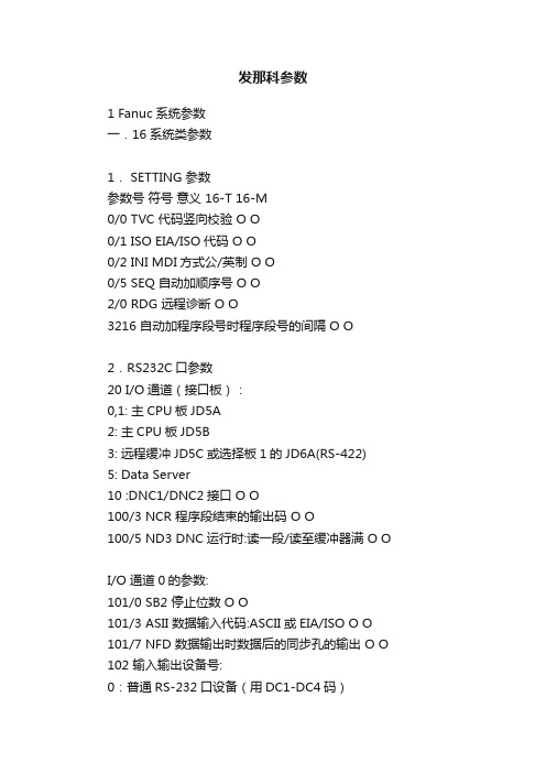
发那科参数1 Fanuc系统参数一.16系统类参数1. SETTING 参数参数号符号意义 16-T 16-M0/0 TVC 代码竖向校验 O O0/1 ISO EIA/ISO代码 O O0/2 INI MDI方式公/英制 O O0/5 SEQ 自动加顺序号 O O2/0 RDG 远程诊断 O O3216 自动加程序段号时程序段号的间隔 O O2.RS232C口参数20 I/O通道(接口板):0,1: 主CPU板JD5A2: 主CPU板JD5B3: 远程缓冲JD5C或选择板1的JD6A(RS-422) 5: Data Server10 :DNC1/DNC2接口 O O100/3 NCR 程序段结束的输出码 O O100/5 ND3 DNC运行时:读一段/读至缓冲器满 O OI/O 通道0的参数:101/0 SB2 停止位数 O O101/3 ASII 数据输入代码:ASCII或EIA/ISO O O 101/7 NFD 数据输出时数据后的同步孔的输出 O O 102 输入输出设备号:0:普通RS-232口设备(用DC1-DC4码)3:Handy File(3〃软盘驱动器) O O103 波特率:10:480011:960012:19200 O OI/O 通道1的参数:111/0 SB2 停止位数 O O111/3 ASI 数据输入代码:ASCII或EIA/ISO O O111/7 NFD 数据输出时数据后的同步孔的输出 O O 112 输入输出设备号:0:普通RS-232口设备(用DC1-DC4码)3:Handy File(3〃软盘驱动器) O O113 波特率:10:480011:960012:19200 O O其它通道参数请见参数说明书。
3.进给伺服控制参数1001/0 INM 公/英制丝杠 O O1002/2 SFD 是否移动参考点 O O1002/3 AZR 未回参考点时是否报警(#90号) O 1006/0,1 ROT,ROS 设定回转轴和回转方式 O O 1006/3 DIA 指定直径/半径值编程 O1006/5 ZMI 回参考点方向 O O1007/3 RAA 回转轴的转向(与1008/1:RAB合用) O O 1008/0 ROA 回转轴的循环功能 O O1008/1 RAB 绝对回转指令时,是否近距回转 O O 1008/2 RRL 相对回转指令时是否规算 O O1260 回转轴一转的回转量 O O1010 CNC的控制轴数(不包括PMC轴) O O1020 各轴的编程轴名 O O1022 基本坐标系的轴指定 O O1023 各轴的伺服轴号 O O1410 空运行速度 O O1420 快速移动(G00)速度 O O1421 快速移动倍率的低速(Fo) O O1422 最高进给速度允许值(所有轴一样) O O 1423 最高进给速度允许值(各轴分别设) O O 1424 手动快速移动速度 O O1425 回参考点的慢速 FL O O1620 快速移动G00时直线加减速时间常数 O O 1622 切削进给时指数加减速时间常数 O O 1624 JOG方式的指数加减速时间常数 O O 1626 螺纹切削时的加减速时间常数 O1815/1 OPT 用分离型编码器 O O1815/5 APC 用绝对位置编码器 O O1816/4,5,6 DM1--3 检测倍乘比DMR O O 1820 指令倍乘比CMR O O1819/0 FUP 位置跟踪功能生效 O O1825 位置环伺服增益 O O1826 到位宽度 O O1828 运动时的允许位置误差 O O1829 停止时的允许位置误差 O O1850 参考点的栅格偏移量 O O1851 反向间隙补偿量 O O1852 快速移动时的反向间隙补偿量 O O1800/4 RBK 进给/快移时反向间补量分开 O O 4.坐标系参数1201/0 ZPR 手动回零点后自动设定工件坐标系 O O1250 自动设定工件坐标系的坐标值 O O1201/2 ZCL 手动回零点后是否取消局部坐标系 O O1202/3 RLC 复位时是否取消局部坐标系 O O1240 第一参考点的坐标值 O O1241 第二参考点的坐标值 O O1242 第三参考点的坐标值 O O1243 第四参考点的坐标值 O O5.行程限位参数1300/0 OUT 第二行程限位的禁止区(内/外) O O1320 第一行程限位的正向值 O O1322 第一行程限位的反向值 O O1323 第二行程限位的正向值 O O1324 第二行程限位的反向值 O O1325 第三行程限位的正向值 O O1321 第三行程限位的反向值 O O6.DI/DO参数3003/0 ITL 互锁信号的生效 O O3003/2 ITX 各轴互锁信号的生效 O O3003/3 DIT 各轴各方向互锁信号的生效 O O作者: wqm8181 2006-12-14 19:51 回复此发言--------------------------------------------------------------------------------2 Fanuc系统参数3004/5 OTH 超程限位信号的检测 O O3010 MF,SF,TF,BF滞后的时间 O O3011 FIN宽度 O O3017 RST信号的输出时间 O O3030 M代码位数 O O3031 S 代码位数 O O3032 T代码位数 O O3033 B代码位数 O O7.显示和编辑3102/3 CHI 汉字显示 O O3104/3 PPD 自动设坐标系时相对坐标系清零 O O 3104/4 DRL 相对位置显示是否包括刀长补偿量 O O 3104/5 DRC 相对位置显示是否包括刀径补偿量 O O 3104/6 DRC 绝对位置显示是否包括刀长补偿量 O O 3104/7 DAC 绝对位置显示是否包括刀径补偿量 O O 3105/0 DPF 显示实际进给速度 O O3105/ DPS 显示实际主轴速度和T代码 O O3106/4 OPH 显示操作履历 O O3106/5 SOV 显示主轴倍率值 O O3106/7 OHS 操作履历采样 O O3107/4 SOR 程序目录按程序序号显示 O O3107/5 DMN 显示G代码菜单 O O3109/1 DWT 几何/磨损补偿显示G/W O O3111/0 SVS 显示伺服设定画面 O O3111/1 SPS 显示主轴调整画面 O O3111/5 OPM 显示操作监控画面 O O3111/6 OPS 操作监控画面显示主轴和电机的速度 O O3111/7 NPA 报警时转到报警画面 O O3112/0 SGD 波形诊断显示生效(程序图形显示无效) O O 3112/5 OPH 操作履历记录生效 O O3122 操作履历画面上的时间间隔 O O3203/7 MCL MDI方式编辑的程序是否能保留 O O3290/0 WOF 用MDI键输入刀偏量 O O3290/2 MCV 用MDI键输入宏程序变量 O O3290/3 WZO 用MDI键输入工件零点偏移量 O O3290/4 IWZ 用MDI键输入工件零点偏移量(自动方式) O 3290/7 KEY 程序和数据的保护键 O O8.编程参数3202/0 NE8 O8000—8999程序的保护 O O3202/4 NE9 O9000—9999程序的保护 O O3401/0 DPI 小数点的含义 O O3401/4 MAB MDI方式G90/G91的切换 O3401/5 ABS MDI方式用该参数切换G90/G91 O9.螺距误差补偿3620 各轴参考点的补偿号 O O3621 负方向的最小补偿点号 O O3622 正方向的最大补偿点号 O O3623 螺补量比率 O O3624 螺补间隔 O O10.刀具补偿3109/1 DWT G,W分开 O O3290/0 WOF MDI设磨损值 O O3290/1 GOF MDI设几何值 O O5001/0 TCL 刀长补偿A,B,C O5001/1 TLB 刀长补偿轴 O5001/2 OFH 补偿号地址D,H O5001/5 TPH G45-G48的补偿号地址D,H O5002/0 LD1 刀补值为刀号的哪位数 O5002/1 LGN 几何补偿的补偿号 O5002/5 LGC 几何补偿的删除 O5002/7 WNP 刀尖半径补偿号的指定 O5003/6 LVC/LVK 复位时删除刀偏量 O O5003/7 TGC 复位时删除几何补偿量(#5003/6=1) O 5004/1 ORC 刀偏值半径/直径指定 O5005/2 PRC 直接输入刀补值用PRC信号 O5006/0 OIM 公/英制单位转换时自动转换刀补值 O O 5013 最大的磨损补偿值 O5014 最大的磨损补偿增量值 O11.主轴参数3701/1 ISI 使用串行主轴 O O3701/4 SS2 用第二串行主轴 O O3705/0 ESF S和SF的输出 O O3705/1 GST SOR信号用于换挡/定向 O3705/2 SGB 换挡方法A,B O3705/4 EVS S和SF的输出 O3706/4 GTT 主轴速度挡数(T/M型) O3706/6,7 CWM/TCW M03/M04的极性 O O3708/0 SAR 检查主轴速度到达信号 O O3708/1 SAT 螺纹切削开始检查SAR O3730 主轴模拟输出的增益调整 O O3731 主轴模拟输出时电压偏移的补偿 O O3732 定向/换挡的主轴速度 O O3735 主轴电机的允许最低速度 O3736 主轴电机的允许最低速度 O3740 检查SAR的延时时间 O O3741 第一挡主轴最高速度 O O3742 第二挡主轴最高速度 O O3743 第三挡主轴最高速度 O O3744 第四挡主轴最高速度 O3751 第一至第二挡的切换速度 O3752 第二至第三挡的切换速度 O3771 G96的最低主轴速度 O O3772 最高主轴速度 O O4019/7 主轴电机初始化 O O作者: wqm8181 2006-12-14 19:51 回复此发言--------------------------------------------------------------------------------3 Fanuc系统参数4133 主轴电机代码 O O12.其它6510 图形显示的绘图坐标系 O7110 手摇脉冲发生器的个数 O O7113 手脉的倍比m O O7114 手脉的倍比n O O13.0i系统的有关参数8130 总控制轴数 O O8131/0 HPG 使用手摇脉冲发生器 O O8132/0 TLF 刀具寿命管理功能 O O8132/3 ISC 用分度工作台 O8133/0 SSC G96功能生效 O O8134/0 IAP 图形功能生效 O O二.0系统参数1.SETTING 参数参数号符号意义 0-T 0-M0000 PWE 参数写入 O O0000 TVON 代码竖向校验 O O0000 ISO EIA/ISO代码 O O0000 INCH MDI方式公/英制 O O0000 I/O RS-232C口 O O0000 SEQ 自动加顺序号 O O2.RS232C口参数2/0 STP2 通道0停止位 OO552 通道0波特率 O O12/0 STP2 通道1停止位 O O553 通道1波特率 O O50/0 STP2 通道2停止位 O O250 通道2波特率 O O51/0 STP2 通道3停止位 O O251 通道3 波特率 O O55/3 RS42 Remote Buffer 口RS232/422 O O390/7 NODC3 缓冲区满 O O3.伺服控制轴参数1/0 SCW 公/英制丝杠 O O3/0.1.2.4 ZM 回零方向 O O8/2.3.4 ADW 轴名称 O30/0.4 ADW 轴名称 O32/2.3 LIN 3,4轴,回转轴/直线轴 O388/1 ROAX 回转轴循环功能 O388/2 RODRC 绝对指令近距离回转 O388/3 ROCNT 相对指令规算 O788 回转轴每转回转角度 O11/2 ADLN 第4轴,回转轴/直线轴 O398/1 ROAX 回转轴循环功能 O398/2 RODRC 绝对指令近距离回转 O398/3 ROCNT 相对指令规算 O788 回转轴每转回转角度 O860 回转轴每转回转角度 O500-503 INPX,Y,Z,4 到位宽度 O O504-507 SERRX,Y,Z,4 运动时误差极限 O O 508-511 GRDSX.Y,Z,4 栅格偏移量 O O512-515 LPGIN 位置伺服增益 O O517 LPGIN 位置伺服增益(各轴增益) O O518-521 RPDFX,Y,X,4 G00速度 O O522-525 LINTX,Y,Z,4 直线加/减速时间常数 O O 526 THRDT G92时间常数 O528 THDFL G92X轴的最低速度 O527 FEDMX F的极限值 O O529 FEEDT F的时间常数 O O530 FEDFL 指数函数加减速时间常数 O O533 RPDFL 手动快速移动倍率的最低值 O O534 ZRNFL 回零点的低速 O O535-538 BKLX,Y,Z,4 反向间隙 O O593-596 STPEX,Y,Z,4 伺服轴停止时的位置误差极限 O O 393/5 快速倍率为零时机床移动 O O4.坐标系参数10/7 APRS 回零点后自动设定工件坐标系 O O2/1 PPD 自动设坐标系相对坐标值清零 O24/6 CLCL 手动回零后清除局部坐标系 O28/5 EX10D 坐标系外部偏移时刀偏量的值(×10) O 708-711 自动设定工件坐标系的坐标值 O735-738 第二参考点 O O780-783 第三参考点 O O784-787 第四参考点 O O5.行程限位8/6 OTZN Z轴行程限位检查否 O15/4 LM2 第二行程限位 O24/4 INOUT 第三行程限位 O57/5 HOT3 硬超程-LMX--+LMZ有效 O65/3 PSOT 回零点前是否检查行程限位 O O700-703 各轴正向行程 O O704-707 各轴反向行程 O O15/2 COTZ 硬超程-LMX--+LMZ有效 O20/4 LM2 第二行程限位 O24/4 INOUT 第三行程限位 O743-746 第二行程正向限位 O747-750 第二行程反向限位 O804-806 第三行程正向限位 O807-809 第三行程反向限位 O770-773 第二行程正向限位 O774-777 第二行程反向限位 O747-750 第三行程正向限位 O751-754 第三行程反向限位 O760-763 第四行程正向限位 O764-767 第四行程反向限位 O6.进给与伺服电机参数1/6 RDRN 空运行时,快速移动指令是否有效 O O 8/5 ROVE 快速倍率信号ROV2(G117/7)有效 O 49/6 NPRV 不用位置编码器实现主轴每转进给 O O 20/5 NCIPS 是否进行到位检查 O O4—7 参考计数器容量 O O4—7 检测倍比 O O21/0.1.2.3 APC 绝对位置编码器 O O4 Fanuc系统参数35/7 ACMR 任意CMR O O37/0.1.2.3 SPTP 用分离型编码器 O O100-103 指令倍比CMR O O7.DI/DO参数8/7 EILK Z轴/各轴互锁 O O9/0.1.2.3 TFIN FIN信号时间 O O9/4.5.6.7 TMF M,S,T读信号时间 O O12/1 ZILK Z轴/所有轴互锁 O31/5 ADDCF GR1,GR2,DRN 地址 O252 复位信号扩展时间 O O8.显示和编辑1/1 PROD 相对坐标显示是否包括刀补量 O O2/1 PPD 自动设坐标系相对坐标清零 O O15/1 NWCH 刀具磨损补偿显示W O O18/5 PROAD 绝对坐标系显示是否包括刀补量 O 23/3 CHI 汉字显示 O O28/2 DACTF 显示实际速度 O O29/0.1 DSP 第3,4轴位置显示 O35/3 NDSP 第4轴位置显示 O38/3 FLKY 用全键盘 O O48/7 SFFDSP 显示软按键 O O60/0 DADRDP 诊断画面上显示地址字 O O60/2 LDDSPG 显示梯形图 O O60/5 显示操作监控画面 O O64/0 SETREL 自动设坐标系时相对坐标清零 O O 77/2 伺服波形显示 O O389/0 SRVSET 显示伺服设定画面 O O389/1 WKNMDI 显示主轴调整画面 O O9.编程参数10/4 PRG9 O9000-O9999号程序保护 O O15/7 CPRD 小数点的含义 O O28/4 EXTS 外部程序号检索 O O29/5 MABS MDI-B中,指令取决于G90/G91设定 O 389/2 PRG8 O8000-O8999号程序保护 O O394/6 WKZRST 自动设工件坐标系时设为G54 O10.螺距误差补偿11/0.1 PML 螺补倍率 O O712-715 螺补间隔 O756-759 螺补间隔 O1000, 20003000, 4000 补偿基准点 O O1001-11282001-21283001-31284001-4128 补偿值 O O11.刀具补偿1/3 TOC 复位时清除刀长补偿矢量 0 O1/4 ORC 刀具补偿值(半径/直径输入) O8/6 NOFC 刀补量计数器输入 O10/5 DOFSI 刀偏量直接输入 O13/1 GOFU2 几何补偿号(由刀补号或刀号)指定 O13/2 GMOFS 加几何补偿值(运动/变坐标) 014/0 T2D T代码位数 O14/1 GMCL 复位时是否清几何补偿值 O14/5 WIGA 刀补量的限制 O15/4 MORB 直接输入刀补测量值的按钮 O24/6 QNI 刀补测量B时补偿号的选择 O75/3 WNPT 刀尖补偿号的指定(在几何还是在磨损中) O122 刀补测量B时的补偿号 O728 最大的刀具磨损补偿增量值 O729 最大的刀具磨损补偿值 O78/0 NOINOW 用MDI键输入磨损补偿量 O O78/1 NOINOG 用MDI键输入几何补偿量 O O78/2 NOINMV 用MDI键输入宏程序变量 O O78/3 NOINMZ 用MDI键输入工件坐标偏移量 O O393/2 MKNMDI 在自动方式的停止时,用MDI键输入工件坐标偏移量 O O12.主轴参数13/5 ORCM 定向时,S模拟输出的极性13/6.7 TCW,CWM S模拟M03,M04的方向 O O 14/2 主轴转速显示 O O24/2 SCTO 是否检查SAR(G120/4) O O49/0 EVSF SF的输出 O O71/0 ISRLPC 串行主轴时编码器信号的接法 O71/4 SRL2SP 用1或2个串行主轴 O71/7 FSRSP 是否用串行主轴 O108 G96或换挡(#3/5:GST=1)或模拟主轴定向SOR:G120/5:M)=1速度 OO110 检查SAR(G120/4)的延时时间 O516 模拟主轴的增益(G96) O539 模拟主轴电机的偏移补偿电压(G96) O551 G96的主轴最的转速 O556 G96的主轴最高转速 O540-543 各挡主轴的最高转速 O3/5 GST 用SOR(G120/5)定向/换挡 O14/0 SCTA 加工启动时检查SAR信号 O20/7 SFOUT 换挡时输出SF O29/4 FSOB G96时输出SF O35/6 LGCM 各挡最高速的参数号 O539,541,555 各挡的主轴最高转速 O542 主轴最高转速 O543 主轴最低转速 O585,586 主轴换挡速度(B型) O577 模拟主轴电机的偏移补偿电压 O6519/7 主轴电机初始化 O O6633 主轴电机代码 O O6501/2 POSC2 用位置编码器 O O6501/5-7 CAXIS1-3 用高分辨率编码器 O O 6503/0 PCMGSL 定向方法(编码器/磁传感器) O O 6501/1 PCCNCT 内装传感器 O O6501/4.6.7 位置编码器信号 O O6504/1 HRPC 高分辨率编码器 O O13.其它24/0 IGNPMC 用PMC O O71/6 DPCRAM 显示PMC操作菜单 O O123 图形显示的绘图坐标系 O。
发那科参数
7.显示和编辑
3102/3 CHI 汉字显示 O O
3104/3 PPD 自动设坐标系时相对坐标系清零 O O
3104/4 DRL 相对位置显示是否包括刀长补偿量 O O
3104/5 DRC 相对位置显示是否包括刀径补偿量 O O
3104/6 DRC 绝对位置显示是否包括刀长补偿量 O O
8132/0 TLF 刀具寿命管理功能 O O
8132/3 ISC 用分度工作台 O
8133/0 SSC G96功能生效 O O
8134/0 IAP 图形功能生效 O O
3741 第一挡主轴最高速度 O O
3742 第二挡主轴最高速度 O O
3743 第三挡主轴最高速度 O O
3744 第四挡主轴最高速度 O
3751 第一至第二挡的切换速度 O
3752 第二至第三挡的切换速度 O
3771 G96的最低主轴速度 O O
3772 最高主轴速度 O O
1829 停止时的允许位置误差 O O
1850 参考点的栅格偏移量 O O
1851 反向间隙补偿量 O O
1852 快速移动时的反向间隙补偿量 O O
1800/4 RBK 进给/快移时反向间补量分开 O O
4.坐标系参数
1201/0 ZPR 手动回零点后自动设定工件坐标系 O O
3705/1 GST SOR信号用于换挡/定向 O
3705/2 SGB 换挡方法A,B O
3705/4 EVS S和SF的输出 O
3706/4 GTT 主轴速度挡数(T/M型) O
3706/6,7 CWM/TCW M03/M04的极性 O O
Fanuc常用系统全参数

1 Fanuc系统参数一.16系统类参数1.SETTING 参数参数号符号意义16-T 16-M0/0 TVC 代码竖向校验O O0/1 ISO EIA/ISO代码O O0/2 INI MDI方式公/英制O O0/5 SEQ 自动加顺序号O O2/0 RDG 远程诊断O O3216 自动加程序段号时程序段号的间隔O O2.RS232C口参数20 I/O通道(接口板):0,1: 主CPU板JD5A2: 主CPU板JD5B3: 远程缓冲JD5C或选择板1的JD6A(RS-422)5: Data Server10 :DNC1/DNC2接口O O100/3 NCR 程序段结束的输出码O O100/5 ND3 DNC运行时:读一段/读至缓冲器满O OI/O 通道0的参数:101/0 SB2 停止位数O O101/3 ASII 数据输入代码:ASCII或EIA/ISO O O 101/7 NFD 数据输出时数据后的同步孔的输出O O 102 输入输出设备号:0:普通RS-232口设备(用DC1-DC4码)3:Handy File(3〃软盘驱动器)O O103 波特率:10:480011:960012:19200 O OI/O 通道1的参数:111/0 SB2 停止位数O O111/3 ASI 数据输入代码:ASCII或EIA/ISO O O 111/7 NFD 数据输出时数据后的同步孔的输出O O 112 输入输出设备号:0:普通RS-232口设备(用DC1-DC4码)3:Handy File(3〃软盘驱动器)O O113 波特率:10:480011:960012:19200 O O其它通道参数请见参数说明书。
3.进给伺服控制参数1001/0 INM 公/英制丝杠O O1002/2 SFD 是否移动参考点O O1002/3 AZR 未回参考点时是否报警(#90号)O 1006/0,1 ROT,ROS 设定回转轴和回转方式O O 1006/3 DIA 指定直径/半径值编程O1006/5 ZMI 回参考点方向O O1007/3 RAA 回转轴的转向(与1008/1:RAB合用) O O 1008/0 ROA 回转轴的循环功能O O1008/1 RAB 绝对回转指令时,是否近距回转O O 1008/2 RRL 相对回转指令时是否规算O O1260 回转轴一转的回转量O O1010 CNC的控制轴数(不包括PMC轴) O O1020 各轴的编程轴名O O1022 基本坐标系的轴指定O O1023 各轴的伺服轴号O O1410 空运行速度O O1420 快速移动(G00)速度O O1421 快速移动倍率的低速(Fo) O O1422 最高进给速度允许值(所有轴一样) O O1423 最高进给速度允许值(各轴分别设) O O1424 手动快速移动速度O O1425 回参考点的慢速FL O O1620 快速移动G00时直线加减速时间常数O O1622 切削进给时指数加减速时间常数O O1624 JOG方式的指数加减速时间常数O O1626 螺纹切削时的加减速时间常数O1815/1 OPT 用分离型编码器O O1815/5 APC 用绝对位置编码器O O1816/4,5,6 DM1--3 检测倍乘比DMR O O1820 指令倍乘比CMR O O1819/0 FUP 位置跟踪功能生效O O1825 位置环伺服增益O O1826 到位宽度O O1828 运动时的允许位置误差O O1829 停止时的允许位置误差O O1850 参考点的栅格偏移量O O1851 反向间隙补偿量O O1852 快速移动时的反向间隙补偿量O O1800/4 RBK 进给/快移时反向间补量分开O O4.坐标系参数1201/0 ZPR 手动回零点后自动设定工件坐标系O O1250 自动设定工件坐标系的坐标值O O1201/2 ZCL 手动回零点后是否取消局部坐标系O O1202/3 RLC 复位时是否取消局部坐标系O O1240 第一参考点的坐标值O O1241 第二参考点的坐标值O O1242 第三参考点的坐标值O O1243 第四参考点的坐标值O O5.行程限位参数1300/0 OUT 第二行程限位的禁止区(内/外)O O1320 第一行程限位的正向值O O1322 第一行程限位的反向值O O1323 第二行程限位的正向值O O1324 第二行程限位的反向值O O1325 第三行程限位的正向值O O1321 第三行程限位的反向值O O6.DI/DO参数3003/0 ITL 互锁信号的生效O O3003/2 ITX 各轴互锁信号的生效O O3003/3 DIT 各轴各方向互锁信号的生效O O作者:wqm8181 2006-12-14 19:51 回复此发言--------------------------------------------------------------------------------2 Fanuc系统参数3004/5 OTH 超程限位信号的检测O O3010 MF,SF,TF,BF滞后的时间O O3011 FIN宽度O O3017 RST信号的输出时间O O3030 M代码位数O O3031 S 代码位数O O3032 T代码位数O O3033 B代码位数O O7.显示和编辑3102/3 CHI 汉字显示O O3104/3 PPD 自动设坐标系时相对坐标系清零O O3104/4 DRL 相对位置显示是否包括刀长补偿量O O3104/5 DRC 相对位置显示是否包括刀径补偿量O O3104/6 DRC 绝对位置显示是否包括刀长补偿量O O3104/7 DAC 绝对位置显示是否包括刀径补偿量O O3105/0 DPF 显示实际进给速度O O3105/ DPS 显示实际主轴速度和T代码O O3106/4 OPH 显示操作履历O O3106/5 SOV 显示主轴倍率值O O3106/7 OHS 操作履历采样O O3107/4 SOR 程序目录按程序序号显示O O3107/5 DMN 显示G代码菜单O O3109/1 DWT 几何/磨损补偿显示G/W O O3111/0 SVS 显示伺服设定画面O O3111/1 SPS 显示主轴调整画面O O3111/5 OPM 显示操作监控画面O O3111/6 OPS 操作监控画面显示主轴和电机的速度O O 3111/7 NPA 报警时转到报警画面O O3112/0 SGD 波形诊断显示生效(程序图形显示无效)O O 3112/5 OPH 操作履历记录生效O O3122 操作履历画面上的时间间隔O O3203/7 MCL MDI方式编辑的程序是否能保留O O3290/0 WOF 用MDI键输入刀偏量O O3290/2 MCV 用MDI键输入宏程序变量O O3290/3 WZO 用MDI键输入工件零点偏移量O O3290/4 IWZ 用MDI键输入工件零点偏移量(自动方式) O 3290/7 KEY 程序和数据的保护键O O8.编程参数3202/0 NE8 O8000—8999程序的保护O O3202/4 NE9 O9000—9999程序的保护O O3401/0 DPI 小数点的含义O O3401/4 MAB MDI方式G90/G91的切换O3401/5 ABS MDI方式用该参数切换G90/G91 O9.螺距误差补偿3620 各轴参考点的补偿号O O3621 负方向的最小补偿点号O O3622 正方向的最大补偿点号O O3623 螺补量比率O O3624 螺补间隔O O10.刀具补偿3109/1 DWT G,W分开O O3290/0 WOF MDI设磨损值O O3290/1 GOF MDI设几何值O O5001/0 TCL 刀长补偿A,B,C O5001/1 TLB 刀长补偿轴O5001/2 OFH 补偿号地址D,H O5001/5 TPH G45-G48的补偿号地址D,H O5002/0 LD1 刀补值为刀号的哪位数O5002/1 LGN 几何补偿的补偿号O5002/5 LGC 几何补偿的删除O5002/7 WNP 刀尖半径补偿号的指定O5003/6 LVC/LVK 复位时删除刀偏量O O5003/7 TGC 复位时删除几何补偿量(#5003/6=1)O 5004/1 ORC 刀偏值半径/直径指定O5005/2 PRC 直接输入刀补值用PRC信号O5006/0 OIM 公/英制单位转换时自动转换刀补值O O 5013 最大的磨损补偿值O5014 最大的磨损补偿增量值O11.主轴参数3701/1 ISI 使用串行主轴O O3701/4 SS2 用第二串行主轴O O3705/0 ESF S和SF的输出O O3705/1 GST SOR信号用于换挡/定向O3705/2 SGB 换挡方法A,B O3705/4 EVS S和SF的输出O3706/4 GTT 主轴速度挡数(T/M型)O3706/6,7 CWM/TCW M03/M04的极性O O3708/0 SAR 检查主轴速度到达信号O O3708/1 SAT 螺纹切削开始检查SAR O3730 主轴模拟输出的增益调整O O3731 主轴模拟输出时电压偏移的补偿O O3732 定向/换挡的主轴速度O O3735 主轴电机的允许最低速度O3736 主轴电机的允许最低速度O3740 检查SAR的延时时间O O3741 第一挡主轴最高速度O O3742 第二挡主轴最高速度O O3743 第三挡主轴最高速度O O3744 第四挡主轴最高速度O3751 第一至第二挡的切换速度O3752 第二至第三挡的切换速度O3771 G96的最低主轴速度O O3772 最高主轴速度O O4019/7 主轴电机初始化O O作者:wqm8181 2006-12-14 19:51 回复此发言--------------------------------------------------------------------------------3 Fanuc系统参数4133 主轴电机代码O O12.其它6510 图形显示的绘图坐标系O7110 手摇脉冲发生器的个数O O7113 手脉的倍比m O O7114 手脉的倍比n O O13.0i系统的有关参数8130 总控制轴数O O8131/0 HPG 使用手摇脉冲发生器O O8132/0 TLF 刀具寿命管理功能O O8132/3 ISC 用分度工作台O8133/0 SSC G96功能生效O O8134/0 IAP 图形功能生效O O二.0系统参数1.SETTING 参数参数号符号意义0-T 0-M0000 PWE 参数写入O O0000 TVON 代码竖向校验O O0000 ISO EIA/ISO代码O O0000 INCH MDI方式公/英制O O0000 I/O RS-232C口O O0000 SEQ 自动加顺序号O O2.RS232C口参数2/0 STP2 通道0停止位O O552 通道0波特率O O12/0 STP2 通道1停止位O O553 通道1波特率O O50/0 STP2 通道2停止位O O250 通道2波特率O O51/0 STP2 通道3停止位O O251 通道3 波特率O O55/3 RS42 Remote Buffer 口RS232/422 O O390/7 NODC3 缓冲区满O O3.伺服控制轴参数1/0 SCW 公/英制丝杠O O3/0.1.2.4 ZM 回零方向O O8/2.3.4 ADW 轴名称O30/0.4 ADW 轴名称O32/2.3 LIN 3,4轴,回转轴/直线轴O388/1 ROAX 回转轴循环功能O388/2 RODRC 绝对指令近距离回转O388/3 ROCNT 相对指令规算O788 回转轴每转回转角度O11/2 ADLN 第4轴,回转轴/直线轴O398/1 ROAX 回转轴循环功能O398/2 RODRC 绝对指令近距离回转O398/3 ROCNT 相对指令规算O788 回转轴每转回转角度O860 回转轴每转回转角度O500-503 INPX,Y,Z,4 到位宽度O O504-507 SERRX,Y,Z,4 运动时误差极限O O508-511 GRDSX.Y,Z,4 栅格偏移量O O512-515 LPGIN 位置伺服增益O O517 LPGIN 位置伺服增益(各轴增益) O O518-521 RPDFX,Y,X,4 G00速度O O522-525 LINTX,Y,Z,4 直线加/减速时间常数O O526 THRDT G92时间常数O528 THDFL G92X轴的最低速度O527 FEDMX F的极限值O O529 FEEDT F的时间常数O O530 FEDFL 指数函数加减速时间常数O O533 RPDFL 手动快速移动倍率的最低值O O534 ZRNFL 回零点的低速O O535-538 BKLX,Y,Z,4 反向间隙O O593-596 STPEX,Y,Z,4 伺服轴停止时的位置误差极限O O 393/5 快速倍率为零时机床移动O O4.坐标系参数10/7 APRS 回零点后自动设定工件坐标系O O2/1 PPD 自动设坐标系相对坐标值清零O24/6 CLCL 手动回零后清除局部坐标系O28/5 EX10D 坐标系外部偏移时刀偏量的值(×10)O708-711 自动设定工件坐标系的坐标值O735-738 第二参考点O O780-783 第三参考点O O784-787 第四参考点O O5.行程限位8/6 OTZN Z轴行程限位检查否O15/4 LM2 第二行程限位O24/4 INOUT 第三行程限位O57/5 HOT3 硬超程-LMX--+LMZ有效O65/3 PSOT 回零点前是否检查行程限位O O700-703 各轴正向行程O O704-707 各轴反向行程O O15/2 COTZ 硬超程-LMX--+LMZ有效O20/4 LM2 第二行程限位O24/4 INOUT 第三行程限位O743-746 第二行程正向限位O747-750 第二行程反向限位O804-806 第三行程正向限位O807-809 第三行程反向限位O770-773 第二行程正向限位O774-777 第二行程反向限位O747-750 第三行程正向限位O751-754 第三行程反向限位O760-763 第四行程正向限位O764-767 第四行程反向限位O6.进给与伺服电机参数1/6 RDRN 空运行时,快速移动指令是否有效O O 8/5 ROVE 快速倍率信号ROV2(G117/7)有效O49/6 NPRV 不用位置编码器实现主轴每转进给O O 20/5 NCIPS 是否进行到位检查O O4—7 参考计数器容量O O4—7 检测倍比O O21/0.1.2.3 APC 绝对位置编码器O O4 Fanuc系统参数35/7 ACMR 任意CMR O O37/0.1.2.3 SPTP 用分离型编码器O O100-103 指令倍比CMR O O7.DI/DO参数8/7 EILK Z轴/各轴互锁O O9/0.1.2.3 TFIN FIN信号时间O O9/4.5.6.7 TMF M,S,T读信号时间O O12/1 ZILK Z轴/所有轴互锁O31/5 ADDCF GR1,GR2,DRN 地址O252 复位信号扩展时间O O8.显示和编辑1/1 PROD 相对坐标显示是否包括刀补量O O2/1 PPD 自动设坐标系相对坐标清零O O15/1 NWCH 刀具磨损补偿显示W O O18/5 PROAD 绝对坐标系显示是否包括刀补量O 23/3 CHI 汉字显示O O28/2 DACTF 显示实际速度O O29/0.1 DSP 第3,4轴位置显示O35/3 NDSP 第4轴位置显示O38/3 FLKY 用全键盘O O48/7 SFFDSP 显示软按键O O60/0 DADRDP 诊断画面上显示地址字O O60/2 LDDSPG 显示梯形图O O60/5 显示操作监控画面O O64/0 SETREL 自动设坐标系时相对坐标清零O O 77/2 伺服波形显示O O389/0 SRVSET 显示伺服设定画面O O389/1 WKNMDI 显示主轴调整画面O O9.编程参数10/4 PRG9 O9000-O9999号程序保护O O15/7 CPRD 小数点的含义O O28/4 EXTS 外部程序号检索O O29/5 MABS MDI-B中,指令取决于G90/G91设定O 389/2 PRG8 O8000-O8999号程序保护O O394/6 WKZRST 自动设工件坐标系时设为G54 O10.螺距误差补偿11/0.1 PML 螺补倍率O O712-715 螺补间隔O756-759 螺补间隔O1000, 20003000, 4000 补偿基准点O O1001-11282001-21283001-31284001-4128 补偿值O O11.刀具补偿1/3 TOC 复位时清除刀长补偿矢量0 O1/4 ORC 刀具补偿值(半径/直径输入) O8/6 NOFC 刀补量计数器输入O10/5 DOFSI 刀偏量直接输入O13/1 GOFU2 几何补偿号(由刀补号或刀号)指定O13/2 GMOFS 加几何补偿值(运动/变坐标)014/0 T2D T代码位数O14/1 GMCL 复位时是否清几何补偿值O14/5 WIGA 刀补量的限制O15/4 MORB 直接输入刀补测量值的按钮O24/6 QNI 刀补测量B时补偿号的选择O75/3 WNPT 刀尖补偿号的指定(在几何还是在磨损中) O122 刀补测量B时的补偿号O728 最大的刀具磨损补偿增量值O729 最大的刀具磨损补偿值O78/0 NOINOW 用MDI键输入磨损补偿量O O78/1 NOINOG 用MDI键输入几何补偿量O O78/2 NOINMV 用MDI键输入宏程序变量O O78/3 NOINMZ 用MDI键输入工件坐标偏移量O O393/2 MKNMDI 在自动方式的停止时,用MDI键输入工件坐标偏移量O O12.主轴参数13/5 ORCM 定向时,S模拟输出的极性13/6.7 TCW,CWM S模拟M03,M04的方向O O14/2 主轴转速显示O O24/2 SCTO 是否检查SAR(G120/4) O O49/0 EVSF SF的输出O O71/0 ISRLPC 串行主轴时编码器信号的接法O71/4 SRL2SP 用1或2个串行主轴O71/7 FSRSP 是否用串行主轴O108 G96或换挡(#3/5:GST=1)或模拟主轴定向SOR:G120/5:M)=1速度OO110 检查SAR(G120/4)的延时时间O516 模拟主轴的增益(G96) O539 模拟主轴电机的偏移补偿电压(G96) O551 G96的主轴最的转速O556 G96的主轴最高转速O540-543 各挡主轴的最高转速O3/5 GST 用SOR(G120/5)定向/换挡O14/0 SCTA 加工启动时检查SAR信号O20/7 SFOUT 换挡时输出SF O29/4 FSOB G96时输出SF O35/6 LGCM 各挡最高速的参数号O539,541,555 各挡的主轴最高转速O542 主轴最高转速O实用标准文案543 主轴最低转速O585,586 主轴换挡速度(B型) O577 模拟主轴电机的偏移补偿电压O6519/7 主轴电机初始化O O6633 主轴电机代码O O6501/2 POSC2 用位置编码器O O6501/5-7 CAXIS1-3 用高分辨率编码器O O 6503/0 PCMGSL 定向方法(编码器/磁传感器) O O 6501/1 PCCNCT 内装传感器O O6501/4.6.7 位置编码器信号O O6504/1 HRPC 高分辨率编码器O O13.其它24/0 IGNPMC 用PMC O O71/6 DPCRAM 显示PMC操作菜单O O123 图形显示的绘图坐标系O文档。
- 1、下载文档前请自行甄别文档内容的完整性,平台不提供额外的编辑、内容补充、找答案等附加服务。
- 2、"仅部分预览"的文档,不可在线预览部分如存在完整性等问题,可反馈申请退款(可完整预览的文档不适用该条件!)。
- 3、如文档侵犯您的权益,请联系客服反馈,我们会尽快为您处理(人工客服工作时间:9:00-18:30)。
EFFECT OF NATURAL VENTILATION AND WIND DIRECTION ON THE THERMALPERFORMANCE OF A BUILDING CEILINGAbdel Aziz Ali AliShoubra Faculty of Engineering Banha University, EgyptGuirguis Nabil Miladhousing & Building Research CenterCairo, EgyptHassan Mahmoud AlyHousing & Building Research Center, Cairo, Egyptp.o.box:1770-cairo waghassan@ABSTRACTNatural ventilation is rapidly becoming a significant part in the design strategy of buildings in situations where electricity is scare or non-existent and saving energy becomes highly important. The aim of present work is to reduce the ceiling temperature by natural ventilation through different opening locations (one window in the front façade and the other window in the rear wall) with sill height ratios of 0.27, 0.36, 0.45, 0.54, and 0.63. Wind tunnel and smoke tunnel were used to investigate the effect of opening locations on the temperature and heat transfer coefficient of a ceiling of a naturally-ventilated room. Here, the ANSYS CFD software was used to determine the flow characteristics in the ventilated room with different opening locations and wind direction. Better flow pattern and heat transfer from the heated ceiling are observed when the front and rear openings are located nearest to the ceiling and center, respectively. An experimental correlation was obtained to predict the influence of sill opening height ratio of front and rear walls on the average heat transfer coefficient ratio of ceiling (/)av o h h where ()o h is the heat transfer coefficient in case of no wind.1. INTRODUCTIONIn previous years, natural ventilation has gained momentum as a suitable passive design strategy for buildings. Design guidance for buildings has been published by BRE [1], CIBSE [2], and BRESCU [3]. Many research works have been done in the field of thermal comfort by natural ventilation in buildings such as Vincent et al. [4] studied the effect of central courtyard on the natural ventilation in refurbished historic buildings, using wind tunnel modeling and computational fluid dynamic. Potangarana [6] developed a design tool based on the boundary layer wind tunnel testing and computational fluids dynamic studies. Results suggested that, although natural ventilation has traditionally been used for low rise buildings. Hassan et al. [9] studied experimentally and numerically the combined effects of the air flow (speed and direction) and window size on thermal comfort in buildings. Tine S. L., et al. [11] studied single sided natural ventilation using a full-scale wind tunnel. The effect of wind velocity, direction and temperature difference on the air flow through the openings was discussed. Fernando M. and Jorge G., [13] estimated the natural ventilation flow rates through buildings. In the present study an experimental and computational investigation were carried out to study the flow2 SOLAR BUILDINGS437characteristics and thermal behavior of air in a ventilated room model with different opening locations.2. EXPERIMENTAL AND CFD WORKAn experimental measurements and numerical comput- ations (using ANSYS 2001) were conducted to evaluate the air flow characteristics inside a building model with different opening locations using a wind tunnel test facility which was designed, built and tested at the Housing & and Building National Research Center by Guirguis et al. [15]. Various scaled-up test models with different opening locations were subjected to wind tunnel tests. The test models (Fig. 1(a)) were in the form of rectangular blocks of dimension 0.22 x 0.22 x 0.235 m and were fabricated from a plastic sheet of 0.003 m thickness (Plexiglas). The front and rear opposite walls have rectangular openings (0.16 m x 0.02 m) and sill height ratios of the front (y front/H) and rear (y r/H) measured from floor was varied as 0.27, 0.36, 0.45, 0.54, and 0.63 where H is the ceiling height. The ceiling was provided with a heating plate at a constant heat flux (410 W/m2). Twenty five thermocouples were used to measure the local ceiling temperature as shown in Fig. 1(b) and two thermocouples to measure the entering air temperature as well as inside the test model. The opening locations can be used to control the inside air temperature.3. COMPUTATIONAL WORKThe nature of the air flow inside buildings is very complex, especially in the downstream region directly behind windows. The air distribution through a ventilated space can be computed from the CFD ANSYS program and are shown in the form of velocity vectors and contours. The CFD numerical results provide more comprehensive data than could be gathered in the experimental work.4. RESULTS AND DISCUSION4.1 Experimental ResultsCross ventilation of some spaces is usually needed to allow natural ventilation to take place at night time with the(a) (b) Fig. 1: The test model.Proceedings of ISES Solar World Congress 2007: Solar Energy and Human Settlement438intention of removing heat gains accumulating throughceiling and exposed walls during day time. Inlet and outlet openings allow air to flow past the ceiling surface to set up a suitable convective circulation. Figures 2 and 3 show the effect of the front and rear opening locations on the normalized average ceiling temperature ()/av a a T T T − and average heat transfer coefficient, (h av / h o ) respectively, where ()o h is evaluated when all openings are closed (No-wind). Ventilation from inlet opening (y front /H = 0.63) to outlet opening (y rear /H = 0.45) appears to reduce ceiling temperature to a minimum normalized value of 0.22 and raises the heat transfer coefficient of the ceiling to normalized value of about 9.4. This would increase air circulation and hence improve cooling effect. It may be observed that the ventilation with case (y front /H = 0.63 and y rear/H = 0.45) is to achieve a higher air change rate past theFig. 2: Normalized average temperature variations ofceiling for different openings locations.Fig. 3: Variations of average heat transfer coefficient ratiofor different openings locations.ceiling than with case (y front /H = 0.63 and y rear /H = 0.63) of cross ventilation. When the front opening locations move to the ceiling, a more significant increasing of (/)av o h h is observed from (3.1 – 4.1), (3.0 – 4.2), (4.6 – 5.4), and (6.9 – 9.5), when the rear opening ratios are maintained at 0.54, 0.63, 0.36, 0.27, and 0.45, respectively. Figures 4 and 5 show the effect of wind direction on the normalized average ceiling temperature and normalized heat transfer coefficient, respectively for opening locations (y front /H=0.63) and (y rear /H =0.45). The average heat transfer coefficient was normalized by the average heat transfer coefficient at angle of attack 90o 90()o h . It is noticed that the normalized average heat transfer coefficient decreases rapidly from wind direction zero degree (normal to building facade) to 15o . As wind direction increases from 15o to 75o nosignificant variation in 90(/)o av h h isobserved.Fig. 4: Normalized average temperature variations ofceiling for building model with different winddirections case (F5R3).Fig. 5: Variations of average heat transfer coefficient ratiofor building model with different wind directions case (F5R3).2 SOLAR BUILDINGS439The experimental correlation of the average heat transfercoefficient ratio (/)av o h h is developed in terms of sill opening height ratios of the front and the rear with a maximum relative error of 10 %.0.1960.6853.41..front av rear oy h y h H H −⎛⎞⎛⎞⎛⎞=⎜⎟⎜⎟⎜⎟⎝⎠⎝⎠⎝⎠ (1)4.2 Computational ResultsThe effect of opening locations on the air movement (velocity distributions) in 3-D geometrically similar ventilated rooms is illustrated in Figure 6 for different values of front sill opening height ratio (0.63, 0.54, 0.45, 0.36, and 0.27). With front opening sill height at 0.63 (group 5), the jet with a maximum velocity attaches to the ceiling by the effect of flow circulation when the rear opening location maintained at 0.45 and better ventilation is occurred specially at upper region of the model. As a result the air movement adjacent to the ceiling is improved and hence this situation allows a good amount of air to remove the heat convected from the ceiling to the inside air that was rejected through the rear opening. When front opening moves toward floor, the rear opening acting on the cool air jet and causes the jet to deflect downwards into the occupied zone where the ventilation inside the model at upper region of the model is attenuated and a wake region formation is appeared.5. CONCLUSIONSThe present numerical results give qualitatively a good discussion of the experimental results of heat transfer. When the front opening locations move toward the ceiling, a more significant increasing of (/)av o h h is observed from (3.1 - 4.1), (3.0 - 4.2), (4.6 - 5.4), and (6.9 – 9.5), with rear sill height opening ratios are maintained at 0.54, 0.63, 0.36, 0.27, and 0.45, respectively. Also, the highest air velocities were occurred close to the ceiling at yfront/H = 0.63 and yrear/H = 0.45 (F5R3) and the highest value of (/)av o h h is found. The normalized heat transfer coefficient at zero direction is greatest while for a direction of 90° is lowest.6. REFERENCES(1) BRE, “Ventilation requirements”, Building ResearchEstablishement Digest No. 206, Watford, 1997.CIBSE A; Building Serv. Res. Technol. 20, “Assessing thermal comfort in ghadames”, Libya: Application of the Adaptive Model, 1999.(2) BS 5925,”code of practice for ventilation principles anddesigning for natural ventilation”, 1991.(3) Vicent M., Buhagair, and Phillip J. Jones, “Anevaluation of natural ventilation regimes in refurbished historic buildings using wind tunnel modeling and CFD”, World Renewable Energy Congress VII, 2004. (4) Potangaroa R. T., “The natural ventilation potential ofoffice buildings in the United States”, World Renewable Energy Congress VII, 2004.(5) Hassan M.A. “Experimental and numerical study of thecombined effects of outside environmantal conditions and openings on thermal comfort in buildings” Ph. D. Thesis, Faculty of Engineering, Shoubra, Zagazig university, Cairo, 2003.(6) Tine S.L., Per H. and Tako S., “ Analysis and design ofsingle-sided natural ventilation”, The 4th International Symposium on HV AC Bejin, China, October 9-11,2003.(7) Axley J., Emmerich S. and Walton G., “ An Approach tothe design of natural and hybride ventilation systems for cooling buildings”, Indoor Air Procceding, USA, pp. 836-841, 2002.(8) Fernando M.. and Jorge G., “A Simplified Model toEstimate Natural Ventilation Flows for Simple Dwelling Layouts” , Journal of Ventilation, Paper 7, V olume 3 No.4, March 2005. (9) ANSYS, “FLOTRAN Analysis Guide”, ANSYS, Inc.(2001). (10) Guirguis N. M., H assan M. A., Shaalan M. R., andHanna G. B., "Construction and testing of wind tunnel for in-door investigation of environmental effects on buildings", World Renewable Energy Congress IV , Denever, Colorado, USA, June 15-23, (1996).Proceedings of ISES Solar World Congress 2007: Solar Energy and Human Settlement440Fig. 6: Velocity contours and vectors for 3-D geometrically similar rooms with different openings locations, (Group 1).。