Segment_driver_presentation_for miniceatec 110325
EC20_Mini_PCIe(Audio版本)_硬件设计手册_V1.0
1 引言 ........................................................................................................................................................ 7 1.1. 安全须知..................................................................................................................................... 7
cifX Device Driver - VxWorks DRV 02 EN

Driver ManualcifX Device DriverVxWorksV5.5/V6.2Hilscher Gesellschaft für Systemautomation mbH DOC090602DRV02EN | Revision 2 | English | 2010-06 | Released | PublicTable of Contents1Introduction (3)1.1About this Document (3)1.1.1Overview (3)1.2List of Revisions (4)1.3Terms, Abbreviations and Definitions (4)1.4References (4)1.5Requirement (5)1.6Features (5)1.7Limitations (5)1.8CD Contents (6)1.9Legal Notes (7)1.9.1Copyright (7)1.9.2Important Notes (7)1.9.3Exclusion of Liability (8)1.9.4Export (8)2Licensing Terms (9)3Installation (10)3.1MMU Support and Settings (10)3.2Building the cifX Driver (12)3.2.1Initialization at System Startup (13)3.2.2Initialization during Application Execution (16)3.3Firmware and Configuration File Storage (18)4VxWorks Driver Specific Information (20)4.1Additional Structures (20)4.1.1Structure VXW_CIFXDRV_PARAMETERS_T (20)4.1.2Structure VXW_CIFXDRV_DEVICEENTRY_T (21)4.1.3Structure VXW_CIFXDRV_DEVICEBUSINFO_T (21)4.2Additional functions (22)4.2.1cifXInitDriver () (22)4.2.2cifXDeinitDriver() (23)4.2.3cifXFindDevice() (24)4.2.4cifXMemMap() (25)4.2.5cifXGetDriverVersion() (26)4.3Driver Startup Procedure (27)4.4Device Configuration (device.conf) (28)5Programming with the cifX VxWorks Driver (29)6Appendix (30)6.1List of Tables (30)6.2List of Figures (30)6.3Contacts (31)1 Introduction1.1 About this DocumentWind River VxWorks is a real-time operating system (RTOS) and the fundamental run-time component of the Tornado II (VxWorks 5.x releases) and the Wind River Workbench (VxWorks 6.x releases) development platform. VxWorks is flexible, scalable, reliable and available on all popular CPU platforms.This manual describes the Hilscher cifX driver for VxWorks and its architecture. The driver offers access to the Hilscher netX based hardware (e.g. CIFX50, comX) with the same functional API as the cifX device driver for Windows and offers transparent access to the different devices.1.1.1 OverviewThe cifX VxWorks driver is available as a library built around the cifX Toolkit. Any application which needs to access a cifX device can use the device specific functions provided by this driver library. The concept of the cifX device driver is illustrated in the subsequent figure.Figure 1 : VxWorks cifX Driver Architecture1.2 List of RevisionsRev Date Name Chapter Revision1 2009-06-09SS All Created2 2010-05-31SS 3.33.3,4.43.3,4.1.1,4.43.2.1.14.24.2.24.2.54.4 Support for loadable modulesSupport for slot numbersDriver parameter fSingleDir added to support single firmware directoryUpdate screenshotReturn types of additional functions adapted to stdint data types Return value of cifXDeinitDriver() changedDescription for new function cifXGetDriverVersion() addedDMA mode configuration addedTable 1: List of Revisions1.3 Terms, Abbreviations and DefinitionsTerm DescriptioncifX C ommunication I nter f ace based on netXcomX Co mmunication M odule based on netXPCI P eripheral C omponent I nterconnectAPI A pplication P rogramming I nterfaceDPM D ual-P ort M emoryPhysical interface to all communication board (DPM is also used for PROFIBUS-DP M aster).CDF C omponent D escription F ileBSP B oard S upport P ackageDMA D irect M emory A ccessTable 2: Terms, Abbreviations and Definitions1.4 ReferencesThis document is based on the following documents:[1] Hilscher Gesellschaft für Systemautomation mbH: cifX Device Driver - Windows2000/XP/Vista/7/CE V1.0.x.x. Revision 15, 2010[2] VxWorks Kernel Programmers Guide 6.2 Section 5.9 Virtual Memory Management[3] VxWorks Kernel Programmers Guide 6.2 Section 2.9 Custom Kernel ComponentsTable 3: References1.5 RequirementVxWorks V5.5 orVxWorks V6.21.6 FeaturesBased on the cifX Toolkit source (V1.0.1.0)Unlimited number of cifX boards supportedSupport for NXSB-PCA or NX-PCA-PCI boards included (PCI-Adapter to a netX DPM)Interrupt support for PCI based devicesDMA data transfer for I/O dataSupport for loadable modulesInterrupt notification for applications1.7 LimitationsNo DMA support for NXSB-PCA, NX-PCA-PCI and CIFX104 boardsNo 64 bit supportOnly one application can access a card simultaneously. For multi-application access to a single card, a special application needs to be implemented by userFolder Contentdocumentation Documentation DriverDriverVxWorks 6.2\WindRiver_Workbench Project files for Wind River Workbench (VxWorks 6.2) .metadata VxWorks 6.2 project environmentVxWCIFXDrv Driver sources and project fileToolkitsourcescifxToolkit cifXapplication cifXDrvTest DrivertestVxWorks 5.5\Tornado Project files for Tornado II (VxWorks 5.5)VxWCIFXDrv Driver sources and project filesourcesToolkitcifxToolkit cifXapplication cifXDrvTest DrivertestComponent Source files for integration of cifX driver into the VxWorks image compsfilesrc ComponentdescriptionfilevxWorks ConfigletteHilscher Sources for VxWorks system component (VxWorks 5.5 and 6.2) cifXDrv DriversourcessourcesToolkitcifxToolkit cifXExample Basedir Example card configuration directory (copy to your own basedirectory)Table 4 : CD Contents1.9.1 Copyright© 2009-2010 Hilscher Gesellschaft für Systemautomation mbHAll rights reserved.The images, photographs and texts in the accompanying material (user manual, accompanying texts, documentation, etc.) are protected by German and international copyright law as well as international trade and protection provisions. You are not authorized to duplicate these in whole or in part using technical or mechanical methods (printing, photocopying or other methods), to manipulate or transfer using electronic systems without prior written consent. You are not permitted to make changes to copyright notices, markings, trademarks or ownership declarations. The included diagrams do not take the patent situation into account. The company names and product descriptions included in this document may be trademarks or brands of the respective owners and may be trademarked or patented. Any form of further use requires the explicit consent of the respective rights owner.Notes1.9.2 ImportantThe user manual, accompanying texts and the documentation were created for the use of the products by qualified experts, however, errors cannot be ruled out. For this reason, no guarantee can be made and neither juristic responsibility for erroneous information nor any liability can be assumed. Descriptions, accompanying texts and documentation included in the user manual do not present a guarantee nor any information about proper use as stipulated in the contract or a warranted feature. It cannot be ruled out that the user manual, the accompanying texts and the documentation do not correspond exactly to the described features, standards or other data of the delivered product. No warranty or guarantee regarding the correctness or accuracy of the information is assumed.We reserve the right to change our products and their specification as well as related user manuals, accompanying texts and documentation at all times and without advance notice, without obligation to report the change. Changes will be included in future manuals and do not constitute any obligations. There is no entitlement to revisions of delivered documents. The manual delivered with the product applies.Hilscher Gesellschaft für Systemautomation mbH is not liable under any circumstances for direct, indirect, incidental or follow-on damage or loss of earnings resulting from the use of the information contained in this publication.1.9.3 Exclusion of LiabilityThe software was produced and tested with utmost care by Hilscher Gesellschaft für Systemautomation mbH and is made available as is. No warranty can be assumed for the performance and flawlessness of the software for all usage conditions and cases and for the results produced when utilized by the user. Liability for any damages that may result from the use of the hardware or software or related documents, is limited to cases of intent or grossly negligent violation of significant contractual obligations. Indemnity claims for the violation of significant contractual obligations are limited to damages that are foreseeable and typical for this type of contract.It is strictly prohibited to use the software in the following areas:for military purposes or in weapon systems;for the design, construction, maintenance or operation of nuclear facilities;in air traffic control systems, air traffic or air traffic communication systems;in life support systems;in systems in which failures in the software could lead to personal injury or injuries leading to death.We inform you that the software was not developed for use in dangerous environments requiring fail-proof control mechanisms. Use of the software in such an environment occurs at your own risk. No liability is assumed for damages or losses due to unauthorized use.1.9.4 ExportThe delivered product (including the technical data) is subject to export or import laws as well as the associated regulations of different counters, in particular those of Germany and the USA. The software may not be exported to countries where this is prohibited by the United States Export Administration Act and its additional provisions. You are obligated to comply with the regulations at your personal responsibility. We wish to inform you that you may require permission from state authorities to export, re-export or import the product.Licensing Terms 9/31 2 Licensing TermsThe cifX VxWorks driver offers full source code for the netX chip DPM adaptation to VxWorks.The source code can be used for internal development, modification and debugging purpose. Distribution of the original source code, parts of the source code or modifications based on it is prohibited.Binary distribution for use in products is allowed.Installation 10/31 3 InstallationThe installation CD includes project files for the development environment Tornado II (VxWorks 5.5) and the development environment Wind River Workbench (VxWorks 6.2). In addition to the driver source, both projects contain example applications.3.1 MMU Support and SettingsThe cifXVxWDriver needs direct access to the dual port memory area of a netX based hardware. This access depends also on the connection of the hardware to the host system (PCI / ISA / DPM). Depending on the connection, the host system must provide the correct memory mappings and memory access masks (read/write and non cached) or the driver fails during hardware access.A VxWorks target system requires a complete configuration of the hardware including all necessary system memory areas and areas used by the hardware. The configuration takes place in the sysPhysMemDesc[] table, located in sysLib.c. This table is used by the MMU (memory management unit) to setup the target hardware and to provide access to the defined areas during system startup [2]. The configuration of the memory areas can be done statically, by modifying the sysPhysMemDesc[] table or dynamically by calling the dedicated function sysMmuMapAdd(). Both methods will be illustrated by the following example.Example:A cifX PCI device is located at physical memory address 0xEC000000. The size of the dual port memory is 64kB.Static MMU Configuration:In case of a one-to-one mapping of physical and virtual addresses, virtual and physical addresses are identical. For a static configuration the sysPhysMemDesc[] table must be extended by the address configuration of the cifX card. Parts of the customized sysPhysMemDesc[] table are displayed below.PHYS_MEM_DESC sysPhysMemDesc [] ={/* cifX PCI device @ Physical address 0xEC000000 */{(VIRT_ADDR)0xEC000000, /* For VxWorks 5.5 use (void *)0xEC000000 here */(PHYS_ADDR)0xEC000000, /* For VxWorks 5.5 use (void *)0xEC000000 here */0x10000,VM_STATE_MASK_VALID | VM_STATE_MASK_WRITABLE | VM_STATE_MASK_CACHEABLE,VM_STATE_VALID | VM_STATE_WRITABLE | VM_STATE_CACHEABLE_NOT},DUMMY_MMU_ENTRY,DUMMY_MMU_ENTRY};Dynamic MMU Configuration:Adding memory area definitions dynamically, must be done at system startup, before initialization of the MMU (usrMmuInit(), see prjConfig.c of your VxWorks image). As proposed in the VxWorks Kernel Programmers Guide, dynamic memory area definitions could be performed during execution of sysHwInit() [2].The cifX diver provides the function cifXMemMap() to dynamically add a memory area definition for a certain cifX device (see section 4.2.4).The example shows the dynamic configuration for each installed cifX PCI device in the target system.VXW_CIFXDRV_DEVICEENTRY_T tDevEntry = {0};= 0;iDevNumint/* Browse cifX devices and perform mapping of dual port memory */while (cifXFindDevice (&tDevEntry, iDevNum) ){++iDevNum;cifXMemMap(&tDevEntry);}3.2 Building the cifX DriverTo use a cifX device on your VxWorks environment the device driver must be initialized with the VxWorks specific driver routines, described in section 4. This initialization can be done at system startup or within an application. To perform the initialization during system startup the cifX device driver must be included as a system component into the VxWorks image. For an easy integration process VxWorks provides a graphical component editor which is an inherent part of its integrated development environment. If the initialization should be done during execution of an application, the driver initialization routines must be placed inside the application. Both methods will be introduced below.Initialization at System StartupTherefore the driver must be included into the VxWorks image and becomes a part of it. The driver source in the project workspace does not need to be builded with the development environment. How to integrate and build the driver for the VxWorks image is described in section 3.2.1.Initialization during Application ExecutionIf the driver should be initialized by an application the driver must be build as a downloadable module via the development environment, described in section 3.2.2.at System Startup3.2.1 InitializationThe VxWorks IDE (Tornado or Wind River Workbench) provides facilities to arrange and configure system components to build a customized VxWorks image [3]. The cifX driver can be built into a custom VxWorks image by adding a new system component to the VxWorks development environment. For this purpose the cifX driver source, a configlette file and a Component Description File, which describes the cifX driver component has to be placed into the VxWorks installation tree.Follow this steps to add the cifX driver as a component to your VxWorks development environment:Make sure your Tornado II or Wind River Workbench development environment is closedCopy the whole ‘Driver/Component/Hilscher’ directory from the driver CD to your VxWorks installation tree: ‘installdir/target/config‘/Place the component description file and the configlette file by copying the whole ‘Driver/Component/comps’ directory from the driver CD to your VxWorks installation tree: ‘installdir/target/config‘/Open a windows command shellVxWorks 5.5: execute ‘installdir/host/x86-win32/bin/torVars.bat‘VxWorks 6.2: execute ‘installdir/wrenv.exe –p vxworks-6.2‘Navigate to the ‘installdir/target/config/Hilscher/cifXDrv‘ directory in your VxWorks installation tree and type ‘make CPU=PENTIUM4‘ (use your CPU architecture here)VxWorks 5.5: Open the ‘VxWCIFXDriver.wsp’ with the Tornado II environment VxWorks 6.2: Open the workspace folder ‘WindRiver_Workbench’ with the Wind River WorkbenchCreate your VxWorks image, open the kernel configuration, include the required components for the cifX driver and rebuild the imageBuild the example application.Define the macro CIFXDRVINIT_STARTUP (default) in the example source(cifXDrvTest.c / cifXIOTest.c) before building3.2.1.1 Handle the cifX Driver ComponentsIf the cifX driver components are included properly, the graphical component tree of the VxWorks development environment includes the new Folder <Hilscher GmbH>. This folder provides the following components:<cifX driver><cifX PCI><cifX DPM>To build the cifX driver into the VxWorks image the <cifX driver> component must be included. For a correct initialization of the cifX driver the parameters associated with this component needs to be adjusted (e.g. base directory, poll interval and trace level; see section 4.1.1).By including the <cifX PCI> component the driver scans for PCI based cifX devices in the system.A DPM based cifX device will be added if the <cifX DPM> component is included (Currently only one DPM card can be added via the graphical component editor). The components parameters physical address, IRQ number and the size of the dual port memory must be specified.Figure 2 : Component Configuration with VxWorks 6.2 and VxWorks 5.5As discussed in section 3.1 the target system must provide the correct memory mappings for each cifX device. The mapping of the dual port memory areas of the cifX cards is done dynamically at system startup, if the parameter <PCI_MMU>/<DPM_MMU> is enabled.If the parameter is disabled, the area of the dual port memory must be included in the sysPhysMemDesc[] table (sysLib.c) of your BSP (see section 3.1).3.2.1.2 Using the Test ApplicationAfter system startup cifX devices can be accessed via the application programming interface of the already known cifX Device Driver Interface [1].Note: The example applications at the installation CD using the macro CIFXDRVINIT_STARTUP(Default setting = defined) to define whether driver initialization is already performed atstartup or should be performed by the application. This enables the applications to beusable in both cases.The following C application demonstrates the minimum functions which must be called to enable an application to work with a cifX device if the driver initialization is done at system startup.#include <cifXVxWorks.h>#include <cifXUser.h>#include <cifXErrors.h>/*****************************************************************************//*! The main function* \return 0 on success *//*****************************************************************************/int main(int argc, char* argv[]){CIFXHANDLE hDriver = NULL;long lRet = CIFX_NO_ERROR;/* Open the cifX driver */lRet = xDriverOpen(&hDriver);if(CIFX_NO_ERROR != lRet){printf("Error opening driver. lRet=0x%08X\r\n", lRet);} else{/* Work with the cifX API *//* Close the cifX driver */xDriverClose(hDriver);}return 0;}3.2.2 Initialization during Application ExecutionThe cifX device driver initialization can be processed in an application by calling the driver initialization routines inside the application.Note:As the MMU is already initialized, dynamic configuration of the memory area cannot be performed at this point. For this reason the memory configuration should be done bymodifying the sysPhysMemDesc[] table manually (see section 3.1).The workspaces on the installation CD includes the cifX driver source to build the cifX driver as downloadable module. To initialize the driver by an application, follow this steps:Copy the required VxWorks workspace to your development systemVxWorks 5.5: Open the ‘VxWCIFXDriver.wsp’ with the Tornado II environment VxWorks 6.2: Open the workspace folder ‘WindRiver_Workbench’ with the Wind River WorkbenchUndefine the macro CIFXDRVINIT_STARTUP in the example source(cifXDrvTest.c / cifXIOTest.c)Rebuild the cifX driver and the included example applicationNote: The example applications at the installation CD using the macro CIFXDRVINIT_STARTUP(Default setting = defined) to define whether driver initialization is already performed atstartup or should be performed by the application. This enables the applications to beusable in both cases.The following C application demonstrates the minimum functions which must be called to enable an application to work with a cifX device if device driver initialization is carried out to the application.#include <cifXVxWorks.h>#include <cifXUser.h>#include <cifXErrors.h>/*****************************************************************************//*! The main function* \return 0 on success *//*****************************************************************************/int main(int argc, char* argv[]){VXW_CIFXDRV_PARAMETERS_T tDriverParams = {0};CIFXHANDLE hDriver = NULL;long lRet = CIFX_NO_ERROR;/* Driver scans for all available cards */tDriverParams.fScanPCI = TRUE;/* Set the trace level of the driver */tDriverParams.ulTraceLevel = TRACE_LEVEL_ERROR;/* Set the base directory of the driver */tDriverParams.szDriverBaseDir = "/hd0/cifX";/* Do not use single firmware directory */tDriverParams.fSingleDir = FALSE;/* Polling intervall in milliseconds for non-interrupt cards */tDriverParams.ulPollInterval = 500;/* No DPM cards will be added to the driver */tDriverParams.ulUserDevCount = 0;tDriverParams.ptUserDevList = NULL;/* Init the driver */cifXInitDriver(&tDriverParams);/* Open the cifX driver */lRet = xDriverOpen(&hDriver);if(CIFX_NO_ERROR != lRet){printf("Error opening driver. lRet=0x%08X\r\n", lRet);} else{/* Work with the cifX device *//* … *//* Close the cifX driver */xDriverClose(hDriver);}return 0;}3.3 Firmware and Configuration File StoragecifX PCI cards are not using any flash memory to store a firmware or configuration on the card. Every time the card is powered-up the firmware and configuration must be downloaded to the hardware.Note: Firmware and configurations are not stored on the hardware and must be downloaded each time the card is powered-up.It is the task of the driver to initialize the card and therefore the driver has to know which files must be loaded to the hardware. To allow device specific configuration, every file that needs to be downloaded must be stored in an own folder. These folder reside under a global base folder and must be passed during driver initialization (Parameter szDriverBaseDir, see section 4.1.1).To assign the firmware and configuration files to a cifX device clearly, the driver provides the options below:If only one cifX device needs to be supported, a predefined directory can be used by setting the driver parameter fSingleDir (see section 4.1.1) accordingly. The firmware and configuration file must reside in the subdirectory FW.The Slot Number serves to distinguish cifX cards from each other clearly, especially if more cifX cards are installed into the very same PC. The Slot Number must be set at the cifX card using the Rotary Switch Slot Number. While Slot Number 0 means, that the cifX card is identified via its device and serial number, values from 1 to 9 corresponds to the Slot Number1 to 9. The firmware and configuration file must reside in the subdirectory Slot_<1..9>.If the cifX device is not equipped with a Rotary Switch or the Slot Number should not be used, the device is identified by its device and serial number. The firmware and configuration file must reside in the subdirectory <Device Number>_<Serial Number>.The following table describes the different subdirectory levels:Subdirectory Description<BASEDIR> Base directory (szDriverBaseDir, see section 4.1.1)Must be set during driver initialization. This directory must contain the second stagePCI bootloader (e.g. NETX100-BSL.bin)FWSlot_<1..9><Device Nr>_<Serial Nr> Device and serial number of the device or slot number if the device provides a rotary switch. If the slot number is 0 the device and serial number is used to identify the device. The files always resides in the single directory if the corresponding option is used.Note: The configuration file (device.conf) must reside here!Note: This directory must contain the rcX base firmware if loadable modules are used.Channel<#> Channel specific files (loadable modules, monolithic firmware files, fieldbusdatabase files)Note: Currently only channel 0 is supportedTable 5 : Firmware and Configuration File StorageSample file structure for a cifX device with device number 1250100 and serial number 20217: + <BASEDIR>||-- NETX100-BSL.BIN (second stage PCI bootloader)||--+ 1250100_20217||--+ Channel0| || |--cifXdps.nxf (monolithic firmware)| |--config.nxd (fieldbus database)||--+ Channel1|--+ Channel2|--+ Channel3|--+ Channel4|--+ Channel5||-- device.conf (configuration file)Sample file structure for a cifX device identified by Slot number 2 and loadable module support: + <BASEDIR>||-- NETX100-BSL.BIN (second stage PCI bootloader)||--+ Slot_2||--+ Channel0| || |--nx100dpm.nxo (loadable module)| |--config.nxd (fieldbus database)||--+ Channel1|--+ Channel2|--+ Channel3|--+ Channel4|--+ Channel5||-- device.conf (configuration file)|-- cifXrcX.nxf (rcX base firmware)VxWorks Driver Specific Information 20/31 4 VxWorks Driver Specific InformationThe VxWorks driver needs some special initialization functions and structures as described in section 3.2.4.1 Additional StructuresSome of the VxWorks specific functions need parameters provided through structures. The structures and the meaning of the internal data are described in the following chapter.4.1.1 StructureVXW_CIFXDRV_PARAMETERS_TThis structure is used to initialize the cifX driver.Element Data Type DescriptionfScanPCI BOOL DriverInitializationoptions:0 = CIFX_DRIVER_INIT_NOSCAN / FALSEDriver does not scan for PCI cards. Cards can be added manually byulUserDevCount and ptUserDevList parameters.1 = CIFX_DRIVER_INIT_AUTOSCAN / TRUEDriver scans for all available PCI cards and adds them to theapplication.ulTraceLevel unsigned long Set the trace level of the driver:1 = TRACE_LEVEL_DEBUG2 = TRACE_LEVEL_INFO4 = TRACE_LEVEL_WARNING8 = TRACE_LEVEL_ERRORulPollInterval unsigned long Polling interval in milliseconds [ms] for non-interrupt driven cards (usedfor Change of State (COS) signaling)0 = 500ms defaultszDriverBaseDir const char* Set the base directory of the driver, can be NULL to use the default of'/hd0/cifX'NULL = '/hd0/cifX’ defaultfSingleDir BOOL The driver will only look into '/szDriverBaseDir/FW' for the firmware.This can be used on single cifX OEM devices to prevent the need for aunique cifX device directory (NOTE: This only support one cifX device)0 = FALSEulUserDevCount unsigned long Number of user cards entries in the ptUserDevList to add to the driver(e.g. if a card is connected via DPM).0 = noneptUserDevList structVXW_CIFXDRV_DEVICEENTRY_T ** Array of user added cards.Number of entries are defined by ulUserDevCount. See section 4.1.2.Table 6 : Structure Definition of VXW_CIFXDRV_PARAMETERS_T。
Freescale 数字微处理器用户指南说明书
MPC5606S-DEMO-V2Freescale Semiconductor User’s GuideDocument Number:MPC5606SDEMOUGRev. 0, 10/2010 Contents1OverviewThe MPC56xxS family is the latest generation of 32-bit Power Architecture microcontrollers (MCUs) that address color thin-film transistor (TFT) displays in automotive instrument cluster applications. It offers a cost-effective entry-level instrument cluster solution with the ability to scale your designs to fit your performance needs.1.1Specific MPC5606S KeyFeatures•e200 32-bit Book E compliant CPU corecomplex built on Power Architecture technology •Display Control Unit (DCU) for direct drive of TFT displays up to WQVGA resolution •Stepper motor drivers (for driving up to six instrumentation gauges)•40 x 4 segment LCD display driver 1Overview . . . . . . . . . . . . . . . . . . . . . . . . . . . . . . . . . . . . . 1 2Power . . . . . . . . . . . . . . . . . . . . . . . . . . . . . . . . . . . . . . . 3 3Video. . . . . . . . . . . . . . . . . . . . . . . . . . . . . . . . . . . . . . . . 4 4Input/Output. . . . . . . . . . . . . . . . . . . . . . . . . . . . . . . . . . . 5 5Memory . . . . . . . . . . . . . . . . . . . . . . . . . . . . . . . . . . . . . . 7 6Communications . . . . . . . . . . . . . . . . . . . . . . . . . . . . . . . 7 7Debug . . . . . . . . . . . . . . . . . . . . . . . . . . . . . . . . . . . . . . . 9 8Sound . . . . . . . . . . . . . . . . . . . . . . . . . . . . . . . . . . . . . . . 9 9Initialization Code . . . . . . . . . . . . . . . . . . . . . . . . . . . . . . 9MPC5606S-DEMO-V2 User Guide by:Ioseph MartinezFreescale Applications EngineerTlaquepaque, JaliscoOverview• 1 MB on-chip flash with separate 64 k Data Flash for the EEPROM Emulation•48 KB on-chip SRAM with ECC•160 KB on-chip graphics SRAM (no ECC)•Parallel Data Interface (PDI) for digital video input•Sound generation and playback using PWM channels and DMA•QuadSPI Serial Flash ControllerThe MPC5606S-DEMO-V2 allows testing most of the MPC5606S MCUs features, especially graphics. The following block diagram shows the functionality and architecture of the board.Figure1-1. MPC5606S-DEMO-V2 block diagramPowerFigure1-2. MPC5606S-DEMO-V2 functional blocks2PowerPower to the MPC5606S-DEMO-V2 is applied through a 2.1 mm center-positive barrel jack marked J69. It includes a resettable poly-fuse F50 that provides protection from excessive current. A Transient V oltage Suppression (TVS) device provides input protection from excessive voltage. Table2-1 shows the input voltages accepted by the board.Table2-1. Accepted voltage rangesVoltage Mode Voltage rangeNominal7.0V to 18.0VOver voltage18.0V to 21.0VNominal voltage mode — Is when the board operates normally without any risk of damage. All the devices operate according to their specification.Over voltage mode — Is a voltage level where the power bus “battery switch” needs to be turned off by the microcontroller and by setting low the pin PC13. The MCU can continuously sense the battery voltage. When the voltage range is again nominal it is safe to turn on the battery switch.The EVB includes a set of power buses that correctly distribute power to all the devices on the board. Table2-2 shows the different buses and the jumpers that enable and disable them.VideoTable2-2. Power busesPower Bus Jumper Comments5V_MCU J605V to certain power pins in the MCU.3_MCU J62 3.3V to certain power pins in the MCU.5V_LED J545V to the LEDs in the board.Battery Switch J65Battery power branch without anyregulation3V_MEM J57 3.3V to the serial flash memories installed.5V_Audio J585V to the audio circuit.3V3_LCD J61 3.3V digital power to the TFT display5V_LCD J665V analog power to the TFT displayThe MCU requires both 5 V and 3.3 V because it is connected to the TFT display logic which is 3.3V. The stepper motor module requires 5 V. Always install both J60 and J62 when using the MCU.The 5V_Audio and 3V3_LCD require the battery switch J65 to be enabled in order to work.The 5V_LCD requires that pin PC12 be set on high to turn on the voltage branch.3VideoThe MPC5606S has the capability to drive TFT Displays directly using the DCU module interface.3.1DisplayThe display is powered by three buses: 3.3 V, 5 V, and the backlight voltage which is 28 V. The specification of the display requires the power to be supplied in the following order:1. 5 V olts for analog power (enabled with pin PC12)2. 3.3 V for digital power (enabled with the battery switch bus with pin PC13)3.Backlight (not mandatory, enable backlight circuit using pin PG12)The display also includes a Resistive Touch Interface connected on J71 through the ADC channels from the MCU.The MPC5606S-DEMO-V2 provides a port for a custom adapter board for different display connectivity, that is a 38 pin MICTOR on J68 with all the RGB, clocks, power, and touch interface signals.For more details about the specification of the display read the LQ043T1DG01 datasheet.3.2Backlight CircuitryThe MPC5606S-DEMO-V2 has a Freescale MC34845 which is an analog device to drive LED strings. In this case, the display included has a 9 LED string for the backlight. The circuit is designed to be supplied from 7 V to 18 V and provide a stable 20 mA current to either eight or nine LEDs in a string.Input and OutputThe MC34845 can handle up to six strings. The anodes and cathodes can be accessed from J67. When building an adapter to drive a different kind of display requiring more LED strings, J67 can be accessed for that functionality.The MC34845 is controlled using the MPC5606S MCU as shown in the table below:The PWM frequency has to be below 100 KHz but preferably above 20 KHz to avoid an audible vibration from the components. If dimming is not needed then pin PG12 can be set to high and to low to turn on and off the backlight.For more details refer to the MC34845 datasheet.3.3Parallel Data Input (PDI)The MPC5606S can receive digital video as input. The J50 connector is provided matching signals to the J72 connector. The J72 is an output port to the display. This allows performing simple interface testing by connecting the output of one MPC5606S-DEMO-V2 board (J72) into another MPC5606S-DEMO-V2 board (J50).It is possible to provide power to the J50 connector by setting jumpers on the J52 and J53. Never set the jumpers if the other board already has them installed. They can only act as power sources but not as power sinks.4Input and OutputThe MPC5606S-DEMO-V2 provides some basic controls for interfacing, switch buttons, LEDs, and a two row pin header with the remaining signals of the unused modules from the microcontroller.There are five general input switch buttons and one reset button as shown in Table 4–4.Table 3-3. Control signals for the MC34845SignalFunctionalityBattery Switch (PC13)Provides power to the chip, must be turned off when the system is not in nominal voltagePWM_WAKE_BACKLIGHT (PG12)PWM for controlling the intensity of the backlightTable 4-4. Switch buttonsName MCU PIN DOWN (SW5)PF8RIGHT (SW4)PF3LEFT (SW3)PF9TOP (SW2)PF4ENTER (SW6)PF1Reset (SW7)RESETInput and OutputThe board has three LEDs which are powered with the 5 V_LED bus. The signals driving the LEDs are in the following table.Table4-5. LEDs signal connectionsName MCU PIN/signalLED1 (red)PK10LED2 (red)PK11LED3 (green)GNDThe connector J51 is a two-row standard 100 mm pin header where all the unused pins from the microcontroller are routed to. The following table shows the pin assignation of the J51 connector.Table4-6. Connector J51 pin assignmentPin Number MCU Signal Pin Number MCU Signal1PD02PD13PD24PD35PD46PD57PD68PD79PD810PD911PD1012PD1113PD1214PD1315PD1416PD1517PE018PE119PE220PE321PE422PE523PE624PE725NC26NC27PB428PB629PB1030PB1131NC32PC1133NC34NC35PC1436NC37PC1538PF239PF040PF641PF542NC43PF744PH545PJ1446PJ1547PK048NCMemory It is then possible to use the stepper motor control functionality by getting the signals from the J51 connector.5MemoryThe MPC5606S-DEMO-V2 has an external serial flash memory that connects to the microcontroller using a quad serial peripheral interface (QSPI) at high clock speeds (max 52 MHz). By using a multiplexer that selects between the memories using a GPIO pin from the microcontroller it is possible to have two QSPI memories installed on the board and to be able to access independently.Table5-7. QSPI select multiplexerSignal DevicePC2 logic 1U51 (S25FL064P0XMFV001)PC2 logic 0U50 (Not populated)6CommunicationsThe MPC5606S-DEMO-V2 implements CAN, LIN, and TTL-UART physical interfaces.6.1CANThe EVB uses the Freescale MC33902 high speed (from 40 kbps to 1 Mbps) CAN physical interface transceiver that can be directly connected to the battery line. The J64 male DB-9 connector provides the physical connectivity. The table below shows the connector pin mapping.Table6-8. J64 CAN connector pin mappingSignal PinsCANH7CANL2GND6, 3, 5, M1, M2NC9, 4, 8, 1The CAN bus termination is specified to be 60 ohms. If the MPC5606S-DEMO-V2 is going to be used as the node with the 60 ohm CAN bus termination on J63 shunt pins 1 and 2 and shunt pins 3 and 4.The CAN transceiver is connected to the MCU via the pins shown in Table6-9.CommunicationsTable6-9. MC33902 pin connection to the MCUMC33902MCU pinsTXD PB0RXD PB1NERR PB7EN PB8STBY PB96.2LINThe physical LIN interface for the MPC5606S-DEMO-V2 is implemented with a Freescale MC33661 LIN transceiver. The physical connectivity is provided by a four slot mini-fit Molex connector. The table below shows the connections on the J56 connector.Table6-10. J56 LIN connector pin mappingSignal PinsLIN Power3GND1LIN signal4NC2Providing or receiving power through a LIN cable is optional with the configuration jumper J59. Be careful when configuring:Close J59 1 and 3 to either provide or receive power. If receiving power, the power input at J69 must be disconnected.Close J59 2 and 4 for Master mode. When it is open the device works as a slave.Connections from the MC33661 to the MCU are as follows:Table6-11. MC33661 pin connection to MCUMC33902MCU pinsTXD PB2RXD PB3EN PC8Debug 6.3UARTUART connectivity is provided through JP50 directly from the microcontroller at the 5 V level. The pin connections on the JP50 are as follows:Table6-12. JP50 UART pin mappingSignal JP50 pin MCU pinsTXD5PB13RXD4PB12CTS2PC0RTS6PC1GND1N/ANC3N/A7DebugThe MPC5606S-DEMO-V2 supports both the JTAG and Nexus for application development and debug for the MPC5606S.The JTAG connector is located in the back (bottom layer) of the board at J55. Be careful with the pin numbering because connecting it wrongly may cause damage to the board (J55 Pin 1 must match Pin 1 from the debugging tool). The Nexus port J1 is located in front with a MICTOR 38 connector.8SoundThe MPC5606S-DEMO-V2 provides a loud-speaker with an amplifier that allows to generate sounds with the microcontroller.The potentiometer R10 allows to control the gain in the amplifier. The input sound signal comes from MCU pin PC10. The audio amplifier is fed with a separate regulator because the current consumption of the circuit on some cases can be high. The circuit can deliver up to 1 W of power to the loud-speaker.9Initialization CodeThe hardware architecture on the MPC5606S-DEMO-V2 allows independent power on different modules of the board. The following code listing provides the C code necessary to power the peripherals included on the board.Revision HistoryCode List 1—Initialization code:// Init of Ext. peripheral on MPC5606S-DEMO-V2// Set data output pins to 0 firstSIU.GPDO[PC13].R = 0;SIU.GPDO[PC12].R = 0;SIU.GPDO[PG12].R = 0;// Configure pins as outputsSIU.PCR[PC13].R = 0x0200;SIU.PCR[PC12].R = 0x0200;SIU.PCR[PG12].R = 0x0200;SIU.GPDO[PC13].R = 1;// Enable battery switch branch SIU.GPDO[PC12].R = 1;// Enable 5V lcd analog supply SIU.GPDO[PG12].R = 1;// Enable Backlight// QSPI Memory MuxSIU.GPDO[PC2].R = 0;// 0 for U51, (set to 1 for U50) SIU.PCR[PC2].R = 0x0200;// EN QSPI Mux select pin// CAN transceiver activationSIU.GPDO[PB8].R = 1; // Enable CAN_EN signalSIU.PCR[PB8].R = 0x0200;// Set CAN_EN pin as outputSIU.GPDO[PB9].R = 1; // Enable CAN_STBY signal */SIU.PCR[PB9].R = 0x0200; // Set CAN_STBY pin as output// LIN transceiver activationSIU.GPDO[PC8].R = 1; // Enable LIN_ENABLE signalSIU.PCR[PC8].R = 0x0200; // Set LIN_ENABLE pin as output10Revision HistoryRevisionRevision Date Description of Changes Number0October 2010Initial VersionAdded MPC5606S information on•overview section•initialization code•indexRevision HistoryDocument Number: MPC5606SDEMOUGRev. 010/2010How to Reach Us:Home Page:Web Support:/supportUSA/Europe or Locations Not Listed:Freescale Semiconductor, Inc.Technical Information Center, EL5162100 East Elliot Road Tempe, Arizona 85284+1-800-521-6274 or +/supportEurope, Middle East, and Africa:Freescale Halbleiter Deutschland GmbH T echnical Information CenterSchatzbogen 781829 Muenchen, Germany +44 1296 380 456 (English)+46 8 52200080 (English)+49 89 92103 559 (German)+33 1 69 35 48 48 (French)/supportJapan:Freescale Semiconductor Japan Ltd.Headquarters ARCO T ower 15F1-8-1, Shimo-Meguro, Meguro-ku,T okyo 153-0064Japan 0120 191014 or +81 3 5437 9125***************************Asia/Pacific:Freescale Semiconductor China Ltd.Exchange Building 23F No. 118 Jianguo Road Chaoyang District Beijing 100022 China +86 10 5879 8000**************************For Literature Requests Only:Freescale Semiconductor Literature Distribution Center 1-800-441-2447 or 303-675-2140Fax: 303-675-2150*********************************************Information in this document is provided solely to enable system and software implementers to use Freescale Semiconductor products. There are no express or implied copyright licenses granted hereunder to design or fabricate any integrated circuits or integrated circuits based on the information in this document.Freescale Semiconductor reserves the right to make changes without further notice to any products herein. Freescale Semiconductor makes no warranty, representation or guarantee regarding the suitability of its products for any particular purpose, nor does Freescale Semiconductor assume any liability arising out of the application or use of any product or circuit, and specifically disclaims any and all liability, including without limitation consequential or incidental damages. “Typical” parameters that may be provided in Freescale Semiconductor data sheets and/or specifications can and do vary in different applications and actual performance may vary over time. All operating parameters, including “Typicals”, must be validated for each customer application by customer’s technical experts. Freescale Semiconductor does not convey any license under its patent rights nor the rights of others. Freescale Semiconductor products are not designed, intended, or authorized for use as components in systems intended for surgical implant into the body, or other applications intended to support or sustain life, or for any other application in which the failure of the Freescale Semiconductor product could create a situation where personal injury or death may occur. Should Buyer purchase or use Freescale Semiconductor products for any such unintended or unauthorized application, Buyer shall indemnify and hold Freescale Semiconductor and its officers, employees, subsidiaries, affiliates, and distributors harmless against all claims, costs, damages, and expenses, and reasonable attorney fees arising out of, directly or indirectly, any claim of personal injury or death associated with such unintended or unauthorized use, even if such claim alleges that Freescale Semiconductor was negligent regarding the design or manufacture of the part. RoHS-compliant and/or Pb-free versions of Freescale products have the functionality and electrical characteristics as their non-RoHS-compliant and/or non-Pb-free counterparts. For further information, see or contact your Freescale sales representative.For information on Freescale’s Environmental Products program, go to /epp .Freescale™ and the Freescale logo are trademarks of Freescale Semiconductor, Inc. All other product or service names are the property of their respective owners.© Freescale Semiconductor, Inc. 2010. All rights reserved.MPC5606S-DEMO-V2。
CT操作单词

CT /e 操作单词Scan扫描Display显示Exam ination 检查Series系列Scout定位Auto matic自动Idle空闲的Shutdown 关机Plane平面Repeat重复Image图象Patient病人Status状态Anatomical 解剖的Orientation定位Protocol设定Position 位置Tube Warmup管球加温Film胶片照相Description描述Motion运动Correct修正Special特殊的Create创作Priority优先More更多confirm确认resume重新开始pause暂停Transfer传输Store储存Browser浏览Show显示Localizer定位器Area面积Normal正常Lowdose低剂量Cancel取消Select选择Delete删除Split分割Current当前Group组团体Location位置Start开始He lical螺旋Ax ial轴的Segment片段Full全部Plus加正的Thick层厚Pitch螺距Gantry筒架Tilt倾斜V oice声音Center中心Type类型典型Soft柔软的detail细节Filter 过滤Matrix矩阵Size 尺寸大小Compare对比对照Composer合成器Paging分页Analysis分析Preset预设置Erase清除Hide隐藏Format格式Reference参考Enhance增强Abdomen腹部Head头Lung肺脏Mediastinum纵隔Spine软组织Vertebrae椎骨Ear耳朵Sella蝶鞍Sinus窦的Neck颈部Chest胸部Shoulder肩关节Liver肝脏Kidney肾脏Pancreas胰腺Colon结肠Pelvis骨盆Hip髋关节Knee膝关节Lumbar腰椎Stomach 胃Meniscu半月板Orbit眼眶Adrenal肾上腺Prostate前列腺Bone骨Nasal 鼻的facial 面部的End 结束Rotate旋转Flip翻转Save保存Screen屏幕Apply应用Small 小的Medium 中的Large 大的Option选择Clear清除Print打印Zoom放大Annotation注释Custom习惯的Partial部分的Grid网格Mark光标标志Tick标记Mouse鼠标Buttom底部Bind连接Scrolling卷动Magnify放大Glass杯子Square矩形Viewport视口Default默认Application应用Remove清除Sort排序Network网络Archive存盘Queue队列Message信息Edit编辑Mini最小Viewer观察Number数Date数据Anonymous匿名Quit退出Mode 模式Log日志Accept接受Function 功能Tool工具layout规划List列表Routine常规Ellipse椭圆的Box盒子Measure测量distance距离Cross交叉Graphics图形Back返回Enter进入Factor因素Increment增量Levels 水平Continuous 连续的Cursor指针Trace轨迹Angle角度Pixel像素Report 报告System系统Load装载Slice片层File文件Oblique斜面Sag ittal矢状Coronal冠状的Curved曲面的Top顶Last最后Enlarge放大V olume容积Error错误Expose暴光Bottom底Pointer指示器Point点Configure 配置,设定Field范围Step步骤Edge锐利progress程序Restore恢复Reserve保留Release释放Initialize初始化Whole全部的Individual单一的Exit退出Daily日常的Calibration校准Record录音Duplicate复制Emergency急诊S uperior头侧的I nferior足侧的L eft 左R ight右A nterior前P osterior后Focus焦点Infant 婴儿Adult成人Update更新Interval间隔的Management管理Schedule列表Reconstruction重建Utilities应用complete完成Identify 标记Ruler 标尺Style 风格类型Color 颜色Icon 图标Lock 锁Crosshair 十字形Arrow 箭头Dot 点状Spacing 间距Range 范围Density 密度Linear 直线的Negative 反转视频Intersection 交叉点Projection 投影,发射Magnification 放大,扩大Patch 批处理,碎片Render 透视Average 平均密度Final 结局,终止Rock 摆动Loop 循环Speed 速度Step 步伐,台阶Increment 递增Output 输出Profile 侧面,轮廓Total 全部的,总的Length 长度Last 最后的Polygon 多边形的ISD(imager scan distance)曝光间隔SFOV(scan field of view ) 扫描视野DFOV(display field of view ) 显示视野ISO(image scan center ) 图象扫描中心MPR(multiplanar reconstructions) 多平面重建MIP(maximum intensity projection) 最大密度投影MinP(minimum intensity projection) 最小密度投影Rfmt Detl(Reformation Detail) 高分辨率重组Rfmt Stnd(Reformation Standard) 标准重组ProSpeed-AI CT 操作单词Angio 血管的Navigator 内窥镜Rebuild 再构成Modify 修改Threshold 界限VOI 感兴趣视野SA VS 半自动立体分割Advanced 高级的Processing 处理Floater 漂浮物,浮子Tumble 滚动Cut 切割Object 目标,物体Sub tract 相减Scalpel 解剖刀Along 沿着…Outside 在…外面Inside 在…里面Texture 纹理,面信息Extrace 抽出Surface 表面Erosion 腐蚀Dilation 膨胀Desired 想得到的Hispeed CT 操作单词Adjust 调整,调节Smooth 平滑的Aperture 孔,穴Fly 飞行Through 通过Sequence 顺序, Sampling 取样align 排列Seek 寻找Insert 插入Backtrack 返回,放弃Axis 轴。
DDK中VPORT Mini-Driver的使用说明

DDK中VPORT Mini-Driver的使用说明要使用TI DDK中实现的VPORT驱动程序,首先需要在程序中提供VPORT_PortParams类型的参数变量、VPORTCAP_Params类型的参数变量以及VPORTDIS_Params类型的参数变量。
其次,在DSP/BIOS应用程序中使用DDK所提供的Mini-Driver前需要使用DSP/BIOS配置工具(DSP/BIOS Configuration Tool)对DSP/BIOS程序的“.cdb”文件进行配置:Step1:打开项目文件目录中DSP/BIOS Config目录中的“.cdb”文件;Step2:展开Input/Output -> Device Drivers,选择User-Defined Devices右键菜单中的“Insert UDE V”创建一个用户自定义的外部设备(该设备实例对象将在DSP/BIOS初始化时被建立起来)并重命名为一个有效的设备名,如“VP0CAPTURE”(若配置的是视频捕获端口VP0)或“VP2DISPLAY”(若配置的是视频显示端口VP2);Step3:选择自定义外部设备的右键菜单中的properites选项配置该设备:在“function table ptr”选项中填入“_VPORTCAP_Fxns”(若配置的是视频捕获端口VP0)或“_VPORTD IS_Fxns”(若配置的是视频显示端口VP2);在“function table type”选项中选择“IOM_Fxns”;在“device id”选项中填入有效的设备号“0x00000000”(若配置的是视频捕获端口VP0)/“0x0000000 2”(若配置的是视频显示端口VP2);在“device params ptr”选项中填入在DSP应用程序中定义的设备实例的创建参数变量“_YTH_vCapPort Params”(若配置的是视频捕获端口VP0)或“_YTH_vDisPortParams”(若配置的是视频显示端口VP2), YTH_vCapPortParams和 YTH_vDisPortParams结构变量的具体参数说明如前所述。
MINITAB简介

Home Work:利用所產生的25組數據,分別計算其平均值及 全距。
如何計算欄/列統計量
Cale → Column/Raw Statistics
計算統計量 輸入變數來源
Home Work:利用所產生的25組數據,分別計算其平均值及 全距。
S管制圖 A.開啟檔案:EXH_QC.MTW B.Stat → Control Charts → Variables Carts for Subgroups → S C.將All observations for a chart are in one column設為 Faults D.將Subgroups size設為Shift
繪製莖葉圖
開啟檔案:CAP.MTW A.Grahp → Stem-and-Leaf B.在Graph variables選入Torque C.按OK鍵
繪製箱形圖
1.開啟檔案:CARPET.MTW A.Grahp → Boxplot或者Stat → EDA → Boxplot B.選擇One Y-With Groups並按OK鍵 C.在Graph variables選入Durability D.在Categorical variables for grouping (1-4,outermost first)選入Carpet E.按下Labels,再按下Data Labels鍵;在Labels選擇 Medians,選擇Use y-value labels F.按下Data View鍵,在Categorical variables for attribute assignment選入Carpet G.按OK鍵 Q:若不執行E步驟/F步驟,結果有何差異?
开发板USB连接虚拟机设置
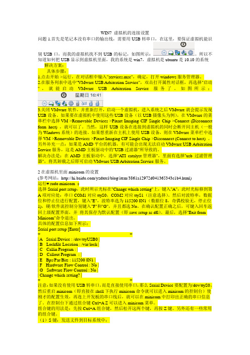
WIN7 虚拟机的连接设置问题1.首先是笔记本没有串口的输出线,需要用USB转串口,在这里,要保证虚拟机能识别USB口,而我的虚拟机找不到USB的标记,如图所示:。
所以不知道如何把USB显示到虚拟机里面,我的系统是win7,虚拟机是ubuntu是10.10的系统解决方案:具体步骤:1.点击开始->运行,在对话框中输入"services.msc",确定,打开windows服务管理器。
2.在服务列表中选中"VMware USB Arbitration Service",双击打开属性对话框,再选择"启动",就能启动VMware USB Arbitration Service服务了。
如图所示:3.关闭VMware软件,并重新打开,启动一个虚拟机,进入系统之后VMware就会提示发现USB设备。
如果要在虚拟机中使用这些USB设备(以USB摄像头为例),在VMware的菜单栏中选择VM->Removable Devices->Pixart Imaging CIF Single Chip->Connect (Disconnect form host) ,就可以了。
当然,这样USB设备在连接到虚拟机的同时会断开同主机(一般为Windows系统)的连接。
如果想重新在主机上使用USB设备,则在VMware菜单栏中选择VM->Removable Devices->Pixart Imaging CIF Single Chip->Disconnect (Connect to host) 。
另外补充一点:如果是AMD平台的机器,有可能会出现无法启动VMware USB Arbitration Service服务,这是AMD主板驱动中的"USB过滤器"所导致的。
解决办法是:在AMD主板驱动中,选择"A TI catalyst管理器",里面有选择"usb 过滤管理器",将其卸载之后即可启动VMware USB Arbitration Service服务。
Make Electronics Learning by Discovery说明书

Indexn AAndroid Droid X smartphone, 165Arduino-based LCD controllerwith an improved event trigger, 182with auto-adjust contrast control, 181block diagram, 189, 190circuit diagram, 187, 189delay() function, 197features, 187Hello World Sketch, 191–192, 195–197kit, 188with light detection, 182prototype, 190Serial Monitor Sketch, 193–194with simple event detection, 182talking Arduino, 192Arduino-based unipolar stepper motor controller actual build, 111circuit diagram, 111Darlington transistor driver, 110Easter egg, 112Knob sketch, 113Serial Monitor access, 114stepper_oneRevolution Sketch, 112Arduino Flasher-Tester systemblock diagram, 40circuit diagram, 41common anode display, 41, 42completed circuit, 42, 43potentiometer LED control sketch, 43–44 ATmega328 microcontrollerblock diagram, 66description, 65interactive light sequencer device, 59, 60pin out configuration, 123waveform generator, 124Audio transformercircuit diagram, 10closed switch, 13description, 9inverted pulsed waveform signals, 10, 11open switch, 12Auto-adjust contrast controlfor Arduino-based LCD controller, 198circuit diagram, 198, 199DC voltage measurement, 199, 200n BBase biasing transistor driver circuit, 72–747447 BCD-to-Decode IC, 44–46n CComputer thermometerblock diagram, 232circuit diagram, 233completed stageFarenheit temperature readings, 237LM35 Celsius Temperature Sketch, 237–238LM35 Farenheit Temperature Sketch, 238–239LM35 sensor, 236data start switch, 233, 235description, 232LM35 Sensor Sketch, 232–233Serial Monitor displaying sensor data, 233, 234temperature monitorblock diagram, 239circuit diagram, 239, 240LM35 Farenheit temperature with Dual LEDflash rates sketch, 242–243LM35 Farenheit temperature with flashing LEDsketch, 240–241251N INDEX252Computer thermometer (cont.)room temperature response, 241temperature sensorprototype, 234testing, 235n DDarlington transistorcircuit, 106description, 105unipolar stepper motor phase sequences, 106, 107DC motor controller, 80Digital multimeter (DMM), 16–18n EElectric motors, 80Electromechanical relayactive-high digital input circuit, 79IC socket, 78pinout, 78Electronic singing birdaudio transformercircuit diagram, 10closed switch, 13description, 9inverted pulsed waveform signals, 10, 11open switch, 12biasing, 3breadboard assembly2N3904 and 2N3906 transistors, 21prototype, 21, 22pulsed tone oscillator circuit, 20relay, 20, 21circuit diagram, 3, 6DMM, 16–18duty cycle, 7electronic oscillator circuit, 6interactive control softwareArduino processing editor, 23–24Button sketch code, 22–23description, 22light detection circuitsphotocells, 14–15using oscilloscope, 16, 18, 19using voltmeter, 16–18Multisim virtual oscilloscope, 4parts, 1–2physical computing, 2pulsed waveform signal, 5–6PWM, 7sketch, 23system block diagram, 2testing, 24–25transistor biasing, 7function generator, 9switching circuit, 8voltage divider, 12–14Electronic thermometercircuit diagram, 229computer ribbon cable, 229, 230description, 229LCDblock diagram, 243circuit diagram, 243description, 243prototype, 244sensor data to temperature sketch, 244–245LM35-based, 231LM35 precision centigrade temperature sensorIC T0-92 package, 231ribbon end connectors, 230n F, GFlexiForce sensor (FFS)hapticsblock diagram, 174circuit diagram, 175prototype, 175, 176Robot End Effector Test Stand, 177–178stepper_speedControl Sketch, 176–177servo motor controlFlexiForce-operated controller, 103, 104Fritzing circuit, 104input interface circuit, 103prototype, 105tactile force, 102Flyback diode, 74, 75Fritzing softwareArduino-based controller prototype, 95circuit, 94description, 94music box controller, 122sweep sketch, 95–96Function generator, 9n HHaptics controller systemblock diagram, 151description, 149discovery method, 178driver interface circuit, 150–152FlexiForce sensor hapticsblock diagram, 174circuit diagram, 175N INDEX253prototype, 175, 176Robot End Effector Test Stand, 177–178stepper_speedControl Sketch, 176–177285Hz PWM signal, 163, 164keypad hapticsbutton sketch, 171–172circuit diagram, 166, 167Grayhill 16 keypad, 169interface circuit testing, 170, 171Keypad_VibrationMotor_control Sketch, 172–173output voltage, 167pin identification, 168, 169prototype, 170Real Calculator app, 165switch matrix datasheet, 168truth table, 168virtual three-button keypad circuit model, 166mechatronics, 174parts, 149–150robotics-based haptics system, 151test and measurement setup, 164–165testing, 178vibration motorArduino computational platform, 153, 154Arduino port D5, 156, 15722AWG stranded wire, 153, 154circuit diagram, 158description, 152examples, 152Itotal measurement, 156joystick-controlled, 159–161PWM signal, 161–162Ra current measurement, 153, 155recycled, 153stepper motor control sketch, 162–163test sketch, 156working process, 152n IImproved Smart Logic Probe, 224–226Interactive control softwareArduino processing editor, 23–24Button sketch code, 22–23description, 22Interactive light sequencer deviceblock diagram, 52circuit diagram, 53LEDsATmega328 microcontroller, 59, 60fan-out, 59interactive LED sequencer device, 62parts layout, 62wiring diagram, 60, 61wiring prototyping tools, 61measurement setupexcel results, 58output frequency, 59procedure, 56prototype, 57resistance, 58resistance vs. voltage data table, 57voltage, 58parts, 51–52potentiometerdescription, 54symbol, 54, 55total resistance measurement, 54, 55voltage divider circuit, 55, 56remix design technique, 52block diagram, 53circuit diagram, 53, 54remixed interactive LED sequencer device, 63sequential-switching softwareATmega328 microcontroller, 65–67interactive LED light sequencer sketch, 64–65testing, 67Interactive music box controllerCdS photocell data, 145line of code, 143serial monitor, 143, 144tonePitchFollower sketch, 142–143n JJig systemsblock diagram, 183command-control codes, 184contact bounce and debounce circuitoperation, 185debounce circuit, 184, 185letters, numbers, and character codes, 188prototype, 187Joystick, servo motor controlcircuit diagram, 101description, 100mechanical linkage assembly, 100, 101prototype, 102soldered pigtail wire harness, 102n KKeypad hapticsbutton sketch, 171–172circuit diagram, 166, 167Grayhill 16 keypad, 169interface circuit testing, 170, 171N INDEX254Keypad haptics (cont.)Keypad_VibrationMotor_control Sketch, 172–173output voltage, 167pin identification, 168, 169prototype, 170Real Calculator app, 165switch matrix datasheet, 168truth table, 168virtual three-button keypad circuit model, 166n LLCD. See Liquid crystal display (LCD)LEDs. See Light emitting diodes (LEDs)Light detection circuitsphotocells, 14–15using oscilloscope, 16, 18, 19using voltmeter, 16–18Light emitting diodes (LEDs)ATmega328 microcontroller, 59, 60bar display, 32–34circuit analysis, 31–32fan-out, 59forward biasing mode, 30interactive LED sequencer device, 62multisim circuit model, 30parts layout, 62reverse biasing mode, 30, 31seven-segment displayArduino Flasher-Tester system, 40–44Arduino prototype, 219arrangements, 37BCD-to-Decimal circuit, 46–47circuit diagram, 212component, 38numbers creation, 211, 212serial monitor display, 219, 220sketch, 213–219testing, 38–40wiring diagram, 60, 61wiring prototyping tools, 61Liquid crystal display (LCD)Arduino-based controllerwith an improved event trigger, 182with auto-adjust contrast control, 181block diagram, 189, 190circuit diagram, 187, 189delay() function, 197features, 187Hello World Sketch, 191–192, 195–197kit, 188with light detection, 182prototype, 190Serial Monitor Sketch, 193–194with simple event detection, 182talking Arduino, 192auto-adjust contrast controlfor Arduino-based LCD controller, 198circuit diagram, 198, 199DC voltage measurement, 199, 200block diagram, 180–183description, 179discovery methods, 204electronic thermometerblock diagram, 243circuit diagram, 243description, 243prototype, 244sensor data to temperature sketch, 244–245evaluation boardlow-cost proto-evaluation breadboard, 204manual counter sketch, 201–203potentiometer, 201push-button switch, 200read sensor sketch, 203parts, 179–180remixing physical-computing input interfacecircuits, 180–183test jig systemsblock diagram, 183command-control codes, 184contact bounce and debounce circuitoperation, 185debounce circuit, 184, 185letters, numbers, and character codes, 188prototype, 187LM35computer thermometerCelsius Temperature Sketch, 237–238Farenheit Temperature Sketch, 238–239sensor sketch, 232–233electronic thermometer, 231precision centigrade temperature sensorIC T0-92 package, 231temperature monitorFarenheit temperature with dual LED flashrates sketch, 242–243Farenheit temperature with flashing LEDsketch, 240–241Logic checkerblock diagramArduino logic checker, 207basic logic checker, 208discovery methods, 226input interface circuits, 206NAND gatecircuit diagram, 209logic probe circuit diagram, 208N INDEX255open source logic probe kit, 210with seven-segment LED display, 211truth table, 209using Multisim, 210OR gate, 226parts, 205–206seven-segment LED displayArduino prototype, 219circuit diagram, 212numbers creation, 211, 212serial monitor display, 219, 220sketch, 213–219Smart Logic Probecircuit sketch, 220–223improved, 224–226prototype, 223truth table, 205working procedure, 206–208n MMini digital roulette games7447 BCD-to-Decode IC, 44–46bill of materials (BOM), 27block diagram, 28breadboard assembly, 47circuit diagram, 29forward biasing, 29game software, 35–37, 48LEDbar display, 32–34circuit analysis, 31–32forward biasing mode, 30multisim circuit model, 30reverse biasing mode, 30, 31new circuit design, 48–49parts, 27–28reverse bias, 30seven-segment LED displayArduino Flasher-Tester system, 40–44arrangements, 37BCD-to-Decimal circuit, 46–47component, 38testing, 38–40testing, 48version 1DIP package, 35prototype, 34Windows calculator, 32Motion controlDarlington transistorcircuit, 106description, 105unipolar stepper motor phase sequences, 106, 107remixing, 90–91servo motor control (see Servo motor control)stepper motor control (see Stepper motor control)Motor speed control2N2222 transistor pinout, 84potentiometer input controlArduino controlled DC motor, 83circuit diagram, 81controller prototype, 82PWM control signal, 84softwarelight detection input control, 85–86sketch, 85Multisim digital controller modelcircuit diagram, 108, 109CW/CCW timing diagrams, 110description, 108virtual Function Generator setup, 109Multisim virtual oscilloscope, 4Music box controllerblock diagramArduino-based physical-computing, 121keypad-activated, 121potentiometer-activated, 122remixed FlexiForce sensor-activated, 121building and testingbasic block diagram, 127circuit diagram, 128Code for Playing “Twinkle, Twinkle, Little Star,” 129–130Fritzing music box controller sketch, 127, 128with oscilloscope, PWM signal, 130–133physical prototype, 129discovery methods, 148driver interface circuits, 120–122driving a speakeradjusted PWM output signal, 135circuit diagram, with prototype, 133, 135Fritzing sketch, 134PWM output signal, 133, 134Fritzing model, 122interactive, 141CdS photocell data, 145line of code, 143serial monitor, 143, 144tonePitchFollower sketch, 142–143parts, 119–120piezo-buzzer, 122PMOSFETdescription, 136Multisim circuit model, 137–141N-channel PMOSFET (IRF630A) pinout, 136P-channel electrical symbol, 136, 137N INDEX256Music box controller (cont.)PWMATmega328 Microcontroller, 123–124Multisim function generator setup, 126Multisim PWM virtual circuit, 124, 125one-shot component configuration, 125, 126triangle wave, 125, 127value table, 125remixing physical-computing, 120–122testing, 148three-keycircuit diagram, 145, 146prototype, 146toneKeyboard Sketch, 147working procedure, 122n NNAND gatecircuit diagram, 209logic probe circuit diagram, 208open source logic probe kit, 210with seven-segment LED display, 211truth table, 209using Multisim, 210N-channel PMOSFET (IRF630A), 136n OOR gate, 226Oscilloscopeambient and no ambient lighting, 18, 19laboratory test bench setup, 18, 19multisim circuit diagram, 16, 18n P, QP-channel MOSFET, 136, 137Physical-computing DC motor control systemsbase biasing transistor driver circuit, 72–74block diagram, 71DC motor controller, 80electric motors, 80electromechanical relay preparationactive-high digital input circuit, 79IC socket, 78pinout, 78energization, 74flyback diode, 74, 75motor speed control2N2222 transistor pinout, 84potentiometer input control, 81–84software, 85–86multisim circuit transistor driver models, 73–74parts, 69–70remix design technique, 70, 71testing, 87transistor relay driverblock diagram, 71circuit diagram, 72DC motor control circuit, 75–77PMOSFETdescription, 136Multisim circuit modelLED driver demonstration circuit, 137–138remixed interactive music box controller,138–141N-channel PMOSFET (IRF630A) pinout, 136P-channel electrical symbol, 136, 137Potentiometerinteractive light sequencer devicedescription, 54symbol, 54, 55total resistance measurement, 54, 55voltage divider circuit, 55, 56motor speed controlArduino controlled DC motor, 83circuit diagram, 81controller prototype, 82PWM control signal, 84servo motor controlcircuit diaram, 98Fritzing circuit, 98Knob sketch, 99, 100prototype, 99Precision centigrade temperature sensor, 228Pulse width modulation (PWM)electronic singing bird, 7music box controllerATmega328 Microcontroller, 123–124Multisim function generator setup, 126Multisim PWM virtual circuit, 124, 125one-shot component configuration, 125, 126triangle wave, 125, 127value table, 125signal, vibration motor, 161–162n RRemix design techniqueinteractive LED sequencer device, 63interactive light sequencer deviceblock diagram, 53circuit diagram, 53, 54Remixed interactive music box controllerblock diagram, 138Fritzing circuit diagram, 138, 139prototype, with cricuit diagram, 139N INDEX257PWM signalunder ambient lighting, 140with hand passing over the photocell, 140Piezo buzzer, 141Robot end effector test stand application, 177–178n SSequential-switching softwareATmega328 microcontroller, 65–67interactive LED light sequencer sketch, 64–65Servo motor controlArduino-based computing platform, 92Arduino-based system block diagram, 90controlling with Arduino, 93discovery methods, 117FFSFlexiForce-operated controller, 103, 104Fritzing circuit, 104input interface circuit, 103prototype, 105tactile force, 102Fritzing softwareArduino-based controller prototype, 95circuit, 94description, 94sweep sketch, 95–96joystickcircuit diagram, 101description, 100mechanical linkage assembly, 100, 101prototype, 102soldered pigtail wire harness, 102negative feedback, 93parts, 89, 90potentiometer, 97circuit diaram, 98Fritzing circuit, 98Knob sketch, 99, 100prototype, 99pulse widths, 92remixed FlexiForce sensor-activated blockdiagram, 91testing, 116wiring, 93Seven-segment LED displayArduino Flasher-Tester systemblock diagram, 40circuit diagram, 41common anode display, 41, 42completed circuit, 42, 43potentiometer LED Control Sketch, 43–44Arduino prototype, 219arrangements, 37BCD-to-Decimal circuit, 46–47circuit diagram, 212component, 38numbers creation, 211, 212serial monitor display, 219, 220sketch, 213–219testing, 38–40Smart Logic Probecircuit sketch, 220–223improved, 224–226prototype, 223Speed control functioncircuit diagram, 115stepper_speedControl Sketch, 115–116Stepper motor controlArduino-based system block diagram, 91discovery methods, 117parts, 89, 90remixed FlexiForce sensor-activatedblock diagram, 91testing, 116unipolar (see Unipolar Stepper Motor)n TTemperature controllercircuit diagram, 245, 246description, 245prototype, 245, 248sketch, 246–247Temperature measurementcomputer thermometerblock diagram, 232circuit diagram, 233data start switch, 233, 235description, 232final completion, 235–239LM35 Sensor Sketch, 232–233Serial Monitor displaying sensor data, 233, 234temperature monitor, 239–243temperature sensor prototype, 233, 234testing temperature sensor, 233, 235description, 227digital voltmeter system block diagram, 229discovery method, 248electronic thermometercircuit diagram, 229computer ribbon cable, 229, 230description, 229LM35-based, 231LM35 precision centigrade temperature sensor IC T0-92 package, 231ribbon end connectors, 230N INDEX258Temperature measurement (cont.)LCD electronic thermometerblock diagram, 243circuit diagram, 243description, 243prototype, 244Sensor Data to Temperature Sketch, 244–245parts, 227–228precision centigrade temperature sensor, 228temperature controllercircuit diagram, 245, 246description, 245prototype, 245, 248sketch, 246–247working procedure, 228–229Temperature monitorblock diagram, 239circuit diagram, 239, 240LM35 Farenheit Temperaturewith Dual LED Flash RatesSketch, 242–243with Flashing LED Sketch, 240–241room temperature response, 241Test jig systemsblock diagram, 183command-control codes, 184contact bounce and debouncecircuit operation, 185debounce circuit, 184, 185letters, numbers, and character codes, 188prototype, 187Three-key music box controllercircuit diagram, 145, 146prototype, 146toneKeyboard Sketch, 147Transistor biasing, 7function generator, 9switching circuit, 8Transistor relay driverblock diagram, 71circuit diagram, 72DC motor control circuitArduino-based circuit diagram, 77circuit diagram, 75multisim circuit model analysis, 76n UUnipolar stepper motorArduino-basedactual build, 111circuit diagram, 111Darlington transistor driver, 110Easter egg, 112Knob sketch, 113Serial Monitor access, 114stepper_oneRevolution Sketch, 112description, 107Multisim digital controller modelcircuit diagram, 108, 109CW/CCW timing diagrams, 110description, 108virtual Function Generator setup, 109sink driver circuit, 107, 108speed control function, 114circuit diagram, 114, 115stepper_speedControl Sketch, 115–116n V, X, Y, ZVibration motorArduino computational platform, 153, 154Arduino port D5circuit diagram, 157Itotal, 159output voltage, 156, 15722AWG stranded wire, 153, 154circuit diagram, 158description, 152examples, 152Itotal measurement, 156joystick-controlledblock diagram, 159, 160circuit diagram, 160prototype, 161PWM signal, 161–162Ra current measurement, 153, 155recycled, 153stepper motor control sketch, 162–163test sketch, 156Voltage divider, electronic singing bird, 12–14。
- 1、下载文档前请自行甄别文档内容的完整性,平台不提供额外的编辑、内容补充、找答案等附加服务。
- 2、"仅部分预览"的文档,不可在线预览部分如存在完整性等问题,可反馈申请退款(可完整预览的文档不适用该条件!)。
- 3、如文档侵犯您的权益,请联系客服反馈,我们会尽快为您处理(人工客服工作时间:9:00-18:30)。
ROHM LCD Driver for Small Display ApplicationsMar. 2011 Digital IC Team MCU2G ROHM Co., LTD.Confidential c 2009 ROHM Co.,Ltd. All Rights ReservedSegment LCD driver : IntroductionSegment LCD driver is useful solution to adopt segment LCD display.1Electricity meterMeasurement equipmentClock displayStatus indicatorTelephoneFAXInstruments, Key boardTime loggerIs the following problem existing in your application? The lack of pin numbers in the micro controller by LCD module The wiring issue between the micro controller and LCD moduleConfidential c 2009 ROHM Co.,Ltd. All Rights ReservedMeter SystemEnergy metering2Single-phase meterVoltage detector Communication Infrared RS485 GPRS ZIGBEE PLC moduleTem detector EEPROMMCURTC X’talSegment driverBatteryROHM product Under planning No this productLCD panelConfidential c 2009 ROHM Co.,Ltd. All Rights ReservedSmart Meter Proposal by ROHM/OKI・ML610Q400 series ・80SEG(20seg×4com) BU9796FS ・140SEG(35seg×4com) BU9795FV ・200SEG(50seg×4com) BU9799KV LCD3Power lineRS-485AFE Vsense PGA Sigma-Delta ADC 14b-16bLCD Segment DriverCommunication InterfaceMicro Processor 8b / 16b / 32bE2PROM3VZigbee Bluetooth Wireless LAN etc.CT IsenseHome Area Network (HAN) Power Line Comm. (PLC)RTC module RTC onlyP2ROM FeRAMUSB UART SPIEnergy metering (AC / DC) BAT detect MP Under development Future Target Power Supply ・REG BA178MXX series ・DC/DC BD97XX series BD91XX series LDO LDO LDORF ID(TAG) System(Option)Reference 1.2VTemp Sensor・MR26T series ・MR27T series・BR24L/S series(I2C) ・BR25L/S series(SPI) ・BR93L/S seried(MW)Confidentialc 2009 ROHM Co.,Ltd. All Rights ReservedSegment LCD driver : Advantages1. Cost reduction4Just serial interface is needed for segment LCD control on the micro controller. Many pins are not required. It is possible to reduce the cost for the micro controller by small number of pin, and small connector for PCB/cable.•Flexible designIt is easy to use different segment LCD modules for wide model lineup by just changing segment driver. The substrate design and the PCB layout can be designed by the number of wiring decreasing freely.u-comu-com Segment DriverThe conventional systemThe system with segment driverConfidentialc 2009 ROHM Co.,Ltd. All Rights ReservedSegment LCD Driver : ROHM advantagesSwap Segment / GPO outputSelect Segment output or GPO output.5 Ultra low power design TYP 5uA @Ta =RoomSupport GPO outputGPO output can help lack of u-con port number .Other LSI / LED................ SEGMENTC O M M O N3ch LED driveGPO Segment Driver Common DriverIntegrated Buffer AMP LED Driver Data LatchPower Supply for LCD We can achieve low power consumption.Support Static Driving PWM Gen. Integrated LED Driver and PWM generatorWe can achieve LED drive around LCD without u-con load and external FET.Display data Blink data Timing Gen.We can support static driving for visual quality improvement.I/FOscillator Support Blink functionWe can support individual blink function.Confidentialc 2009 ROHM Co.,Ltd. All Rights ReservedSegment LCD Driver : Ultra low power designUltra low power designOptimize Driver ability6TYP 5uA @Ta =RoomWe optimized SEG/COM driver ability for segment driver application.GPOSegment DriverCommon DriverLow power AMP technology C-less AMP technologyWe modified Low power AMP technology from mobile LCD driver technology for segment Driver applicationPWM generatorWe achieve low power circuit For PWM generator.LED DriverData LatchPower Supply for LCDPWM Gen.Display data Blink data Timing Gen.I/FOscillator Low power Oscillator technologyConfidentialc 2009 ROHM Co.,Ltd. All Rights ReservedPower Consumption comparisonPower consumption comparison with “B” company4COM x 40SEG, I2C bus,7BU9799 Current [uA] VDD=2.5V Freq. [Hz] 67.8“B” company Current [uA] 12.0 Freq. [Hz] 52.34.5VDD=3.5V5.972.914.654.3VDD=5.5V9.878.619.957.1VLCD=0V, Ta=RoomROHM segment driver is more than 50% low power consumption comparison with “B” company.Confidentialc 2009 ROHM Co.,Ltd. All Rights ReservedSegment LCD Driver : Anti-jam abilityESDLevel 1 2 3 Voltage 2kv 4kv 8kv 15kv8Air discharge (Round head,Discharge then touch the device,16kV)Contact discharge (Sharp head,To metal part,8kV)Contact discharge (Sharp head,from coupling board,16kV)4EFTBU9796:4.5KV 5KHz okPower, Ground Level Voltage peak(kV) 0.5 1 2 4 F(KHz) 5 5 5 2.5I/O port Voltage peak(kV) 0.25 0.5 1 2 F(KHz) 5 5 5 51 2 3 4ROHM advantage : Ultra strong anti-jam ability • HBM:8kV • MM:600V Air discharge 16kV Contact discharge 8kVConfidentialc 2009 ROHM Co.,Ltd. All Rights ReservedSegment LCD Driver : GPO and LED drive functionROHM GPO function help the lack of pin Numbers in the micro controller .Selectable GPO portWe support maximum 31port for GPO pot from Segment Driver port. (BU9798 case)9Other LSI / LED3ch LED driveGPO Segment Driver Common DriverLED Driver Support LED Driver and PWM generatorWe integrated LED driver and PWM generator. This function will help to reduce external components and micro controller load.Data LatchPower Supply for LCDPWM Gen.Display data Blink data Timing Gen.I/FOscillatorConfidentialc 2009 ROHM Co.,Ltd. All Rights ReservedSegment LCD Driver : Independent blink function10ONOFFONGPOSegment DriverCommon DriverLED DriverData LatchPower Supply for LCDPWM Gen.Display data Blink data Timing Gen.Support independent blink functionWe control blink function and display function independently. We can support each 1dot blink function. This function will help to reduce micro controller load.I/FOscillatorConfidentialc 2009 ROHM Co.,Ltd. All Rights ReservedSegment LCD Driver 1: Line-up • BU9793FS20seg×4 com = 80 output ×11• BU9795 (max)35 seg ×4 com = 140output• BU9792AFUV36 seg ×4 com = 144output• BU9799KV50 seg ×4 com = 200outputOutputs Display SEG Operating Voltage Duty Bias Interface RAM Ultra Low Power EVR LDO GPO LED Dr PWM Gen. Package I/F Power LCD Power COM Supply(VDD) Supply(VLCD)BU9793FS80dots2042.5V~5.5V1/41/2,1/32line serialOO-----SSOPA-32BU9795Max 140dots3542.5V~5.5V1/41/2,1/33line serialOO-----VQFP48CBU9792AFUV144dots3642.5V~5.5V2.5V~5.5V1/41/2,1/32line serialOO-----TSSOP48BU9799KV200dots5042.5V~5.5V2.5V~5.5V1/41/2,1/32line serialOOO----VQFP64Confidentialc 2009 ROHM Co.,Ltd. All Rights ReservedBU9792AFUV: 144(36*4)segments LCD driverBU9792AFUV is a up-to 144segment LCD driver suitable for use with a micro controller and IIC interface. ■ Features■ Display Data RAM(DDRAM) : 36 * 4bit ( 144segments) ■ LCD driving output : 4 common output 36 segment output ■ Built in power supply for LCD driver Duty cycle: 1/4, Bias: 1/3, 1/2bias ■ Blinking function ■ Integrated Power on reset, Oscillator circuit ■ 2 wire serial interface (SDA, SCL) ■ Support register read ■ Schmitt circuit inside ■ Power supply : 2.5 to 5.5V ■ LCD Power supply: 2.5to 5.5V ■ Ultra low power consumption Operation:7.5uAOSCIN OSCILLATOR Power On Reset Command register Command Data Decoder VLCD+ - + -12■ Block diagramCOM0……COM3 VDD LCD voltage generator common driver Segment driver SEG0……SEG35LCD BIAS SELECTOR common counter blink timing generator DDRAMserial inter face■ PackageIF FILTER VSSTSSOP-C48 8.1mm * 12.5mm * max1mm 0.5mm pitchSDASCLConfidentialc 2009 ROHM Co.,Ltd. All Rights ReservedBU9793FS: 80(20*4)segments LCD driverBU9793FS is a up-to 80segment LCD driver suitable for use with a micro controller and IIC interface. ■ Features■ Display Data RAM(DDRAM) : 20 * 4bit ( max 80 segments) ■ LCD driving output : 4 common output 20 segment output ■ Built in power supply for LCD driver Duty cycle: 1/4, Bias: 1/3, 1/2bias ■ Blinking function ■ Integrated Power on reset, Oscillator circuit ■ 2 wire serial interface (SDA, SCL) ■ Power supply : 2.5 to 5.5V ■ LCD Power supply: 2.5to 5.5V ■ Ultra low power consumption Operation:5uACommand register OSCILLATOR Power On Reset Command Data Decoder VLCD+ - + -13■ Block diagramCOM0……COM3 VDD LCD voltage generator common driver Segment driver SEG0……SEG19LCD BIAS SELECTOR common counter blink timing generator DDRAMOSCINserial inter face■ PackageIF FILTER VSS SDA SCLSSOP-A32 7.8mm * 13.6mm * max 1.5mm 0.5mm pitchConfidentialc 2009 ROHM Co.,Ltd. All Rights ReservedBU9795:Max140(27/31/35*4)segments LCD driverBU9795** is a series which up-to 140segment LCD driver suitable for use with a micro controller and 3wire series interface. ■ Features■ Display Data RAM(DDRAM) : 27/31/35* 4bit ( 108,124,140 segments) ■ LCD driving output : 4 common output Max 35 segment output ■ Built in power supply for LCD driver Duty cycle: 1/4, Bias: 1/3, 1/2bias ■ Blinking function ■ Integrated Power on reset, Oscillator circuit ■ 2 wire serial interface (SD, SCL,CSB) ■ Power supply : 2.5 to 5.5V ■ LCD Power supply: 2.5to 5.5V ■ Ultra low power consumption Standby:Max 5uA(Display off,,Oscillator off) Operation:12.5uAVLCD+ - + -14■ Block diagramCOM0……COM3 VDD LCD voltage generator common driver Segment driver SEG0……SEG34LCD BIAS SELECTOR common counter blink timing generator DDRAMINHb OSCIN OSCILLATOR Power On Reset Command register Command Data Decoder■ PackageVQFP48C 9mm * 9mm * max 1.6mm, 0.5mm pitch SSOP-B40 7.8mm*13.6 mm*Max 1.8mm 0.65mm pitch VBGA48W040 4mm*4mm*Max0.8 0.5mm pitchVSSserial inter faceIF FILTERTESTCSBSDSCLConfidentialc 2009 ROHM Co.,Ltd. All Rights ReservedBU9799KV : 200(50*4)segments LCD driverBU9799KV is a up-to 200segment LCD driver suitable for use with a micro controller and IIC interface. ■ Features■ Display Data RAM(DDRAM) : 50 * 4bit ( max 200 segments) ■ LCD driving output : 4 common output 50 segment output ■ Built in power supply for LCD driver Duty cycle: 1/4, Bias: 1/3, 1/2bias ■ Blinking function ■ Integrated Power on reset, Oscillator circuit ■ 2 wire serial interface (SDA, SCL) ■ Power supply : 2.5 to 5.5V ■ LCD Power supply: 2.5to 5.5V ■ Ultra low power consumption Standby:1uA Operation:12.5uA ■ EVR functionINHb OSCIN Command register OSCILLATOR Power On Reset Command Data Decoder VSS+ - + -15■ Block diagramCOM0……COM3 VLCD LCD voltage generator common driver Segment driver SEG0……SEG49LCD BIAS SELECTOR common counter blink timing generator DDRAM■ PackageVDD VSSserial inter faceIF FILTERVQFP-64 12mm * 12mm * max 1.5mm 0.5mm pitchTEST2 TEST1 CSB SDA SD SCLConfidentialc 2009 ROHM Co.,Ltd. All Rights ReservedSegment LCD Driver 2: New product • BU97930MUV27 seg×4 com = 108 output ×16• BU97931FV28 seg ×4 com = 112output• BU9798KV/GUW49 seg ×4 com = 196output• BU97950FUV35 seg ×8 com = 280outputOutputs NEW Display SEG COM Operating Voltage I/F Power LCD Power Supply(VDD) Supply(VLCD) Duty Bias Interface RAM Ultra Low Power EVR LDO GPO LED Dr PWM Gen. PackageBU97930MUV108dots2741.8V~3.6V2.7V~5.5V1/4, 1/3, 1/3, Static Static 1/4, 1/3, 1/3, Static Static 1/4, 1/3, 1/3, Static Static 1/8 1/43line serial 3line serial 3line serial 2line serialOO--O 4port O 5port O 31port -O 1port O 1port O 3port -O 1ch O 1ch O 2ch -VQFN40V6060BU97931FV112dots2841.8V~3.6V2.7V~5.5VOO--SSOP-B40BU9798KV/GUW196dots4941.8V~3.6V3.3V~5.5VOO-OVQFP64/ VBGA063W050 TSSOP-48BU97950FUV Under development280dots3582.5V~5.5V2.5V~5.5VOOOConfidentialc 2009 ROHM Co.,Ltd. All Rights ReservedBU97931FV : 112(28*4)segments LCD driverBU97931FV is a up-to 112 segment LCD driver suitable for use with a micro controller and 3wire serial interface. ■ Features■ Display Data RAM(DDRAM) : 28 * 4bit ( max 112 segments) ■ LCD driving output : 4 common output 28 segment output ■ Built in power supply for LCD driver Duty cycle: 1/4, 1/3, static , Bias: 1/3, 1/1bias ■ Blinking function ■ Integrated Power on reset, Oscillator circuit ■ Integrated Buffer AMP for LCD power supply ■ Integrated 5ch GPO port ■ Integrated 1ch LED Driver and PWM generator ■ 3wire serial interface (SD, SCL, SCB) ■ I/F Power supply : 1.8 to 3.6V ■ LCD Power supply: 2.7 to 5.5V ■ Ultra low power consumptionCLKIN OSCILLATO R Power On Reset Serial Interface Command Register Dat a Dec oder VSS LCD BIAS SELECTOR Common Counter Blink Timing Generator DDRAM GPO dat a latch GPO Controller VLCD LCD voltage Generator Common Driver Segment Driver Segment Driver/GPO LED Driver COM0 COM3 SEG0 ..22, SEG23 27 LED17■ Block diagramPWM Generator■ PackageVDD VSSI F FILTERSSOP-B40 13.6mm * 7.8mm * max 1.8mm 0.65mm pitchCSBSDSCLConfidentialc 2009 ROHM Co.,Ltd. All Rights ReservedBU9798KV/GUW : 196(49*4)segments LCD driverBU9798KV/GUW is a up-to 196 segment LCD driver suitable for use with a micro controller and 3wire serial interface. ■ Features■ Display Data RAM(DDRAM) : 49 * 4bit ( max 196 segments) ■ LCD driving output : 4 common output 49 segment output ■ Built in power supply for LCD driver Duty cycle: 1/4, 1/3, static , Bias: 1/3, 1/1bias ■ Blinking function ■ Integrated Power on reset, Oscillator circuit ■ Integrated 31ch GPO port ■ Integrated 3ch LED Driver and 2ch PWM generator ■ Integrated Regulator (LDO) for LCD power supply ■ 3wire serial interface (SD, SCL, SCB) ■ I/F Power supply : 1.8 to 3.6V ■ LCD Power supply: 3.3 to 5.5V ■ Ultra low power consumptionINHb Command register Data Dec oder OSCILLATOR Power On Reset VSS VLCD LCD voltage Generator Ref Voltage Circuit Vreg LCD BIAS SELECTOR Common Counter Blink Timing G enerator DDRAM GPO Data Latch GPO/LED Controller Common Driver Segment Driver Segment Segment Driver/GPO Driver/LED VSS2 COM0 COM3 SEG 0 SEG4818■ Block diagramPWM GeneratorCLKIN■ PackageVBGA063W050 5mm * 5mm * max 0.9mm 0.5mm pitch VQFP-64 12mm * 12mm * max 1.5mm 0.5mm pitchSerial I nterface Output Controller IF FILTERVDD VSSCSBSDSCLPWMO UTConfidentialc 2009 ROHM Co.,Ltd. All Rights ReservedBU97950FUV : 280(35*8)segments LCD driverBU97950FUV is a up-to 280 segment LCD driver suitable for 8COM LCD panel.19■ Features■ Display Data RAM(DDRAM) : 35* 8bit ( max 280 segments) ■ LCD driving output : 8 common output 35 segment output ■ Built in power supply for LCD driver Duty cycle: 1/8, Bias: 1/4bias ■ Support Register Read function ■ Integrated Power on reset, Oscillator circuit ■ Support EVR function ■ 2wire serial interface (SDA, SCL) ■ I/F Power supply : 2.5 to 5.5V ■ LCD Power supply: 2.5 to 5.5V ■ Ultra low power consumption■ Block diagramCOM 0 V LC D LC D v o lt ag e g en er ato r Co m mo n D r iv e r+ -COM 7SE G0S EG 3 4Se gm en t D riv e r+ -LC D BIA S S E LE C TO R C om m on C ou nte r D D RA M+ -+ -V SSC om m an d R eg is t er O S C ILL AT O R P ow er O n R es e tC om m an d D ata D ec o de rSe ria l I nte r fac e■ PackageVD DIF F IL T ERS DASC LTSSOP-C48V 8.1m * 12.5mm * max 1.0mm 0.5mm pitchConfidentialc 2009 ROHM Co.,Ltd. All Rights ReservedSegment LCD Driver : Line-upFor General purposeOutputs Display SEG BU9796FSNEW20Operating Voltage Duty Bias Interface RAM I/F Power Supply(VDD) LCD Power Supply(VLCD) 1/4 1/2,1/3 2wire serial ○ ○ ○Low PowerEVRGPO LED DrCOM 4Indepe PWM ndent Gen. BlinkPackage80dots202.5V~5.5V◎ ◎ ◎-○ 4port ○ 5port -○ 1port ○ 1port -○ 1ch ○ 1ch ○ 2ch -○ ○SSOPA-32BU97930MUV108dots2741.8V~3.6V2.7V~5.5V1/4, 1/3, 1/3, 3wire serial Static Static 1/4, 1/3, 1/3, 3wire serial Static Static 1/4 1/2,1/3 3wire serial-VQFN040W060NEWBU97931FV BU9795AKV /FV/GUW112dots MAX 140dots2841.8V~3.6V2.7V~5.5V-SSOP-B40 VQFP48C/ SSOP-B40/ VBGA048W040 VQFP64/ VBGA063W050 VQFP643542.5V~5.5V○◎--NEWBU9798KV/GUW 196dots4941.8V~3.6V3.3V~5.5V1/4, 1/3, 1/3, 3wire serial Static Static 1/4 1/2,1/3 3wire serial○ ○ ○ ○ ○◎ ◎ ◎ ○ ◎-○ ○ 31port 3port -○BU9794KV200dots5042.5V~5.5V2.5V~5.5V○ ○ ○-BU9799KVNEW200dots5042.5V~5.5V2.5V~5.5V1/41/2,1/3 2wire serial○ 4port ----VQFP64BU97500KV204dots5142.7V~5.5V 2.5V~5.5V ~4.5V~5.5V 2.5V~5.5V ~1/4, 1/3 1/2,1/3 3wire serial---VQFP64BU97950FUV280dots3581/81/42wire serial---TSSOP-C48VUnder developmentConfidentialc 2009 ROHM Co.,Ltd. All Rights ReservedConfidentialc 2009 ROHM Co.,Ltd. All Rights Reserved。