H9926S中文资料
中日材质对照
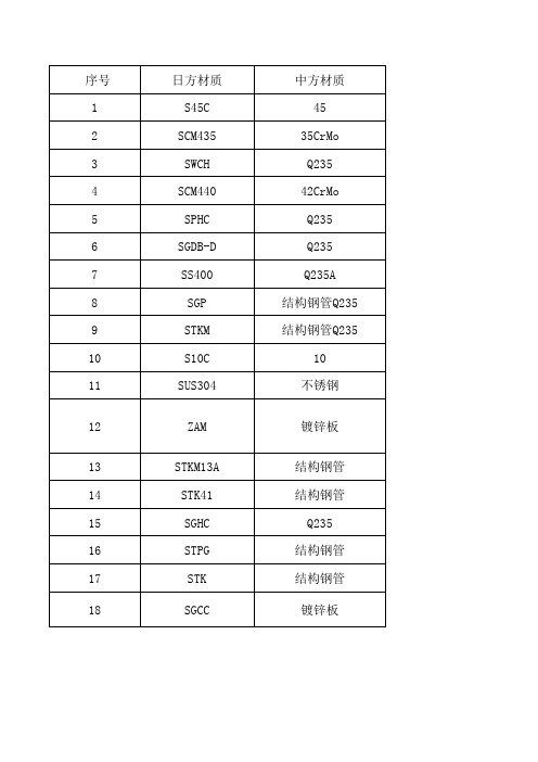
JIS G3302 SGHC 是日本标准,以热轧为基板的普通用热镀锌材质
SGCC 是热浸镀锌板 是接近银白色的 SECC 是冷轧镀锌板 是接近灰色的
SPHC这个牌号其实最早是德国的牌号,日本也用,后来国内钢厂宝钢引入, 代表的是的热轧钢板(它对应的冷轧板就是SPCC),相当于国标GB699(优 质碳素结构钢国家标准)中的10#、15#钢的热轧板,他们的含碳量范围是0.10.15% 左 右 。 SPHC 跟 Q235 之 类 的 不 可 相 互 转 换 , 因 为 Q235 遵 循 的 是 国 标 GB700(碳素结构钢国家标准)的标准,如果仅仅从含碳量上来讲,SPHC跟 Q215 8 9 10 11 12 13 14 15 16 17 18
日方材质 S45C SCM435 SWCH SCM440 SPHC SGDB-D SS400 SGP STKM S10C SUS304 ZAM STKM13A STK41 SGHC STPG STK SGCC
中方材质 45 35CrMo Q235 42CrMo Q235 Q235 Q235A 结构钢管Q235 结构钢管Q235 10 不锈钢 镀锌板 结构钢管 结构钢管 Q235 结构钢管 结构钢管 镀锌板
SPHC/SPCC
备注
0Cr18Ni9
最近,一种名为ZAM(锌、铝、镁英文打头字母简称)的高耐腐蚀新型环保型钢板,由侨江集团旗下的上海统嘉实业有限公司从日本引进,进入上海钢 材市场。该产品亮相伊始,就因其所采取的新技术、新工艺而具备了防腐耐蚀的特性,成为钢材市场中的新秀,引起用户的关注。 “ZAM”,就是在它 的板材中添加了合适比例的锌、铝、镁,使其产生复合效果,具 有高强度的抗腐蚀性。试验及应用表明,其耐腐蚀性是一般镀锌钢板的15倍,是含 锌5%铝合金钢板的5?8倍,特别是在严酷的腐蚀环境下仍然保持钢板的原来面貌,减少了一般钢材后期加工工艺,降低了使用后续成本。同时由于减 少了电镀,该产品节约了资源亦保护了环境。 据日前在产品发布会上侨江集团和日方专家介绍,ZAM高耐腐蚀钢板的特点显著,可以广泛应用于工农 业项目、基建项目,特别是沿海地区的堤坝、桥梁和冶金、化工、下水道等一些腐蚀性较强地区。在量大面广的民用住宅建筑上,该产品在梁、柱及 墙体附着物的支撑结构、部件等应用上,有更大的优势。在性能价格比上亦能体现出比不锈钢与镀锌钢板的优势,是一种防锈抗腐的好材料。
HM92资料

Page No. : 1/3HM92PNP EPITAXIAL PLANAR TRANSISTORDescriptionThe HM92 is designed for application as a video output to drivecolor CRT, or as a dialer circuit in electronics telephone.Absolute Maximum Ratings• Maximum TemperaturesStorage Temperature............................................................................................ -55 ~ +150 °C Junction Temperature.................................................................................... +150°C Maximum • Maximum Power DissipationTotal Power Dissipation (Ta=25°C)...................................................................................... 1 W • Maximum Voltages and Currents (Ta=25°C)VCBO Collector to Base Voltage..................................................................................... -300 V VCEO Collector to Emitter Voltage.................................................................................. -300 V VEBO Emitter to Base Voltage............................................................................................ -5 V IC Collector Current...................................................................................................... -500 mA Characteristics (Ta=25°C)Symbol Min.Typ.Max.Unit Test ConditionsBVCBO-300--V IC=-100uA, IE=0BVCEO-300--V IC=-1mA, IB=0BVEBO-5--V IE=-10uA, IC=0ICBO---250nA VCB=-200V, IE=0IEBO---100nA VEB=-3V, IC=0*VCE(sat)---500mV IC=-20mA, IB=-2mA*VBE(sat)---900mV IC=-20mA, IB=-2mA*hFE125--VCE=-10V, IC=-1mA*hFE240--VCE=-10V, IC=-10mA*hFE325--VCE=-10V, IC=-30mAfT50--MHz VCE=-20V, IC=-10mA, f=100MHz Cob--6pF VCB=-20V, IE=0*Pulse Test : Pulse Width ≤380us, Duty Cycle≤2%Page No. : 2/3 Characteristics CurvePage No. : 3/3 SOT-89 DimensionImportant Notice:• All rights are reserved. Reproduction in whole or in part is prohibited without the prior written approval of HSMC.• HSMC reserves the right to make changes to its products without notice.•HSMC semiconductor products are not warranted to be suitable for use in Life-Support Applications, or systems.• HSMC assumes no liability for any consequence of customer product design, infringement of patents, or application assistance. Head Office And Factory :•Head Office (Hi-Sincerity Microelectronics Corp.) : 10F.,No. 61, Sec. 2, Chung-Shan N. Rd. Taipei Taiwan R.O.C.Tel : 886-2-25212056 Fax : 886-2-25632712, 25368454•Factory 1 : No. 38, Kuang Fu S. Rd., Fu-Kou Hsin-Chu Industrial Park Hsin-Chu Taiwan. R.O.CTel : 886-3-5983621~5 Fax : 886-3-5982931•Factory 2 : No. 17-1, Ta-Tung Rd., Fu-Kou Hsin-Chu Industrial Park Hsin-Chu Taiwan. R.O.CTel : 886-3-5977061 Fax : 886-3-5979220。
Parker Hose 产品目录说明书
More of what you need to work smarter,AccessoriesV i s u a l I n d e x59RG D-17T1RG D-17Partek Sleeve D-18ParKoil™ (PG) D-19GuardsO-Rings for CA, CE,CF MetricFlange “D” Rings Caterpillar ® Style FlangesT ube O-Ring Fittings and CompressorFittingsO-Rings for Compression Fittings (IT126)O-Rings for C9, OC, 1C Metric Swivels88HC-H Clamp D-2488DB Clamp D-24Hose Assembly D-26Workstations3/4 Reel Rack D-2772B-Cabinet D-28HR6 Hose Bin D-28Hose Adapters D437° Flare Metric Triple-Lok ®Sizes: 6 mm – 38 mmMaterials : Steel, Stainless Steel Pressures : Up to 7200 psi60° Cone BSPPK4Sizes : 1/8” – 2”Materials : Steel Pressures : Up to 5000 psi30° Flare Komatsu StyleSizes : M14 x 1.5 – M33 x 1.5Materials : Steel Pressures : Up to 4000 psiO-Ring Face-Seal Metric Seal-Lok™Sizes: 1/4” – 2”Materials: Steel, Stainless Steel Pressures: Up to 9200 psiJapanese Industrial Standard JISSizes : 1/4” – 1”Materials : Steel Pressures : Up to 5000 psiWhen ordering Parker Adapters, please state the Catalogued Number of each type of adapter desired. Be sure to double check tube and hose sizes of items required.To select proper seal materials for specific applications, refer to Media Compatibility Chart in Tube Fitting Catalog 4300, or contact your Parker Tube Fitting Distributor.If in doubt about which type or size of fitting to specify, consult your Parker Tube Fitting Distributor. In addition Parker Field Sales, Technical Services,the Tube Fitting Division and your local Parker Service Center will help you find answers to all your issues.Phone: (614) 279-7070Fax: (614) 279-7685Web: /tfdNote: Refer to Parker Catalog 4300 for more detailed application information.CALL TOLL-FREE 1-800-C PARKER (1-800-272-7537)Parker Information Center for catalogs, literature or additional information.O-Ring Face-Seal Seal-Lok™ Sizes: 6 mm – 38 mm Materials: Steel, Stainless Steel Pressures: Up to 9200 psi37° Flare FittingsTriple-Lok ®Sizes: 1/8” – 2”Materials: Steel, Stainless Steel, BrassPressures: Up to 9000 psiPipe Fittings and Port AdaptersSizes: 1/8” – 2”Materials : Steel, Stainless Steel, BrassPressures : Up to 7200 psiPipe SwivelsSizes : 1/8” – 2”Materials : Steel, Stainless Steel Pressures : Up to 5000 psiConversion AdaptersSizes: 1/4” – 1-1/2”Materials : Steel, Stainless Steel Pressures : Up to 7700 psiHydraulic Flange and Flange AdaptersSizes : 3/4” – 3”Materials : Steel, Stainless Steel Pressures : Up to 6000 psi15T3SAE (Code 61) Flange – Male SAE (JIC) 37˚ FlareCaution: Do not use the T3 flange to tube or swivel nut to tube adapter in hose assembly applications inwhich pressures exceed the SAE100R2 working pressure range.17T3SAE (Code 61) Flange – Male SAE (JIC) 37˚ Flare - 45˚ Elbow19T3SAE (Code 61) Flange – Male SAE (JIC) 37˚ Flare - 90˚ Elbow39T3Male - Female Swivel - SAE (JIC) 37˚ - 90˚ Elbow41T3Male - Female Swivel - SAE (JIC) 37˚ - 90˚ Elbow - Long4AH3SAE Code 61 Flange - Male SAE (JIC) 37˚ Flare - 5000 psi Caution: Do not use the T3 flange to tube or swivel nut to tube adapter in hose assembly applications in which pressures exceed the SAE100R2 working pressure range.4FH3SAE Code 61 Flange - Male SAE (JIC) 37˚ Flare - 5000 psi -45˚ Elbow4NH3SAE Code 61 Flange - Male SAE (JIC) 37˚ Flare - 5000 psi -90˚ Elbow6AH3SAE Code 62 Flange - Male SAE (JIC) 37˚ Flare6FH3SAE Code 62 Flange - Male SAE (JIC) 37˚ Flare - 45˚ Elbow4AJMCode 61 Flange - Male Seal-Lok4FJMCode 61 Flange - Male Seal-Lok - 45˚ Elbow4NJMCode 61 Flange - Male Seal-Lok - 90˚ Elbow6NH3SAE Code 62 Flange - Male SAE (JIC) 37˚ Flare - 90˚ Elbow6NJMCode 62 Flange - Male Seal-Lok - 90˚ Elbow6FJMCode 62 Flange - Male Seal-Lok - 45˚ Elbow6AJMCode 62 Flange - Male Seal-LokNote:*5000 psi with 4A, 4F and 4N Fittings and 50H Flange Halves.There are two non-interchangeable SAE split flanges: a: S tandard or Code 61 is for 3,000psi to 5,000psi maximum, depending on size.b.H igh Pressure or Code 62 is for 6,000psi maximum, r egardless of size. The flange head is “V” notched for identification.Consult these tables to determine flange halves and flange kits specifications.High Pressure (Code 62)Standard Pressure (Code 61)Note: For use with 4A, 4F and 4N Flanges.50H5000 psi Flange Half (Code 61)Note: For use with 4A, 4F and 4N Flanges.Note: High pressure applications also require the use of Code 61 Flange End hose fittings.51HSAE Flange Half (Code 61)5050HK5000 psi Flange Kit (Code 61)5151HKSAE Flange Kit (Code 61)HFHSAE Flange Half (Code 62) HFHFHKSAE Flange Kit (Code 62) 8FHFlange Half (8000 psi)8FHFHKFlange Kit (8000 psi)DIN and ISO Metric PortsDIN (German) and ISO (International Organization for Standardization) flange heads are the same as SAE flange heads. By comparison, the ports have the same configura-tion except that the DIN and ISO Type I ports accept metric bolts. This requires specialflange halves in most sizes.Note: High pressure applications also require the use of Code 62 Flange End hose fittings.M1HDIN (ISO) Flange HalfM1M1HKDIN (ISO) Flange Kit (Code 61)M2M2HKDIN (ISO) Flange Kit (Code 62)M2HDIN (ISO) Flange Half (Code 62)711509O-Rings - SAE Thread (Compound N552-90)*711510O-Rings - Code 61 and Code 62 Flanges (Compound N552-90)**Note: F or use with petroleum base fluids, other compounds available for Phosphate Ester fluids.Please contact The Parker Hannifin Seal Group/O-Ring Division (1-800-C-PARKER) for additional information.C9RG O-Rings for CA, CE, CF MetricC9RG O-Rings for C9, OC, 1C Metric SwivelsD9DTBonded Seal for BSPP Port Fittings*Note: D 9DT must be ordered from the Tube FittingsDivision. Please contact TFD for additional size and product information.XARGFlange “D” Rings Caterpillar ®Style FlangesJ0RGO-Rings - Seal-Lok ®Note: O -Rings for use in Seal-Lok ® connections are illustrated in actual size. Part numbers for O-Ringsused in Seal-Lok ® and in SAE port connections are also listed in the table. O-Rings are supplied in Nitrile NBR compound, 90 durometer hardness.SAE 711509-4-8Seal-Lok J0RG-8-8Photo shows an actual comparison between an SAE port O-Ring (top) and a Seal-Lok ® O-Ring (bottom). They differ in both diameter and cross section.8ARGFlange “D” Rings for 76 Series Style FlangeT1RGO-Rings for Compression Fittings (1T126)Charge Ports CapsR134aR12CORGCaptive O-Ring Assembly ToolsParker’s new CORG Assembly Tools are designed to facilitate the installation of the O-Ring into the half-dovetail groove of the O-Ring face seal fitting.Note: C ORG Assembly T ools must be ordered from the T ube Fittings Division (614) 279-7070.Note: O -Rings listed are for use with petroleum base fluids. Other compounds are available for Phosphate Ester fluids by special order. For Viton ® or otherO-Ring compounds, consult Parker Hannifin, Seal/O-Rings Products Division (1-800-C-PARKER.)Bench TypeHand Type59RGO-Rings for Tube O-Ring Fittingsand Compressor FittingsNote:T he above O-Rings (RG) have HNBR compound number N1195-70 (green).Accessory Selection Guide – Partek Sleeve (AS-B, AS-Y or PS)Note: T he inside flat “A” dimension correspondswith the inside diameter “B” dimension. For example, AS-Y -13 flat surface “A” is 1.34 in. This offers a .86 in. inside diam-eter “B”. Hose with a smaller O.D. can be specified for this size sleeve. Parker 201-5 hose has a .58 in. O.D. and can easily be inserted in the Partek AS-Y -13Sleeve.Note: 1. T he dimensions shown are related to the hose outside diameter and may not fit over the fitting. For over the fitting applications, a larger sizesleeve may be required.2. Cut lengths are available. Contact your local distributor for prices ().Partek SleevePartek “PS” SleeveParker’s Partek Nylon Protective Sleeving gives you tough hose abrasion protection two ways. First, per the ISO 6945 specification, Partek has a unique tubular weave nylon construction, Partek “AS” is strong enough to withstand greater than 200,000 abrasion cycles without wearing through the fabric at any loca-tion. Partek “PS” can withstand greater than 50,000 abrasion cycles. In addition, this weave also gives an exceptionally smooth interior wall, allowing rubber hose to move freely inside the sleeve. This provides easy installation and prevents any internal abrasion problems. Partek sleeving is available in either black or yellow and in sizes to fit most hydraulic hose. Partek, the quick and easy solution to hose protection in high-abrasion areas.Temperature Range: -67°F to +248°F (-53°C to +120°C)Accessory Selection Guide – PolyGuard (HG)• S hield hose from abrasion and cuts • Minimize kinking• Cannot rust or corrode • R esist water, oil, gasoline, hydraulic fluid, and most solvents • I deal for bundling plastic tubing or hose lines • E asy to install without removing hose lines; no clamps neededPolyGuardHeavy-duty polyethylene provides protection in rugged operating conditions.Great for b undling high-pressure hose lines.Cut edges can be smoothed by applying heat.CAUTION: This material will support combustion.Color: BlackTemperature Range:0˚F to +200˚F (-17˚C to +93˚C)Parkoil ™Lower-cost protection for applications that call for a tighter bend radius and are less demanding.Cut edges can be smoothed by applying heat.CAUTION: This material will support combustion.Color: BlackTemperature Range:0˚F to +200˚F (-17˚C to +93˚C)Accessory Selection Guide – ParKoil ™ (PG)Accessory Selection Guide – Spring Guard and Armor GuardNote:Spring Guard and Armor Guard are packaged in 10 ft. pieces.Parker Spring Guard and Armor Guard are two products that prolong the life of hose lines that are exposed to rugged operating conditions. They distribute bending radii to avoid kinking in hose lines and protect hose from abrasion and deep cuts. Guards areconstructed of steel wire and plated to resist rust.Spring Guard (SG)Armor Guard (AG)Accessory Selection Guide – Firesleeve (FS-F)Parker Firesleeve is a flame resistant sheath that protects the hose from extreme temperature conditions. Firesleeve easily slides over hoses and readily expands over fitting. It can be assembled with Parker FSC or properly sized wormgear clamp.Construction: Braided fiberglass sleeve and an orange,bonded and seamless silicone rubber cover.Specifications: Conforms to SAE Aerospace Standard 1072A Type 2A.Temperature Range:-54˚C to +260˚C (-65˚F to +500˚F).Note: T he Firesleeve inside dimension (I.D.)must exceed the outside diameter (O.D.) of the hose and offer an allowance for easy hose insertion. For example, 201-16 has a 1.23 in. O.D. FS-S-24, with an I.D. of 1.46 in., is the suggested Firesleeve. Note: P arker FSC Clamp fits all hoses up to2 in. O.D. Note: P arker HC Clamps (wormgear) are listedon page D-24.Note: See Page D-22 for Firesleeve assembly instructions.Firesleeve (FS-F)FSC ClampPart Number: FSC(One size fits all hoses up to 2 inch O.D.)Accessory Selection Guide – Firesleeve (cont.)1. A ssemble one end fitting on hose. Cut firesleeve to same length as hose. Cover approximately 1” of each end of fire-sleeve with FSS sealant and allow to dry.2. P ush firesleeve back from cut end of hose and assemble the second end fitting. Then pull firesleeve completely over both sockets.3. I nsert tail of FSC clamp into FST clamping tool.4. P osition clamp around middle of socket and tighten with tool. Bend end of band back over buckle. Repeat on other end.Repair any scuffs or abrasions in firesleeve with FSS sealant.FSC ClampUsed to attach firesleeve around socket on hose sizes with a 2” maximum O.D.FST Clamp ToolPart Number: FST -711617 Used to secure FSC clamp.FSS Firesleeve SealantKeeps end of firesleeve from fraying - for neater, longer lasting installation.FiresleeveAssembly InstructionsAccessory Selection Guide – CL ClampVinyl coated steel clamps provide hose support where long lengths are used. Provides neater installation of hose lines, minimizes hose chafing and prevents damage to hose.Material: CR Steel with Zinc PlatingCoating: Black Vinyl Plastisol - 0,8 mm (0.03 inch) thick.Temperature Range:-40°C to +107°C (-40°F to +225°F).Accessory Selection Guide – HC, 88HC-H and 88DB ClampThe Parker HC Clamp is a stainless steel worm gear clamp designed for low presure industrial hose applications.Material: Stainless steelSpecifications: SAE J1508, Type F and Type HD88HC-HSeries Hose Clamp(High Torque Wormgear)88DBSeries Heavy Duty Hose Clamp(Double Bolt Hose Clamp)HC Hose Clamp TableNote: See 88 Series Assembly Instructions for proper 88HC-H clamp attachment.Accessory Selection Guide – Protection Shields (HP , HT, and HP-B)Prevent hose abrasion while extending your hose life. Parker Hose Protection Shields extend hose life by protecting the hose from abrasion that occurs when hose rubs against other hose, metal or concrete. Parker hose shields are resistant to oil, lubricants, gasoline, most solvents and can withstand ambient temperatures from -40° to +300° F . Easily installed and secured by cable ties without disconnect-ing any hose lines. Use with hose from 1/4” to 2” I.D.♦ Eliminate hose abrasion on concrete, metal or any rough surface. ♦ Guard against hose deterioration on mobile hydraulic equipment. ♦Let Parker fill all your hydraulic and pneumatic hose product needs.Hose Protector Shields are a fast and extremely cost effective way to isolate fluid lines from direct contact with other lines, components or structural members. They’re available in 4-inch, 6-inch and 8-inch lengths and the width can be trimmed to satisfy a variety of situations. These flexible protectors simply clamp around the hose and are securely held in place by nylon cable ties which are included. The cable ties are recessed in molded grooves to protect them from abrasion. You don’t need to disconnect a line to install a Parker Hose Protector Shield the way you do with a continuous tubular sleeve. Just wait until the installation is up and running to see exactly where contact needs to be prevented.Parker Hose Protector Shields are available in bulk quantities and in convenient assortments in 4”, 6” and 8” sizes. Cable ties are included with all protectors and are also available in bulk.Hose ShieldsTie Wraps HP-B-13X18-KIT2 ea. HP-13 RFL HT -12-KIT 30 ea. HT -12 Tie Wraps 2 ea. HP-15 RFL HT -16-KIT 30 ea. HT -16 Tie Wraps4 ea. HP-18 RFLHT -22-KIT15 ea. HT -22 Tie Wraps20 Hose Protectors and 60 Tie Wraps for each size are in point of purchase display box.HP-B-13-RFL 10 ea. HP-B-13 Hose Protectors (4”). 30 ea. HT -12 Tie Wraps in a sealed plastic bag.HP-B-15-RFL10 ea. HP-B-15 Hose Protectors (6”). 30 ea. HT -16 Tie Wraps in a sealed plastic bag.HP-B-18-RFL5 ea. HP-B-18 Hose Protectors (8”). 15 ea. HT -22 Tie Wraps in a sealed plastic bag.Contact your authorized Parker Hose Products Distributor for pricing and delivery information.Note: Parker Hose Protector Shield products are intended to prevent damage. They are not suitable as patches or repairs for lines which are already damaged or worn beyond safe use standards.Counter DisplayThe complete on-site complete hose assembly workstation design (above) includes:• TH7-5-C—6’ table with 1 hose reel and 1 bottom shelf • TH7-6—16 hose reel system, with rotating base • T H7-7—15” wide table set up for Parker 239 or 339 Cut-Off Saw Specifications: HoseFab Table (heavy duty)• Laminated wood table top • 1-1/2” square tubing structure • Gussetted corner braces • 6-leg design• All legs have adjustable feet • Hose reel/shelf combinations• 40B-Cabinet or 72B-Cabinet for fitting storage • Optional: Hose trough for measurement of hose • Calibrated to line up to Saw Table • Adjustable stop for standard length cuts• Built-in tape measureSpecifications: Rotary Reel Rack (TH7-6)• 16 Hose reel capacity • Compact design• Rotates for 1 man use• Center post bolts to floor in 4 places • Optional: Overhead craneSpecifications: Saw Table (TH7-7)• Calibrated to line up to Hose trough • Adjustable feet• Mounts to 6-foot benchSpecifications: 3 or 4 Reel Rack • Free standing 3 reel rack (TH7-8)• Bolts to floor• Optional: 4th reel capacity with wall mounts (TH7-8-F)• (2) 40B-Cabinet 40 openings - 4·1/2” x 4·1/2” x 12” in size • TH7-6-C—Optional overhead crane • T H7-5-HT—Optional 6’ measured hose trough with ad -justable hose stopPictured left is a complete on-site hose assembly workstation, the Parker Kart:The Parker Kart, TH7-4, is a portable all-in-one unit designed to hold a Minikrimp, Karrykrimp, Karrykrimp 2, or Parkrimp 1; a 332T -115V Cut-off Saw; 4 reels of hose; and has a 40 bin cabinet with 3 drawers for tools. The TH7-4 can be customized to fit your specific hose assembly needs. Contact Parker HPD or your Parker Hose distributor for details.Note: Part number TH7-4 does not include hose, fittings or equipment.Note: Part number and specifications of components for both workstations are listed on the following pages.HPD Hose Assembly WorkstationsHose Products Division has set up an agreement to allow Hose Products customers to purchase directly from our vendor, Safety Step.Safety Step’s contact information is:Safety Step Annette Cox 888-448-4237*********************See Safety Step contact information at the top of this pageSaw TableFeaturesThe Saw Table, specially designed for Parker 239 or 339 Hose Cut-Off Saw, attaches directly to the HoseFab Table.Part Number DescriptionTH7-715” wide table set up for Parker 239 or 339 Cut-Off Saw Table measurements:H eight - 18” Width - 28”Length - 14”3/4 Reel RackFeaturesCompact in its design, the standard version will hold 3 reels of hose. Optional 4th reel capacity designed with wall anchor mounts.P art Number DescriptionTH7-8 Upright 3 hose reel rackTH7-8-FO ptional extension with wall anchor for 4th reel Rack measurements:Height - 59” (82·1/2” with 4th reel option) Width - 27·3/4”Length - 27·1/2”HoseFab TableFeaturesHeavy duty constructed table for mounting Minikrimp, Karrykrimp, Karrykrimp 2, or Parkrimp 1. HoseFab Table is available in 3 versions to meet your require-ments. Options include two 40B-Cabinets or 72B-Cabinets for fitting storage.Part Number Description TH7-5-R 6’ table with 2 hose reels TH7-5-S 6’ table with 2 bottom shelves TH7-5-C 6’ table with 1 hose reel and 1 bottom shelf TH7-5-HT O ptional 6’ measured hose trough with adjustable hose stop 40B-Cabinet 40 openings - 4·1/2” x 4·1/2” x 12” in size 72B-Cabinet 72 openings - 4·1/2” x 4·1/2” x 12” in size Table measurements: Height - 31-3/4” Width - 29”Length - 72”Rotary Reel RackFeatures16 Hose reel capacity that fits in a compact area. Supplied with heavy duty casters which allow for ease of turning, even when fully loaded. Optional overhead crane available.Part Number DescriptionTH7-6 16 hose reel system, with rotating base TH7-6-C Optional overhead craneRack measurements:Height - 104” (120” with optional overhead crane) Width - 67”Length - 67”See Safety Step contact information on page D-26See Safety Step contact information on page D-26See Safety Step contact information on page D-26See Safety Step contact information on page D-26Parker Kart Part No. TH7-4Parker Kart organizes and stores all your necessary Parker hoses, fittings, power and hand tools - everything you need to make fast hose assemblies on site. As a valued addition to any facility, Parker Kart will save on downtime and labor costs, as well as eliminate errors in cutting and fitting attachment. With Parker Kart, you’ll always have the materials you need, right when and where you need them.• Easy one-man movement• Eight-inch urethane casters with brakes• Forklift carry tubes• Electric receptable with cord• Fitting bins and drawers• Large tool drawer• Four hose reel holders• Choice of Parker crimping equipment• Optional accessories availableParker Kart can be customized to fit specific hose assem-bly needs. Parker Kart does not include hose, fittings orequipment.Fitting Stock Bins72B-Cabinet36” wide, 43” high, 12” deep, with 72 openings each 4-1/2”x 4-1/2” x 12”, heavy duty steel, all welded construction.Product bin labels are available.Hose Stock BinsHR6-Hose-BinRugged metal cabinet for stocking coils of Parker hose 36”wide, 28” high, 20” deep, with upright separators to provide6 compartments varying in width from 4” to 8”.Provides suitable base on which to place the fittings stockbin (top measures 36” x 20”, bottom of fittings bin measures36” x 12”.)Yellow with black “Parker Hose” lettering.See Safety Step contact information on page D-26。
AO9926EL中文资料

SymbolTyp Max 4862.574110R θJL 3540Maximum Junction-to-Lead CSteady-State°C/WThermal Characteristics ParameterUnits Maximum Junction-to-Ambient A t ≤ 10s R θJA °C/W Maximum Junction-to-Ambient A Steady-State °C/W AO9926EAO9926ESymbolMin TypMaxUnits BV DSS 20V 1T J =55°C5±1µA ±10µA V GS(th)0.40.61V I D(ON)30A 1821T J =125°C25302125m Ω2533m Ωg FS 29S V SD 0.761V I S2.5A C iss 1160pF C oss 187pF C rss 146pF R g1.5ΩQ g 16nC Q gs 0.8nC Q gd 3.8nC t D(on) 6.2ns t r 12.7ns t D(off)51.7ns t f 16ns t rr 17.8ns Q rr6.8nCTHIS PRODUCT HAS BEEN DESIGNED AND QUALIFIED FOR THE CONSUMER MARKET. APPLICATIONS OR USES AS CRITICAL COMPONENTS IN LIFE SUPPORT DEVICES OR SYSTEMS ARE NOT AUTHORIZED. AOS DOES NOT ASSUME ANY LIABILITY ARISING OUT OF SUCH APPLICATIONS OR USES OF ITS PRODUCTS. AOS RESERVES THE RIGHT TO IMPROVE PRODUCT DESIGN,FUNCTIONS AND RELIABILITY WITHOUT NOTICEBody Diode Reverse Recovery TimeBody Diode Reverse Recovery Charge I F =8A, dI/dt=100A/µsDrain-Source Breakdown Voltage On state drain currentI D =250µA, V GS =0V V GS =4.5V, V DS =5V V GS =4.5V, I D =8AReverse Transfer Capacitance I F =8A, dI/dt=100A/µsElectrical Characteristics (T J =25°C unless otherwise noted)STATIC PARAMETERS ParameterConditions I DSS µA Gate Threshold Voltage V DS =V GS I D =250µA V DS =16V, V GS =0VZero Gate Voltage Drain Current I GSS Gate-Body leakage current V DS =0V, V GS =±4.5V R DS(ON)Static Drain-Source On-ResistanceForward TransconductanceDiode Forward Voltagem ΩV GS =2.5V, I D =7A I S =1A,V GS =0V V DS =5V, I D =8AV GS =1.8V, I D =6ATurn-On Rise Time Turn-Off DelayTime V GS =5V, V DS =10V, R L =1.25Ω, R GEN =3ΩGate resistanceV GS =0V, V DS =0V, f=1MHzTurn-Off Fall TimeSWITCHING PARAMETERS Total Gate Charge V GS =4.5V, V DS =10V, I D =8AGate Source Charge Turn-On DelayTime DYNAMIC PARAMETERS V GS =0V, V DS =10V, f=1MHz Gate Drain Charge V DS =0V, V GS =±8V Maximum Body-Diode Continuous CurrentInput Capacitance Output Capacitance A: The value of R θJA is measured with the device mounted on 1in 2FR-4 board with 2oz. Copper, in a still air environment with T A =25°C. The value in any given application depends on the user's specific board design. The current rating is based on the t ≤ 10s thermal resistance rating.B: Repetitive rating, pulse width limited by junction temperature.C. The R θJA is the sum of the thermal impedence from junction to lead R θJL and lead to ambient.D. The static characteristics in Figures 1 to 6,12,14 are obtained using 80 µs pulses, duty cycle 0.5% max.E. These tests are performed with the device mounted on 1 in 2FR-4 board with 2oz. Copper, in a still air environment with T A =25°C. The SOA curve provides a single pulse rating. Rev2: August 2005AO9926EAO9926ETYPICAL ELECTRICAL AND THERMAL CHARACTERISTICS。
CDRH62NP-68OMC中文资料

※1: 測定周波数 L
331
330μH ± 20%
5.42
6.8μH ~ 8.2μH ; at 7.96 MHz 10μH ~ 82μH ; at 2.52 MHz
100μH ~ 330μH ; at 1 kHz
定格電流 (A) ※2 1.57 1.38 1.28 1.19 0.97 0.94 0.81 0.71 0.64 0.59 0.54 0.52 0.49 0.41 0.39 0.30 0.28 0.25 0.23 0.20 0.18
捺印位置不定
2.コイル仕様 2-1.端子接続図(裏面図)
CDRH62の外形図とする。 シルク処理部 電極(端子)間の隙間はシルク処理をして御使用下さい。
4.6
7.4
RoHS
compliance
1
Cd:Max.0.01wt%
others:Max.0.1wt%
元器件交易网
仕様書
36
CDRH62NP-1Ø1MB
8R2
8.2μH ± 25%
100
10 μH ± 20%
120
12 μH ± 20%
150
15 μH ± 20%
180
18 μH ± 20%
220
22 μH ± 20%
270
27 μH ± 20%
330
33 μH ± 20%
390
39 μH ± 20%
470
47 μH ± 20%
07
CDRH62NP-22ØMC
220
08
CDRH62NP-27ØMC
270
09
CDRH62NP-33ØMC
330
10
CDRH62NP-39ØMC
WDP系列三防荧光灯

C.6EATON’S CROUSE-HINDS SERIES产品特性防水防尘: - IP65的防护等级,保证防水防尘- 采用PU 发泡工艺制作的整体无断点密封圈, 相比传统有断点密封圈,防护更可靠- 塑料搭扣上设计有防松安全锁,相对普通搭 扣,锁紧更可靠- 利用防水接头进出线,防水更可靠灯罩与灯体铰接防水接头产品型号描述应用场所●用途广泛,适用于室内外各种公共场所,仓库、停车场,尤其是粉尘较多的工业厂房、潮湿多灰尘的场所。
密封圈无断点防腐: WF2的防腐等级。
采用PC 料,抗腐蚀能力强。
其它特性: 光线柔合:面罩上均布方形网纹,眩光控制好。
使用方便:在灯罩一侧,设计有专门的卡紧结 构,当开合灯罩时,能保证灯罩与 灯体有效铰接,开合灯具更简易。
采用不锈钢悬挂件安装,直接用手 即可将挂件卡紧在灯具上,安装方便。
镇流器: 电子镇流器。
适用电压: 176-264V50/60HZ 灯罩材料: PC 灯体材料: PC绝缘等级: Class I卡式安装方形网纹防松安全锁WDP 系列三防荧光灯EATON’S CROUSE-HINDS SERIES C.7尺寸示意图安装方式示意图订货信息配光曲线直装吸顶式安装材料及附件清单: 序号 描述料号 ① 天花板铆接安装架 CHR6061 ② 吊杆定制③ 倾斜铆接安装架 CHR6064 ④ 管夹铆接组件D42 CHR6052 ⑤ 弯管定制或自备 ⑥ 管夹组件D42 定制或自备 ⑦ 护栏式灯杆 定制或自备 ⑧ 管夹用户自备 ⑨法兰式灯杆定制或自备WDP118/T818015012090302001601208040033030060270240210WDP218/T8180150120903035028021014070033030060270240210180150120903040032024016080033030060270240210WDP136/T8光强单位:cdC0 / 180C90 / 2701801501209030800640480320160033030060270240210WDP236/T8吸顶式墙壁式WDP218/T8 2x18 PG13.5 658 158 101 400 1.8 4 CHR1054WDP136/T8 1x36 PG13.5 1268 100 101 900 2.2 8 CHR1055 WDP236/T82x36PG13.512681581019003.08CHR1056说明:A 、B 、C 、L 所示尺寸见尺寸示意图;标配伊顿库柏电子镇流器。
MXO45-2C-25M0000;MXO45T-2C-66M6666;MXO45HST-2C-25M1750;MXO45HST-2C-66M6666;中文规格书,Datasheet资料

MXO45/MXO45HSMETAL DIP CLOCK OSCILLATOR FEATURES• • • • • • • • • Standard 14 Pin or 8 Pin DIP Footprint HCMOS/TTL Compatible Fundamental and 3RD Overtone Crystals Frequency Range 1.0 – 105.561 MHz Frequency Stability, ±50 ppm Standard (±25 ppm and ±20 ppm available) +5.0Vdc Operation Operating Temperature to –40°C to +85°C Output Enable Option RoHS/Green Compliant (6/6)DESCRIPTIONThe MXO45/MXO45HS is a DIP packaged Clock oscillator offering reliable performance at an economical cost. The enhanced stability means it is the perfect choice for today’s communications applications that require tight frequency control.ORDERING INFORMATIONMXOSUPPLY VOLTAGE 45 = 14 Pin DIP/STD Output 45T = 14 Pin DIP/Tristate Output 45HS = 8 Pin DIP/STD Output 45HST = 8 Pin DIP/Tristate Output FREQUENCY STABILITY 6 5 3 2 = = = = ± ± ± ± 20 ppm * 25 ppm 50 ppm (standard) 100 ppm--MFREQUENCY IN MHz M - indicates MHz and decimal point. Frequency is recorded with minimum 4 significant digits to the right of the "M". OPERATING TEMPERATURE RANGE C = -20°C to +70°C (standard) I = -40°C to +85°C ** 6I not available. Not all performance combinations and frequencies may be available. Contact your local CTS Representative or CTS Customer Service for availability.Example Part Number: MXO45-3C-32M7680 or MXO45HS-3C-32M7680Document No. 008-0258-0Page 1 - 5Rev. E٠ ٠ ٠ CTS Electronic Components, Inc. ٠ 171 Covington Drive ٠ Bloomingdale, IL 60108 ٠ ٠ ٠ ٠ ٠ ٠ ٠ ٠ ٠/Metal DIP Clock OscillatorMXO45/MXO45HSELECTRICAL CHARACTERISTICSPARAMETER Maximum Supply Voltage Storage Temperature Frequency Range Frequency Stability(See Note 1 and Ordering Information)Absolute MaximumsSYMBOL VCC TSTG fO ∆f/fO TA VCC ICCCONDITIONS ± 10 % 1.0 MHz to 20 MHz 20.1 MHz to 80 MHz 80.1 MHz to 105.561 MHz 1.0 MHz to 50 MHz 50.1 MHz to 80 MHz 80.1 MHz to 105.561 MHz 1.0 MHz to 105.561 MHz CMOS Load 10 TTL LOAD CMOS TTL Load VOH = 3.9V VCC = 4.5V VOL = 0.4V VCC = 4.5V @ 50% Level @ 10% - 90% Levels 1.0 MHz to 50 MHz 50.1 MHz to 80 MHz 80.1 MHz to 105.561 MHz Application of VCC Pin 1 Logic '1', Output Enabled Pin 1 Logic '0', Output Disabled Pin 1 Logic '1' Bandwidth 12 kHz - 20 MHzMIN -0.5 -55 1.0 -20 -40 4.5 CL=50pF CL=30pF CL=15pF 0.9*VCC VCC-0.6V 45 CL=50pF CL=30pF CL=15pF 2.0 -TYP 25 5.0 10 30 40 8 4 2.5 -MAX 7.0 125 105.56120,25,50 or 100UNIT V °C MHz ± ppm °C V mAOperating Temperature Commercial Industrial Supply Voltage Supply Current70 85 5.5 25 50 100 50 30 15 10 0.1*VCC 0.4 -16 16 55 10 8 5 10 0.8 100 50 5 1Output Load CMOSCLpF TTLElectrical and Waveform ParametersTTL Output Voltage Levels Logic '1' Level Logic '0' Level Output Current Logic '1' Level Logic '0' Level Output Duty Cycle Rise and Fall TimeVOH VOL IOH IOL SYM TR, TFVmA % nsStart Up Time Enable Function (See Note 2) Enable Input Voltage Disable Input Voltage Enable Time Period Jitter, Pk-Pk Period Jitter, RMS Phase Jitter, RMSTS VIH VIL TPLZ -ms V ns psNotes: 1. Inclusive of initial tolerance at time of shipment, changes in supply voltage, load, temperature and first year aging. 2. Reference CTS Application Note 014-0002-0.Document No. 008-0258-0Page 2 - 5Rev. E٠ ٠ ٠ CTS Electronic Components, Inc. ٠/171 Covington Drive٠Bloomingdale, IL 60108٠٠٠Metal DIP Clock OscillatorCMOS/TTL OUTPUT WAVEFORMTr TfMXO45/MXO45HSTEST CIRCUIT, CMOS LOADVOH 90%, 80%, 2.4V+mA-14 or 88 or 5 CL 7 or 4 capacitance.50%, 1.5V+POWER SUPPLY+ VM -0.01uF D.U.T. 110%, 20%, 0.5VUPTIME (t) PERIOD (T)-VOLEnable Input or N.C.DUTY CYCLE = t/T x 100 (%)ENABLE TRUTH TABLE PIN 1 Logic ‘1’ Open Logic ‘0’ PIN 5 or PIN 8 Output Output High Imp.D.U.T. PIN ASSIGNMENTS PIN 1 7 or 4 8 or 5 14 or 8 SYMBOL EOH GND Output VCC DESCRIPTION Enable Input or No Connect Circuit & Package Ground RF Output Supply VoltageMECHANICAL SPECIFICATIONSPACKAGE DRAWING DIP-14FOR REFERENCE ONLY. THE NUMBERS ARE NOT MARKED ON BOTTOM.20.800 MAX 0.819 5.100 MAX 0.201 5.000 MIN 0.197 0.400/0.500 0.016/0.020 1.524 TYP. 0.060 1.000 0.039 MAX 7.620 ± 0.300 0.300 ± 0.012DENOTES PIN 11713.200 0.520MAX1481.524 TYP. 0.060 15.240 ± 0.300 0.600 ± 0.012MXO45 XXXMXXXX CTS ST ● YYWW **KEY:MM INCHMARKING INFORMATION 1. Model Name: MXO45 or MXO45T. 2. XXXMXXXX - Frequency marked with 4 significant digits after the ‘M’. 3. ST – Frequency stability/temperature code. (Reference Ordering Information.) 4. YYWW – Date code, YY – year, WW – week. 5. ** - Manufacturing Site Code.NOTES 1. Lead finish (e1), SnAgCu. 2. Reflow conditions per JEDEC J-STD-020.Document No. 008-0258-0Page 3 - 5Rev. E٠ ٠ ٠ CTS Electronic Components, Inc. ٠/171 Covington Drive٠Bloomingdale, IL 60108٠٠٠Metal DIP Clock OscillatorPACKAGE DRAWING DIP-8DENOTES PIN 1 5.500 MAX 0.217 5.000 0.197 13.200 MIN 0.950 0.037 MAX 0.520 MAXMXO45/MXO45HSFOR REFERENCE ONLY. THE NUMBERS ARE NOT MARKED ON BOTTOM.147.620 ± 0.300 0.300 ± 0.01280.400/0.550 0.016/0.022 7.620 ± 0.300 0.300 ± 0.01252.540 0.100 NOTE: 3 OR 4 STANDOFFS ALLOWED.MXO45HS XXXMXXXX CTS ST ● YYWW **13.200 0.520MAXKEY:MM INCHMARKING INFORMATION 1. Model Name: MXO45HS or MXO45HST. 2. XXXMXXXX - Frequency marked with 4 significant digits after the ‘M’. 3. ST – Frequency stability/temperature code. (Reference Ordering Information.) 4. YYWW – Date code, YY – year, WW – week. 5. ** - Manufacturing Site Code.NOTES 1. Lead finish (e1), SnAgCu. 2. Reflow conditions per JEDEC J-STD-020.PACKAGINGProduct is packaged in plastic trays. Typical packaging format is as follows: 50 pcs./Plastic Tray. Tray size is approximately 180x136x18mm (LxWxH). 2 Trays/Anti-Static Bag (100 pcs.) or 10 Trays/Anti-Static Bag (500 pcs.). Bag height for 10 Trays is approximately 175mm. 1 Anti-Static Bag/Cardboard Carton. Master-pack multiple Cardboard Cartons in a larger carton. 8 Cardboard Cartons (10 trays per carton) is approximately 460x380x400mm (LxWxH). Document No. 008-0258-0Page 4 - 5Rev. E٠ ٠ ٠ CTS Electronic Components, Inc. ٠/171 Covington Drive٠Bloomingdale, IL 60108٠٠٠Metal DIP Clock OscillatorMXO45/MXO45HSENVIRONMENTAL SPECIFICATIONSTemperature Cycle: Mechanical Shock: Sinusoidal Vibration: Gross Leak: Fine Leak: Resistance to Solder Heat: High Temperature Operating Bias: Frequency Aging: Moisture Sensitivity Level: 400 cycles from –55°C to +125°C, 10 minute dwell at each temperature, 1 minute transfer time between temperatures. 1,500g’s, 0.5mS duration, ½ sinewave, 3 shocks each direction along 3 mutually perpendicular planes (18 total shocks). 0.06 inches double amplitude, 10 to 55 Hz and 20g’s, 55 to 2,000 Hz, 3 cycles each in 3 mutually perpendicular planes (9 times total). No leak shall appear while immersed in an FC40 or equivalent liquid at +125°C for 20 seconds. Mass spectrometer leak rates less than 2x10⁻⁸ ATM cc/sec air equivalent. Product must survive 3 reflows of +260°C peak, 10 seconds maximum. 2,000 hours at +125°C, maximum bias, disregarding frequency shift. 1,000 hours at +85°C, full bias, less than ±5 ppm shift. Level 1 per JEDEC J-STD-020.QUALITY AND RELIABILITYQuality systems meet or exceed the requirements of ISO 9000:2000 standards.Document No. 008-0258-0Page 5 - 5Rev. E٠ ٠ ٠ CTS Electronic Components, Inc. ٠/171 Covington Drive٠Bloomingdale, IL 60108٠٠٠分销商库存信息:CTS MXO45-2C-25M0000 MXO45HST-2C-66M6666 MXO45HST-2C-25M0000 MXO45HST-3C-20M0000 MXO45HS-3C-24M0000 MXO45HST-3C-5M0000 MXO45HS-3C-32M0000 MXO45-3C-20M0000 MXO45HS-3C-7M3728 MXO45HS-3C-8M0000 MXO45HST-3C-1M0000 MXO45-3C-6M1440 MXO45-3C-1M8432 MXO45HST-3C-50M0000 MXO45HST-2C-1M8432 MXO45HST-2C-40M0000 MXO45HS-2C-1M0000 MXO45HST-3C-6M0000 MXO45-3C-1M0000 MXO45-2C-10M0000 MXO45-2C-1M8432 MXO45-2C-3M6864 MXO45-2C-5M0000 MXO45-2C-6M1440 MXO45-2C-12M0000 MXO45-2C-18M4320 MXO45-2C-25M1750 MXO45-2C-40M0000 MXO45HS-2C-19M6608 MXO45HS-2C-12M0000 MXO45HS-2C-7M3728 MXO45HS-2C-5M0688 MXO45HS-2C-4M0000 MXO45HS-2C-1M8432 MXO45HS-2C-32M0000 MXO45HS-2C-25M1750 MXO45T-2C-2M4576 MXO45T-2C-5M0688 MXO45T-2C-7M3728 MXO45T-2C-12M0000 MXO45T-2C-20M0000 MXO45T-2C-66M6666 MXO45HS-2C-28M3220 MXO45T-2C-28M3220 MXO45HS-3C-20M0000 MXO45-3C-12M0000 MXO45-3C-6M0000 MXO45HS-3C-1M8432 MXO45HS-3C-16M0000 MXO45HST-3C-18M4320 MXO45-3C-10M0000 MXO45HST-3C-10M0000 MXO45-3C-40M0000 MXO45-3C-18M4320 MXO45HST-3C-66M66666 MXO45HS-2C-24M0000 MXO45T-2C-5M0000 MXO45T-2C-25M1750 MXO45-3C-7M3728 MXO45HS-3C-4M9152 MXO45HS-2C-2M0000 MXO45-2C-2M0000 MXO45-2C-4M0000 MXO45-2C-5M0688 MXO45-2C-7M3728 MXO45-2C-14M31818 MXO45-2C-20M0000 MXO45-2C-28M3220 MXO45-2C-50M0000 MXO45HS-2C-16M0000 MXO45HS-2C-10M0000 MXO45HS-2C-6M1440 MXO45HS-2C-5M0000 MXO45HS-2C-3M6864 MXO45HS-2C-20M0000 MXO45HS-2C-40M0000 MXO45T-2C-1M0000 MXO45T-2C-4M0000 MXO45T-2C-6M0000 MXO45T-2C-8M0000 MXO45T-2C-14M31818 MXO45T-2C-24M0000 MXO45HST-2C-25M1750 MXO45T-2C-19M6608 MXO45HS-3C-4M0000 MXO45HS-3C-5M0000 MXO45HS-3C-50M0000 MXO45HS-3C-25M0000 MXO45-3C-4M0000 MXO45HST-3C-16M0000 MXO45HS-3C-3M6864 MXO45-3C-24M0000 MXO45HS-3C-1M0000 MXO45-3C-8M0000 MXO45-3C-4M9152 MXO45T-2C-1M8432 MXO45HST-2C-50M0000 MXO45HST-2C-2M4576 MXO45T-2C-3M6864 MXO45-3C-5M0000 MXO45-3C-32M0000 MXO45-2C-1M0000 MXO45-2C-2M4576 MXO45-2C-4M9152 MXO45-2C-6M0000 MXO45-2C-8M0000 MXO45-2C-16M0000 MXO45-2C-24M0000 MXO45-2C-32M0000 MXO45HS-2C-18M4320 MXO45HS-2C-14M31818 MXO45HS-2C-8M0000 MXO45HS-2C-6M0000 MXO45HS-2C-4M9152 MXO45HS-2C-2M4576 MXO45HS-2C-25M0000 MXO45HS-2C-50M0000 MXO45T-2C-2M0000 MXO45T-2C-4M9152 MXO45T-2C-6M1440 MXO45T-2C-10M0000 MXO45T-2C-16M0000 MXO45T-2C-25M0000。
HT9926 SPEC

HT9926N-Channel Enhancement Mode Field Effect TransistorFEATURESSuper high dense cell design for lowR DS(ON)。
Rugged and reliable. SOP-8 package. Pb Free.Product SummaryV DS (V)I D (A)R DS(ON) (m Ω) Max20V 6A32 @V GS = 4.0V43 @V GS = 2.5VSOP-8ABSOLUTE MAXIMUM RATINGS (TA = 25 0C unless otherwise noted)ParameterSymbol Limit UnitDrain-Source Voltage V DS 20 V Gate-Source VoltageV GS±10VDrain Current-Continuous @ T C = 25 C I D 6 A -Pulse d bI DM 35 A Drain-Source Diode Forward Current a I S 1.7 A Maximum Power Dissipation aP D 2 W Operating Junction and Storage Temperature RangeT J , T STG-55 to 150CTHERMAL CHARACTERISTICSThermal Resistance, Junction-to-Ambient a R θJA 62.5C/WELECTRICAL CHARACTERISTICS (TA = 25 ℃ unless otherwise noted)ParameterSymbolCondition Min Typc Max UnitDrain-Source Breakdown Voltage BV DSS V GS =0V, I D =250μA 20 VZero Gate Voltage Drain Current I DSS V DS =16V, V GS =0V 1 μA Gate-Body Leakage I GSS V GS =±10V, V DS =0V ±100nAGate Threshold Voltage V GS(th) V DS =VGS, I D =250μA0.5 0.8 1.5 VDrain-Source On-State ResistanceR DS(ON)V GS =4.0V, I D =6A 25 32 m Ω V GS =2.5V, I D =3A35 43 On-State Drain Current I D(ON) V DS =5V, V GS =4V 30 A Forward Transconductance g FS V DS =5V, I D =4A 12 SInput Capacitance C ISSV DS =8V V GS =0V f=1.0MHz 810 P F Output CapacitanceC OSS 155 Reverse Transfer Capacitance C RSS 125 Turn-On Delay Time t D(ON)V DD =10V,I D =1A, V GEN =4.5V, R GEN =10Ω, R L =10Ω18ns Rise Timet r 5Turn-Off Delay Time t D(OFF) 44Fall Timet f 20Total Gate Charge Q g V DS =10V, I D =4A, V GS =4.5V 11nCGate-Source Charge Q gs 3 Gate-Drain Charge Q gd 2.5 Diode Forward Voltage V SDV GS =0V, I D =1A 0.8 1.2 VNotes :a. Surface Mounted on FR4 Board, t ≤10 sec.b. Pulse Test :Pulse Width ≤ 300 μs, Duty Cycle ≤ 2%.c. Guaranteed by design, not subject to production testing.Copyright © 2008 by HOTCHIP TECHNOLOGY CO., LTD.The information appearing in this Data Sheet is believed to be accurate at the time of publication. However, HOTCHIP assumes no responsibility arising from the use of the specifications described. The applications mentioned herein are used solely for the purpose of illustration and HOTCHIP makes no warranty or representation that such applications will be suitable without further modification, nor recommends the use of its products for application that may present a risk to human life due to malfunction or otherwise. HOTCHIP’s products are not authorized for use as critical components in life support devices or systems. HOTCHIP reserves the right to alter its products without prior notification. For the most up-to-date information, please visit our web site at .。
- 1、下载文档前请自行甄别文档内容的完整性,平台不提供额外的编辑、内容补充、找答案等附加服务。
- 2、"仅部分预览"的文档,不可在线预览部分如存在完整性等问题,可反馈申请退款(可完整预览的文档不适用该条件!)。
- 3、如文档侵犯您的权益,请联系客服反馈,我们会尽快为您处理(人工客服工作时间:9:00-18:30)。
Output Capacitance
Crss
Reverse Transfer Capacitance
td(on)
Turn-on Delay Time
tr
Turn-on Rise Time
td(off)
Turn-off Delay Time
tf
Turn-off Fall Time
• Drain-Source Diode Characteristics
VDS=10V, ID=6A, VGS=4.5V
VDS=8V, VGS=0V, f=1MHz
VDD=10V, ID=1A, VGS=4.5V RGEN=6Ω
VGS=0V, IS=1.7A
Note: Pulse Test: Pulse Width ≤300us, Duty Cycle≤2%
Spec. No. : MOS200508 Issued Date : 2005.08.01 Revised Date : 2005.10.06 Page No. : 2/4
Pin 5 / 6: Drain 1 1 Pin 7 / 8: Drain 2
H9926CS Symbol & Pin Assignment
5 6 Q1 7 8 Q2
Pin 1: Source 2 4 Pin 2: Gate 2 3 Pin 3: Source 1 2 Pin 4: Gate 1
1 Pin 5 / 6 / 7 / 8: Drain
Sn/3.0Ag/0.5Cu or Pure-Tin (Pb-free) • Mold Compound: Epoxy resin family,
flammability solid burning class: UL94V-0
DIM Min. Max.
A
4.85 5.10
B
3.85 3.95
C
5.80 6.20
SO-8 Dimension
A
G
I 8 76 5
B
CH
Pin1 Index
23 4
D E
Part A
F
J
K
Part A L
M
N
O
8-Lead SO-8 Plastic Surface Mounted Package HSMC Package Code: S
H9926S Marking:
Pb Free Mark Pb-Free: " . " (Note) Normal: None
Test Conditions
• Static
BVDSS
Drain-Source Breakdown Voltage
RDS(on)
Drain-Source On-State Resistance
VGS(th) IDSS
Gate Threshold Voltage Zero Gate Voltage Drain Current
PD
Tj, Tstg RθJA
Drain-Source Voltage Gate-Source Voltage Drain Current (Continuous) Drain Current (Pulsed) *1 Total Power Dissipation @TA=25oC Total Power Dissipation @TA=75oC Operating and Storage Temperature Range Thermal Resistance Junction to Ambient*2
• Factory 1: No. 38, Kuang Fu S. Rd., Fu-Kou Hsin-Chu Industrial Park Hsin-Chu Taiwan. R.O.C Tel: 886-3-5983621~5 Fax: 886-3-5982931
H9926S, H9926CS
HSMC Product Specification
Dual N-Channel Enhancement-Mode MOSFET (20V, 6A)
Description
This N-Channel 2.5V specified MOSFET is a rugged gate version of advanced trench process. It has been optimized for power management applications with a wide range of gate drive voltage (2.5V-10V)
Min. Typ. Max. Unit
20
-
-
V
-
34
40
mΩ
-
25
30
0.6
-
1.5
V
-
-
1
uA
-
-
±100 nA
7
13
-
S
-
4.86
-
-
0.92
-
nC
-
1.4
-
-
562
-
-
106
-
pF
-
75
-
-
8.1
-
-
9.95
-
ns
- 21.85 -
-
5.35
-
-
-
1.7
A
-
-
1.2
V
VGEN
Switching
Applications
• Battery Protection • Load Switch • Power Management
Absolute Maximum Ratings (TA=25oC, unless otherwise noted)
Symbol
Parameter
VDS VGS ID IDM
•
1 2 3 4
8 76 5
8-Lead Plastic SO-8 Package Code: S
H9926S Symbol & Pin Assignment
5 6 Q1 7 8 Q2
Pin 1: Source 2 4 Pin 2: Gate 2
3 Pin 3: Source 1 2 Pin 4: Gate 1
*1: Maximum DC current limited by the package *2: 1-in2 2oz Cu PCB board
Ratings 20 ±12 6 30 2 1.3
-55 to +150 62.5
Units V V A A W W °C
°C/W
H9926S, H9926CS
IGSS
Gate-Body Leakage Current
gFS
Forward Transconductance
• Dynamic
Qg
Total Gate Charge
Qgs
Gate-Source Charge
Qgd
Gate-Drain Charge
Ciss
Input Capacitance
Coss
D
1.22 1.32
E
0.37 0.47
F
3.74 3.88
G
1.45 1.65
H
4.80 5.10
I
Hale Waihona Puke 0.05 0.20J
0.30 0.70
K
0.19 0.25
L
0.37 0.52
M
0.23 0.28
N
0.08 0.13
O
0.00 0.15
*: Typical, Unit: mm
Important Notice:
Head Office And Factory:
• Head Office (Hi-Sincerity Microelectronics Corp.): 10F.,No. 61, Sec. 2, Chung-Shan N. Rd. Taipei Taiwan R.O.C. Tel: 886-2-25212056 Fax: 886-2-25632712, 25368454
H 9926
Pin 1 Index Date Code
S Control Code
Pin Style: 1.S2 2.G2 3.S1 4.G1 5 & 6.D1 7 & 8.D2
H9926CS Marking:
Pb Free Mark Pb-Free: " . " (Note) Normal: None
元器件交易网
HI-SINCERITY
MICROELECTRONICS CORP.
Spec. No. : MOS200508 Issued Date : 2005.08.01 Revised Date : 2005.10.06 Page No. : 1/4
H9926S / H9926CS
H 9 9 2 6C
Pin 1 Index Date Code
S Control Code
Pin Style: 1.S2 2.G2 3.S1 4.G1 5 & 6 & 7 & 8.D
Note: Green label is used for pb-free packing
Material: • Lead solder plating: Sn60/Pb40 (Normal),
• All rights are reserved. Reproduction in whole or in part is prohibited without the prior written approval of HSMC. • HSMC reserves the right to make changes to its products without notice. • HSMC semiconductor products are not warranted to be suitable for use in Life-Support Applications, or systems. • HSMC assumes no liability for any consequence of customer product design, infringement of patents, or application assistance.