台达PLC全系列
sut-第3章 台达系列PLC简介

张希川 高级工程师 沈阳工业大学 材料科学与工程学院
第3章台达ES/EX/SS系列PLC简介 台达ES/EX/SS系列PLC简介 ES/EX/SS系列PLC
3.1 3.2 3.3 3.4 3.5 3.6 3.7 3.8 台达PLC简介 台达PLC简介 PLC ES系列 系列PLC ES系列PLC EX系列 系列PLC EX系列PLC SS系列 系列PLC SS系列PLC 扩展模块 ES/EX/SS系列PLC的装置与功能 系列PLC ES/EX/SS系列PLC的装置与功能 PLC的编程工具 PLC的编程工具 出错代码及原因
第3章台达ES/EX/SS系列PLC简介 台达ES/EX/SS系列PLC简介 ES/EX/SS系列PLC
台达PLC PLC简介 3.1 台达PLC简介
3.1.3 台达PLC的周边设备 台达PLC的周边设备 PLC
当有了PLC主机后, 当有了PLC主机后,还要有一 PLC主机后 些周边设备才能完成编程和控制的 要求。 要求。 台达PLC的周边设备主要有: PLC的周边设备主要有 台达PLC的周边设备主要有: 1 程序书写器 程序书写器又叫手持编程器,可进行程序的输入、修改、 程序书写器又叫手持编程器,可进行程序的输入、修改、插入及删除 等操作。以前,在工作现场,用程序书写器可以方便地修改PLC PLC控制 等操作。以前,在工作现场,用程序书写器可以方便地修改PLC控制 程序,但如今由于手提电脑的发展, 程序,但如今由于手提电脑的发展,无论在设计室还是工作现场都 可以采用计算机软件来实现PLC编程。目前台达PLC PLC编程 PLC程序书写器的型 可以采用计算机软件来实现PLC编程。目前台达PLC程序书写器的型 号为DVP HPP02。 号为DVP HPP02。 WPLSoft编程软件 2 WPLSoft编程软件 使用WPLSoft编程软件可在计算机上将梯形图程序输入PLC WPLSoft编程软件可在计算机上将梯形图程序输入PLC, 使用WPLSoft编程软件可在计算机上将梯形图程序输入PLC,完成编程 WPLSoft编程软件可在台达的官方网站()下 编程软件可在台达的官方网站(www.delta 。WPLSoft编程软件可在台达的官方网站()下 免费使用。 载,免费使用。 3 各部连接线 3.1给出了台达PLC的各部连接线 给出了台达PLC的各部连接线。 表3.1给出了台达PLC的各部连接线。
台达DVP28SV11PLC控制台达B2伺服接线及程序说明

伺服位置控制说明1、目的:本技术文档旨在说明用台达PLC发出脉冲指令给伺服控制器,进而控制伺服电机按指定方向(正方向 )旋转指定角度。
2、相关设备型号序号名称型号1 PLC DVP28SV11S22 伺服控制器ASD-B2-0121-B3 伺服电机ECMA-C20401ES4 伺服电机与控制器接连线请咨询台达3、台达 PLC接线S/S接 24VX1 接常开再接 0VX2 接常开再接 0VUP0 接 24VZP0接 0VY0 接 43,输入脉冲指令(位置指令脉冲+)Y3 接 39,控制方向(位置指令符号+)4、伺服控制器接线14接0V11 跟 17 短接(采用 24V 内部供电模式)35接0V9 接控制按钮再接0V43 接 Y3(正脉冲指令输入 )39 接 Y3(正方向指令输入 )L1C接火线, L1C跟 R 短接L2C接火线, L2C跟 S短接注:伺服电机与控制器采用专用配线连接5、PLC程序6、伺服控制器设置(位置模式)1. 恢复出厂设置: P2-08 设置参数为10,P2-10 设置为101, p2-15 设置为0, p2-16 设置为 0, p2-17 设置为0 ,重新上电。
(不按上述设置,只改p2-08, 会报错)2.位置模式选择: P1-01 设置参数为 00,重新上电。
设置 P1-00 为 2,脉冲 +方向模式。
3.设置 DI1 为 Servo On :P2-10 设置为 101(默认初始值就是 101)4.设置电子齿轮比:根据功能具体要求确定合适的电子齿轮比。
这里我们设置为160。
设置 P1-44 和 P1-45。
5.设置增益: P2-00, P2-02。
电机抖动,这个参数设置的要小些。
6.P0-02 :设置为 01 脉冲指令输入脉冲数(电子齿轮比之后)7、相关照片图 1 伺服接线图 2 PLC接线图 3 整体接线。
台达DVPPLC各装置编号一览表资料

DVP- PLC各种装置功能
应用技术手册
SA/SX/SC机种: 类别 装置 项目 范围 功能 繼 電 器 位 元 型 態 X 外部输入继电器 X0~X177,128点,8进制编码 合计 256点 对应至外部的输入点 Y 外部输出继电器 Y0~Y177,128点,8进制编码 对应至外部的输出点 M 辅助继电器 一般用 M0~M511,512点 (*1) 合计 4,096点 接点可于程序内做On/Off切换 停电保持用 M512~M999,488点 (*3) M2000~M4095,2,096点 (*3) 特殊用 M1000~M1999,1,000点(部份为停电保持) T 定时器 100ms T0~T199,200点 (*1) T192~T199为子程序用 T250~T255,6点累计型 (*4) 合计 256点 TMR指令所指定的定时器,若计时到达则此同编号T的接点将会On 10ms T200~T239,40点 (*1) T240~T245,6点累计型 (*4) 1ms T246~T249,4点累计型 (*4) C 計數器 16位上数 C0~C95,96点 (*1) C96~C199,104点 (*3) 合计 235点 CNT(DCNT)指令所指定的计数器,若计数到达则此同编号C的接点将会On 32位上下数 C200~C215,16点 (*1) C216~C234,19点 (*3) SA/SX机种, 32位高速计数器 C235~C244,1相1输入,9点 (*3) C246~C249,1相2输入,3点 (*3) C251~C254,2相2输入,4点 (*3) 合计 16点 SC机种, 32位高速计数器 C235~C245,1相1输入,11点 (*3) C246~C250,1相2输入,4点 (*3) C251~C255,2相2输入,4点 (*3) 合计 19点 S 步进点 初始步进点 S0~S9,10点 (*1) 合计 1,024点 步进梯形图(SFC)使用装置 原点回归用 S10~S19,10点(搭配IST指令使用) (*1) 一般用 S20~S511,492点 (*1) 停电保持用 S512~S895,384点 (*3) 警报用 S896~S1023,128点 (*3) 寄 存 器 字 元 組 資 料 T 定时器现在值 T0~T255,256点 计时到达时,该定时器接点导通 C 计数器现在值 C0~C199,16位计数器200点 C200~C254,32位计数器50点,(SC机种:53点) 计数到达时,该计数器接点导通 D 数据寄存器 一般用 D0~D199,200点,(*1) 合计 5,000点 作为数据储存的内存区域,E、F可做为间接寻址的特殊用途 停电保持用 D200~D999,800点 (*3) D2000~D4999,3,000点 (*3) 特殊用 D1000~D1999,1,000点 变址用 E0~E3,F0~F3,8点 (*1) 无 文件寄存器 K0~K1,599 (1,600点) (*4) 作数据储存的扩展寄存器
Delta DVP系列PLC模块说明书

………………………………………………………………… ENGLISH …………………………………………………………………Thank you for choosing the Delta DVP series PLC. Four channels on DVP04DA-H3 are able to receive four pieces of 16-bit digital data from a CPU module, and convert them into analog signals (voltages or currents). Users can read data from the module or write data into the module by means of the instruction FROM/TO in a DVP-EH2 series PLC. There are 49 control registers in the module, and they are 16-bit registers. Whether the output signals are voltage outputs or current outputs depends on the wiring. The voltage output range is ±10VDC. (The resolution is 312.5μV.) The current output range is 0~20 mA. (The resolution is 0.625μA).a Please read this instruction sheet carefully before using the product.a Switch off the power supply before wiring. Please do not touch the internal circuit untilthe power supply has been switched off for one minute.a DVP04DA-H3 is an OPEN-TYPE device. It should be installed in a control cabinetfree of airborne dust, humidity, electric shock and vibration. To prevent thenon-maintenance staff from operating the product, or to prevent an accident from damaging the product, the control cabinet should be equipped with a safeguard. For example, the control cabinet is unlocked with a special tool or key.a DO NOT connect the input AC power supply to any of I/O terminals; otherwiseserious damage may occur. Check all the wiring again before switching on the power supply. Do NOT touch any terminals when the power supply is switched on.a Make sure that the ground terminal is correctly grounded in order to preventelectromagnetic interference.Product Profile & DimensionsUnit: mm1. Groove (35 mm) 6.Terminals2. Connector 7.Mounting hole3. Model name 8.Arrangement of I/O terminals4. POWER, ERROR, and D/A LED indicators9.Connector5. Mounting holeI/O Terminal LayoutExternal Wiringa reIt is*1. Please isolate the analog output from other power cables.*2. If the ripple is large for the input terminal of the load and results in the noise interference with the wiring, please connect the module to the capacitor having a capacitance within the range between 0.1μF and 0.47μF with a working voltage of 25V.*3. Please connect the terminal on a CPU module and the terminal on DVP04DA-H3 toa system ground, and then ground the system ground, or connect it to a distribution box.SpecificationsDigital-to-analog module Voltage output Current outputSupply voltage 24VDC (20.4VDC~28.8VDC) (-15%~+20%)Number of channels 4 channelsAnalog output range -10V~+10V 0~20mA Digital data range -32,000~+32,000 0~32,000 Resolution 16 bits (312.5μV) 15 bits (0.625μA)Input impedance 0.5 Ω or belowOverall accuracy 25°C/77°F: ±0.5% of the input within the range0~55°C/32~131°F: ±1% of the input within the rangeResponse time 1msMaximum outputcurrent10mA -Permissible loadimpedance-0~500ΩData format Two’s complement (16-bit data)Isolation The internal circuit is isolated from the analog outputs by an optocoupler, and the analog channels are not isolated from one another.Protection The voltage output is equipped with the short circuit protection. However, users must notice that a long-term short circuit will damage the internal circuit. The current output can be an open circuit.Digital-to-analog module Voltage output Current outputCommunication mode (RS-485) ASCII/RTU modeCommunication speed: 4,800/9,600/19,200/38,400/57,600/115,200 bpsASCII data: 7-bit, even bit, 1 stop bit (7, E, 1)RTU data: 8-bit, even bit, 1 stop bit (8, E, 1)When DVP04DA-H3 is connected to a CPU module, the RS-485 communication can not be used.Connection with a DVP-PLC CPU The modules are numbered according to their distances from the CPU module. The numbers start from 0 to 7. Eight modules at most can be connected, and they do not occupy digital inputs/outputs.Other SpecificationsPower specificationsRated maximum power consumption 24VDC (20.4VDC~28.8VDC) (-15% ~ +20%); 4.5W An external power supply supplies the DC voltage.Environment specificationsOperation/Storage Operation: 0°C~55°C (temperature); 50~95% (humidity); pollution degree 2Storage: -25°C~ 70°C (temperature), 5~95% (humidity)Vibration/Shock resistance International standards IEC 61131-2, IEC 68-2-6 (TEST Fc)/IEC 61131-2 & IEC 68-2-27 (TEST Ea)Control RegisterCR# ParameteraddressAttribute Register name Description#0 H’5032 O R Model The model is defined by the system. The modelof DVP04DA-H3 is H’6408.Users can read the model from the register by means of the program.b15 ~ b12b11 ~ b8B7 ~ b4 b3 ~ b0 CH4 CH3 CH2 CH1#1 H’5033 O R/W Output modes Mode 0000: Voltage output (-10 V~+10V) Mode 0001: Voltage output (-5 V~+5 V) Mode 0010: Voltage output (1 V~+5 V) Mode 0011: Current output (4 mA~+20 mA) Mode 0100: Current output (0 mA~+20 mA) Mode 1111: The channel is disabled.CR#1: The value in the register represents the working modes of the four channels. If CH1 is in mode 0 (b3~b0=0000), CH2 is in mode 1 (b7~b4=0001), CH3 is in mode 2 (b11~b8=0010), and CH4 is in mode 3 (b15~b12=0011), the value in CR#1 is H’3210. The default value in the register is H’0000.#2 H’5038 X R/W Value sent by CH1#3 H’5039 X R/W Value sent by CH2#4 H’503A X R/W Value sent by CH3#5 H’503B X R/W Value sent byCH4Values sent by CH1~CH4 are stored in theseregisters.Range: K-32000~K32000Default: K0Unit: LSB#6 H’5044 O R/W Offset used for calibrating the signal sent by CH1#7 H’5045 O R/W Offset used for calibrating the signal sent by CH2#8 H’5046 O R/W Offset used for calibrating the signal sent by CH3#9 H’5047 O R/W Offset used forcalibrating thesignal sent byCH4Users can store the offsets in these registers.Default: K0Unit: LSB#12 H’504A O R/W Gain used for calibrating the signal sent by CH1#13 H’504B O R/W Gain used for calibrating the signal sent by CH2#14 H’504C O R/W Gain used for calibrating the signal sent by CH3#15 H’504D O R/W Gain used forcalibrating thesignal sent byCH4Users can store the gains in these registers.Default: K16,000Unit: LSB#30 H’5050 X R Errorstate The error state is stored in this register. Please refer to error message table below.#31 H’5051 O R/W CommunicationaddressThe RS-485 communication address is stored inthis register. The setting range is 01 ~ 254. Thedefault value is K1.#32 H’5052 O R/W CommunicationspeedCommunication speed:4,800/9,600/19,200/38,400/57,600/115,200 bpsASCII data: 7-bit, even bit, 1 stop bit (7, E, 1)RTU data: 8-bit, even bit, 1 stop bit (8, E, 1)Default: H’0002b0: 4,800 bps; b1: 9,600 bps (default)b2: 19,200 bps; b3: 38,400 bpsb4: 57,600 bps; b5: 115,200 bps (bits/second)b6~b13: Reservedb14: The high byte of the CRC checksum isinterchanged with the low byte of the CRCchecksum. (Only the RTU mode supportsthe interchange.)b15: Switch between the ASCII mode and theRTU mode (0: ASCII mode (default))b15 ~ b12b11~b9b8~b6 b5~b3 b2~b0Reserved CH4 CH3 CH2 CH1#33 H’5053 O R/W Restoring allthe settingvalues to thefactory settingThe default value is H’0000. Take CH1 forexample. If the value of b2 is 1, all the settingvalues are restored to the factory setting.#34 H’5054 O R FirmwareversionThe current version of the firmware isrepresented by a hexadecimal number. Forexample, if the current version of the firmware is1.0A, it is represented by H’010A.#35 ~ #48 For system use onlyThe definitions of the symbols:O indicates that the register is a latched register. (Data needs to be written into the register through the RS-485 communication.) X indicates that the register is a non-latched register. R indicates that the data can be read from the register by means of the instruction FROM or through the RS-485 communication.W indicates that the data can be written into the register by means of the instruction TO or through the RS-485 communication.Least significant bit (LSB): 1. Voltage output: 1LSB=10 V/32,000=0.3125 mV2. Current output: 1 LSB=20 mA/32,000=0.625 μA※ Error state tableError state Value b15 ~ b8 b7b6b5b4 b3 b2 b1 b0The power supply is abnormal. K1(H’1) 0000 0 0 0 1Hardware failure (GPIO) K2(H’2) 0000 0 0 1 0Offset/Gain error K8 (H’8) Reserved0000 1 0 0 0Note: Every error state depends on the value of a corresponding bit. There may more than two error states at the same time. If the value of a bit is 0, there is no error. If the value of a bit is 1, there is an error.CR#0~CR#34: Their corresponding parameter addresses are H’5032~H’5054. Users can read/write data through the RS-485 communication. When users use the RS-485 communication, they must separate the module from the CPU module.1. They support the communication speed 4,800/9,600/19,200/38,400/57,600/115,200bps.2. Users can use the Modbus ASCII/RTU mode.ASCII data: 7-bit, even bit, 1 stop bit (7, E, 1)RTU data: 8-bit, even bit, 1 stop bit (8, E, 1)3. Function code:H’03: Reading the data from the registerH’06: Writing the data into the registerH’10: Writing the data into several registers.4. If the register is a latched register, users need to write the data into the registerthrough the RS-485 communication. If users write the data into the latched register by means of the instruction TO/DTO, the data is not retained when there is power failure.Adjust Conversion CurveUsers can adjust the conversion curves according to the practical application by changing the offset values (stored in CR#6~CR#9) and the gain values (stored inCR#12~CR#15).Gain: The corresponding voltage/current input value when the digital output value = 16,000.Offset: The corresponding voltage/current input value when the digital output value = 0.y Equation for voltage output Mode0: 0.3125mV = 20V/64,000()()⎟⎠⎞⎜⎝⎛×⎥⎦⎤⎢⎣⎡+−×=32000)(1016000V Offset Offset Gain X V YY=Voltage output, X=Digital inputy Equation for current output Mode1: 0.625μA = 20mA/32,000()()⎟⎠⎞⎜⎝⎛×⎥⎦⎤⎢⎣⎡+−×=32000)(2016000mA Offset Offset Gain X mA YY=Current output, X=Digital inputy Equation for current output Mode2: 0.5μA = 16mA/32,000Adopt the equation of current output mode 1, substitute Gain for 19,200(12mA) andOffset for 6,400(4mA)()()⎟⎠⎞⎜⎝⎛×⎥⎦⎤⎢⎣⎡+−×=32000)(20640016000640019200mA X mA YY=Current output, X=Digital inputy Mode 0:y Mode 1:Mode 0 (CR#1) -10V~+10V; Gain=5V (16,000),Offset = 0V (0) Mode 1 (CR#1) -5V~+5V; Gain=2.5V (16,000),Offset = 0V (0) Range of digital values-32,000~+32,000y Mode 2:y Mode 3:Volt ag e ou tp utC urren t ou tp uty Mode 4:Mode 2 (CR#1) 1V~+5V; Gain=3V; Offset=1VMode 3 (CR#1) +4mA~+20mA; Gain=12mA (19,200); Offset=4mA (6,400) Mode 4 (CR#1) 0mA~+20mA; Gain=10mA (16,000); Offset=0V (0) Range of digital values 0~+32,000……………………………………………………………… 繁體中文 …………………………………………………………………………感謝您採用台達DVP系列產品。
台达DVP PLC各装置编号一览表
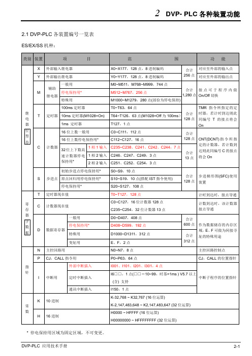
2.1 DVP-PLC各装置编号一览表ES/EX/SS机种:* 停电保持用区域为固定区域,不可变更。
SA/SX/SC机种:*1:非停电保持区域,不可变更。
*2:非停电保持区域,可使用参数设置变更成停电保持区域。
*3:停电保持区域,可使用参数设置变更成非停电保持区域。
*4:停电保持固定区域,不可变更。
SA/SX/SC机种各部装置停电保持设置对照一览表:EH/EH2/SV机种:*1:非停电保持区域,不可变更。
*2:非停电保持区域,可使用参数设置变更成停电保持区域。
*3:停电保持区域,可使用参数设置变更成非停电保持区域。
*4:停电保持固定区域,不可变更。
EH/EH2/SV机种各部装置停电保持设置对照一览表:*1:K-1 表示预设为非停电保持。
⏹在电源On/Off或主机RUN/STOP模式切换时:ES/EX/SS系列机种V5.5版本以上(含)其记忆保持动作如下表所示:SA/SX/SC/EH/EH2/SV系列机种其记忆保持动作如下表所示:2.2 数值、常量 [K] / [H]DVP-PLC 内部依据各种不同控制目的,共使用5种数值类型执行运算的工作,各种数值的任务及功能如下说明。
1.二进制(Binary Number ,BIN )PLC 内部的数值运算或储存均采用二进制,二进制数值及相关术语如下: 位(Bit ): 位为二进制数值的最基本单位,其状态非1即0半字节(Nibble ):是由连续的4个位所组成(如b3~b0)可用来表示一个位数的10进制数字0~9或16进制的0~F字节(Byte ):是由连续的两个半字节所组成(也即8位,b7~b0),可表示16进制的00~FF字(Word ):是由连续的两个字节所组成(也即16位,b15~b0),可表示16进制的4个位数值0000~FFFF双字(Double Word ): 是由连续的两个字所组成(也即32位,b31~b0),可表示16进制的的8个位数值00000000~FFFFFFFF二进制系统中位、半字节、字节、字、及双字的关系如下图所示:NB0NB1NB2NB3NB4NB5NB6NB7BY3BY2BY1BY0W1DWW0双字字字节半字节位b2.八进制(Octal Number ,OCT )DVP-PLC 的外部输入及输出端子编号采八进制编码: 例:外部输入:X0~X7,X10~X17…(装置编号) 外部输出:Y0~Y7,Y10~Y17…(装置编号) 3.十进制(Decimal Number ,DEC )十进制在DVP-PLC 系统应用的时机如下:●作为定时器T、计数器C等的设置值,例:TMR C0 K50。
台达DVP-PLC各装置编号一览表

2.1 DVP-PLC各装置编号一览表ES/EX/SS机种:* 停电保持用区域为固定区域,不可变更。
SA/SX/SC机种:*1:非停电保持区域,不可变更。
*2:非停电保持区域,可使用参数设置变更成停电保持区域。
*3:停电保持区域,可使用参数设置变更成非停电保持区域。
*4:停电保持固定区域,不可变更。
SA/SX/SC机种各部装置停电保持设置对照一览表:EH/EH2/SV机种:*1:非停电保持区域,不可变更。
*2:非停电保持区域,可使用参数设置变更成停电保持区域。
*3:停电保持区域,可使用参数设置变更成非停电保持区域。
*4:停电保持固定区域,不可变更。
EH/EH2/SV机种各部装置停电保持设置对照一览表:*1:K-1 表示预设为非停电保持。
⏹在电源On/Off或主机RUN/STOP模式切换时:ES/EX/SS系列机种V5.5版本以上(含)其记忆保持动作如下表所示:SA/SX/SC/EH/EH2/SV系列机种其记忆保持动作如下表所示:2.2 数值、常量 [K] / [H]DVP-PLC 内部依据各种不同控制目的,共使用5种数值类型执行运算的工作,各种数值的任务及功能如下说明。
1.二进制(Binary Number ,BIN )PLC 内部的数值运算或储存均采用二进制,二进制数值及相关术语如下: 位(Bit ): 位为二进制数值的最基本单位,其状态非1即0半字节(Nibble ):是由连续的4个位所组成(如b3~b0)可用来表示一个位数的10进制数字0~9或16进制的0~F字节(Byte ):是由连续的两个半字节所组成(也即8位,b7~b0),可表示16进制的00~FF字(Word ):是由连续的两个字节所组成(也即16位,b15~b0),可表示16进制的4个位数值0000~FFFF双字(Double Word ): 是由连续的两个字所组成(也即32位,b31~b0),可表示16进制的的8个位数值00000000~FFFFFFFF二进制系统中位、半字节、字节、字、及双字的关系如下图所示:NB0NB1NB2NB3NB4NB5NB6NB7BY3BY2BY1BY0W1DWW0双字字字节半字节位b2. 八进制(Octal Number ,OCT )DVP-PLC 的外部输入及输出端子编号采八进制编码: 例:外部输入:X0~X7,X10~X17…(装置编号) 外部输出:Y0~Y7,Y10~Y17…(装置编号) 3.十进制(Decimal Number ,DEC )十进制在DVP-PLC 系统应用的时机如下:●作为定时器T、计数器C等的设置值,例:TMR C0 K50。
台达PLC各系列的功能说明

台达PLC各系列的功能说明台达PLC主要包括:E系列主机;S系列主机;新增主机PM主机和SV主机。
一,E系列主机包括:EX;ES;EH21,EH2系列:优异的运算功能,内置庞大的程序与资料存储空间,支持超过200个应用指令,新增2轴直线/圆弧插补运动控制功能,并可搭配多样化的高速特殊扩充模块与功能卡,可满足各式各样要求及时反应的应用.1)主机点数:16/20/32/40/48/64/80 2)最大I/O点数:512点3)内存容量:16K Steps 4)运算执行速度:0.24us(基本指令)5)通讯接口:内置RS-232与RS-485,相容MODBUS ASCII/RTU通讯协议,可扩充第3个通讯端口(弹性扩展功能卡;型号:DVP-F232S和DVP-F485S。
6)资料存储器:10,000字节7)档案存储器: 10,000字节该系列应用:1):200khz高速计数器和内置独立200khz脉冲输出功能(提供伺服定位指令)。
PLC机型:DVP20EH00T和DVP32EH00T;DVP40EH00R2/T220/32点主机支持2点200khz(Y0,Y2);40点主机支持2组AB相200khz脉冲输出(Y0,Y1)(Y2,Y3)和2点200khz脉冲输出(Y4,Y6)。
2):可连接8台模拟,温度,定位,计数器等扩展模块PID,PLC Easy Link(32站),有187条应用指令。
3):该系列支持数字,模拟,通讯,内存功能卡与资料设定器等功能。
4):内置4组硬件高速计数器,1):1相1:组数(6)频宽(10Khz)(一般型)2):1相1:组数(2/2)频宽(200khz/20Khz)3):1相2:组数(2/2)频宽(200khz/20Khz)4):2相2:组数(2/2)频宽(200khz/20Khz)5):优异的运算能力:CPU+ASIC双处理器,支持浮点运算。
6):直线/圆弧补间运动功能支持最新开发的直线/圆弧插补运动控制指令,搭配高速脉冲输出功能,可以轻易达到两轴同时动作的控制要求。
台达全系列PLC说明书及应用手册
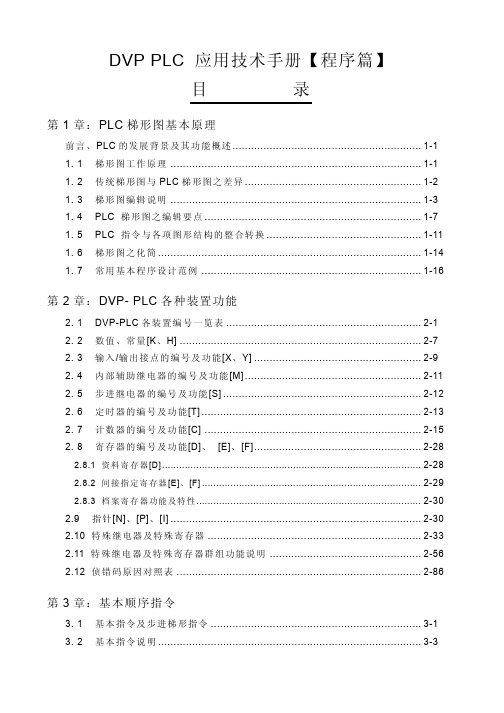
● (API00~09)回路控制 ........................................................................... 6-1 ● (API10~19)传送比较 ........................................................................... 6-17 ● (API20~29)四则逻辑运算 .................................................................... 6-30 ● (API30~39)旋转位移 ........................................................................... 6-42 ● (API40~49)数据处理 ........................................................................... 6-53
第 2 章:DVP- PLC 各种装置功能
2. 1 DVP-PLC 各装置编号一览表 ............................................................... 2-1 2. 2 数值、常量[K、H] .............................................................................. 2-7 2. 3 输入/输出接点的编号及功能[X、Y] ...................................................... 2-9 2. 4 内 部 辅 助 继 电 器 的 编 号 及 功 能 [M] ......................................................... 2-11 2. 5 步进继电器的编号及功能[S] ................................................................ 2-12 2. 6 定时器的编号及功能[T] ....................................................................... 2-13 2. 7 计数器的编号及功能[C] ...................................................................... 2-15 2. 8 寄存器的编号及功能[D]、 [E]、[F]...................................................... 2-28