SF20GG-T中文资料
箱变技术规范
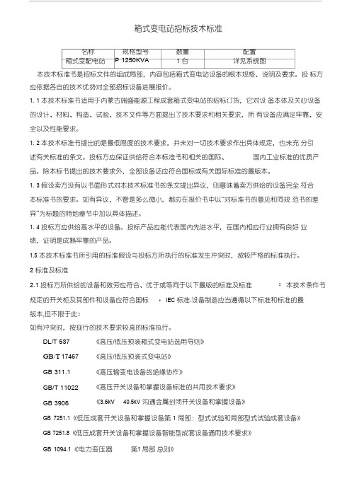
名称箱式变配电站规格型号P 1250KVA数量1 台配置详见系统图箱式变电站招标技术标准本技术标准书是招标文件的组成局部,内容包括箱式变电站设备的根本规格、说明及要求。
投标方应依据各自的技术优势对全部招标设备进展报价。
1. 1 本技术标准书适用于内蒙古瑞盛能源工程成套箱式变电站的招标订货,它对设备本体及关心设备的设计、材料、构造、试验、技术文件等方面提出了技术要求和相关要求,所有设备应满足牢靠、安全以及性能要求。
1. 2 本技术标准书提出的是最低限度的技术要求,并未对一切技术要求作出具体规定,也未充分引述有关标准的条文。
投标方应保证供给符合本标准书和相关的国际、国内工业标准的优质产品。
除本标书提出的技术要求外,全部设备还应符合国标或有关国际标准的最版本。
1. 3 假设卖方没有以书面形式对本技术标准书的条文提出异议,则意味着卖方供给的设备完全符合本标准书的要求。
如有异议,不管是多么微小,都应在报价书中以“对标准书的意见和同规范书的差异”为标题的特地章节中加以具体描述。
1. 4 投标方应供给高水平的设备。
投标产品应能代表国内先进水平,在国内相应行业拥有良好业绩,证明是成熟牢靠的产品。
1.5 本技术标准书所引用的标准假设与投标方所执行的标准发生冲突时,按较严格的标准执行。
2标准及标准2.1投标方所供给的设备和效劳应符合、优于或等同于以下最版的标准及标准:本技术条件书规定的开关柜及其部件和设备应符合国标,IEC 标准.设备制造应当遵循以下标准和标准的最版本,但不限于此:如有冲突时,按现行的技术要求较高的标准执行。
DL/T 537 GB/T 17467 GB 311.1 GB/T 11022 GB 3906《高压/低压预装箱式变电站选用导则》《高压/低压预装式变电站》《高压输变电设备的绝缘协作》《高压开关设备和掌握设备标准的共用技术要求》《3.6kV 40.5kV 沟通金属封闭开关设备和掌握设备》GB 7251.1《低压成套开关设备和掌握设备第1 局部:型式试验和局部型式试验成套设备》GB 7251.8《低压成套开关设备和掌握设备智能型成套设备通用技术要求》GB 1094.1《电力变压器第1局部总则》GB 1904.2《电力变压器第2局部温升》GB 4208《外壳防护等级〔IP 代码〕》专业文档供参考,如有帮助请下载。
标准金属量器20L不锈钢精确度高的详细描述碳钢
标准金属量器20L,不锈钢精确度高的详细描述:/碳钢标准金属量器规格:10L、20L、50L、100L、200L、500L、1000L;材质:不锈钢(1Cr8Ni9Ti);等级:二等标准金属量器适用范围:用于计量液体和气体体积的标准计量器具,是在计量高精度容积时必须配备的一种标准计量装置。
它广泛应用于流量计量仪表的检定装置中,是流量仪表在制造、科研中性能测试的重要设备之一。
1、用途:a.标定标准体积管的容积;b.检定低一级的标准量器及工作量器;c.检定各种油槽车、加油机、啤酒罐等计量容积。
2、特点:a.准确度高;b.采用1Cr18Ni9Ti不锈钢板制造,内壁永不生锈;c.标准量器与介质接触的部分均采用了抛光工艺处理,挂水量少;d.标准量器经过时效处理,无残余应力引起的变形,性能稳定;e.使用和维护方便;f.每台标准量器出厂前,均经过国家计量部门的检定,颁证。
主要技术参数:1、被测介质:水、油(汽油、柴油等)、气体等介质;2、准确度:a.一等标准量器为:5 X 10⁻⁵ ;b.二等标准量器为:2.5 X 10⁻⁴ ;c.三等标准量器为:(0.5--1)X 10-3 。
3、标称容积(L):5、10、20、50、100、200、500、1000、2000;4、介质工作温度:10℃--30℃;5、工作条件:a.环境温度:5℃--40℃;b.相对湿度:5%--95%;c.大气压力:86kPa--106kPa;6、标准工作条件:a.环境温度:20℃;b.相对湿度:65%;c.大气压力:101.325kPa标准金属量器1000L 不锈钢沧州中渤重工机械装备有限公司是专业生产标准金属量器的生产厂家,其中1000L比标准罐或者大于1000L标准罐,我们已经做到了国内领先的生产技术。
提醒给广大用户关于1000L标准罐的基本常识:规格达到1000L的标准罐,使用材质为:不锈钢材质,材质为:碳钢材质,跟大家分享关于标准罐的使用用途:1、标定标准体积管的容积;2、检定低一级的标准量器及工作量器;3、检定各种油槽车、加油机、啤酒罐等计量容积。
金布里特 SF4 红外发射二极管数据手册说明书
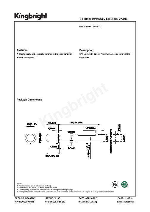
T-1 (3mm) INFRARED EMITTING DIODE 4. The specifications, characteristics and technical data described in the datasheet are subject to change without prior notice.Selection GuideAbsolute Maximum Ratings at TA=25°CElectrical / Optical Characteristics at TA=25°CPart No.Emitting Color (Material)Lens TypePo (mW/sr) [2] @ 20mA *50mA Viewing Angle [1] Min. Typ. 2θ1/2L-34SF4CInfrared (GaAlAs)Water Clear3 16 *5 *2050°Parameter P/N Symbol Typ. Max. Units Test ConditionsForward Voltage [1] SF4 V F 1.3 1.6 VI F =20mAReverse CurrentSF4I R 10 uA V R = 5VCapacitance SF4 C 90 pF V F =0V;f=1MHz Peak Spectral Wavelength SF4λP 880 nm I F =20mASpectral BandwidthSF4 Δλ1/2 50 nmI F =20mAParameter Symbol Values UnitsPower dissipation P D 80 mWDC Forward Current I F 50 mAPeak Forward Current [1] i FS 1.2A Reverse Voltage V R 5V Operating Temperature T A -40 To +85 °C Storage Temperature T STG-40 To +85°CLead Solder Temperature [2] 260°C For 3 Seconds Lead Solder Temperature [3]260°C For 5 SecondsNotes:1. Forward Voltage: + / -0.1V.2. Wavelength value is traceable to CIE127-2007 standards.3. Excess driving current and / or operating temperature higher than recommended conditions may result in severe light degradation or premature failure.Notes:1. θ1/2 is the angle from optical centerline where the luminous intensity is 1/2 of the optical peak value.2. *Radiant intensity with asterisk is measured at 50mA;Radiant Intensity / luminous flux: +/-15%.3. Radiant intensity value is traceable to CIE127-2007 standards.Notes:1. 1/100 Duty Cycle, 10μs Pulse Width.2. 2mm below package base.3. 5mm below package base.4. Relative humidity levels maintained between 40% and 60% in production area are recommended to avoid the build-up of static electricity – Ref JEDEC/JESD625-A and JEDEC/J-STD-033.Ki ng br i g ht。
TDFS型号温度散热流量切换器技术参数手册说明书

The SERIES TDFS on change of flow.to cool. The flow Higher FlowEnsure that the process fluid is compatible with the wetted materials, and do not exceed the maximum device ratings.Ensure that the system is not pressurized before installing or removing this device or other objects from the system. The deviceand/or object may become a projectile.Do not use with abrasive fluid mixtures (The polysulfone may be abraded.)Use caution if fluid temperature changes or fluid composition changes are present in the end application. Verify that the deviceoperates properly if either is present. The setpoint will shift if the specific heat, density or viscosity of the fluid changes.Mount the TDFS so that the sensor extends into the flow by 10-25% of the pipe ID. Use PTFE tape on the process connection to reduce the risk of leaks. For proper flow measurement, the sensor must be fully submerged in the fluid. Bubbles, turbulence, and sediments will cause improper operation. For best operation, mount 30° to 150° off vertical on horizontal runs (See Figure 2). Allow a straight run of at least 12 pipe di-ameters upstream and 5 pipe diameters downstream to ensure optimal flow measure-ment. For optimal repeatability, ensure the flow switch is not operating in the transition region (laminar to turbulent flow).ELECTRICAL CONNECTIONThe power input and switched outputs are individually fused at 0.5A and are reverse polarity protected. A shielded 4 conductor cable provides the electrical connection to the TDFS. The cable drain wire must be connected to earth ground in CE applications or when strong RF fields are present.Two open collector switched outputs are provided. One is normally open (NO), and the other output is normally closed (NC). The output logic is shown in Table 1.SETPOINT ADJUSTMENTThe setpoint may be adjusted with the supplied magnet. There are two setpoint targets on the unit located under the LED status indicator on opposite sides of the unit (see Figure 4). Either setpoint target may be used, and either end of the magnet may be used. If the setpoint does not set easily, try reversing the magnet.Steps:1) Ensure that the unit is properly installed and powered.2) Set the system flow to the desired setpoint flow rate.3) Tap the setpoint target three times with the supplied magnet. Move the magnet approximately 2 inches away from the target between each tap. The taps should be approximately 1 second apart. The LED status indicator will blink slowly when the setpoint request is recognized. The slow blink will stop when the setpoint has been stored.©Copyright 2017 Dwyer Instruments, Inc.Printed in U.S.A. 5/17FR# 443813-00 Rev. 4STATUS INDICATORThe status indicator (See Figure 4) provides visual indication of the TDFS status. Two status indicators are located on opposite sides of the unit. Each status indicator has one red LED and one green LED. Table 2 describes the status indicator states.If an error condition is present, the unit will continue measurement attempts until the problem has cleared. The status indicator will cycle on and off during this time.AGENCY APPROVALS AND TEST STANDARDS CE: CENELEC EN 55011: 2006 CENELEC EN 61326-1: 2006 IEC 61000-4-2: 2008 IEC 61000-4-3: 2006 IEC 61000-4-4: 2004 IEC 61000-4-5: 2005 IEC 61000-4-6: 2006 CENELEC EN 55022: 2006 FCC PART 15 CFR TITLE 47: 2008 ICES-003: 2004 Digital Apparatus (Industry Canada) ANSI C63.4-2003 2004/108/EC EMC DIRECTIVEMAINTENANCE/REPAIRUpon final installation of the Series TDFS, no routine maintenance is required. The Series TDFS is not field serviceable and should be returned if repair is needed. Field repair should not be attempted and may void warranty.WARRANTY/RETURNRefer to “Terms and Conditions of Sales” in our catalog and on our website. Contact customer service to receive a Return Goods Authorization number before shipping the product back for repair. Be sure to include a brief description of the problem plus any additional application notes.PARTSIf the magnet is lost another can be ordered from Dwyer with part number 100571-00.Figure 2: Mounting OrientationFigure 3: Wiring DiagramFigure 4: Set Point TargetDC SUPPLY 9-24 VDCSTATUS INDICATORSETPOINT TARGETTable 2: Status Indicator StatesDesign a fail-safe system that takes into consideration the possibility of switch failure, power failure and operator error.。
变压器型号含义大全

变压器型号的含义:第一个字母:O表示为自耦;第二个字母表示相数:S为三相,D为单相;第三个字母:表示冷却方式,F为油浸风冷;J油浸自冷;P强迫油循环;第四个字母:表示绕组数,双绕组不标;S为三绕组;F为分裂绕组;第五个字母:表示导线材料L为铝线,铜线不标;第六个字母:表示调压方式Z有载,无载不标;数字部分:第一个表示变压器容量,第二个表示变压器使用电压等级.根据的SJ-560/10,应该是3相油浸自冷容量为560KVA电压为10KV的变压器一、SII-M-220KV AS11-变压器型号,11为设计序号,节能型产品。
M-全密封。
220kVA-表示额定容量为220千伏安叠铁心无励磁调压油浸配电变压器,220KV A二、scr9-500/10,s11-m-100/10S--三相C--浇注成型(干式变压器)9(11)--设计序号500(100)--容量(KVA)10--额定电压(KV)m--密闭r没查着三、电力变压器型号定义变压器型号通常由表示相数、冷却方式、调压方式、绕组线芯等材料符号,以及变压器容量、额定电压、绕组连接方式组成。
请问下列电力变压器型号代号含义是什么?D S J L Z SC SG JMB YD BK(C) DDGD-单相S-三相J-油浸自冷L-绕组为铝线Z-又载调压SC-三相环氧树脂浇注SG-三相干式自冷JMB-局部照明变压器YD-试验用单相变压器BF(C) -控制变压器(C为C型铁芯结构DDG-单相干式低压大电流变压器四、SFSZ9-31500/110S:三相F:风冷S:三绕组Z:有载调压9:设计序号9型31500:容量为31500kVA110:一次侧额定电压110kV变压器型号含义干式变压器;例如,(SCB10-1000KVA/10KV/0.4KV):S的意思表示此变压器为三相变压器,如果S换成D则表示此变压器为单相。
C的意思表示此变压器的绕组为树脂浇注成形固体。
B的意思是箔式绕组,如果是R则表示为缠绕式绕组,如果是L则表示为铝绕组,如果是Z则表示为有载调压(铜不标)。
80 G3VM-202J1 MOS FET 传感器传输器窄,2.1 mm 高 MOS FET 传感器

G3VM-202J1MOS FET RelaysSlim, 2.1-mm High MOS FET Relays with Miniature, Flat, 8-pin SOP Package.•New models with 2 channels and an 8-pin SOP package now available in the 200-V load voltage series. •Continuous load current of 200 mA.•Dielectric strength of 1,500 Vrms between I/ORoHS compliant!■Application Examples•Broadband systems •Measurement devices •Data loggers•Amusement machinesNote:The actual product is marked differently from the image shown here.■List of Models■DimensionsNote:All units are in millimeters unless otherwise indicated.■Terminal Arrangement/Internal Connections (Top View)■Contact form Terminals Load voltage (peak value)Model Number per stick Number per tape DPST-NOSurface-mounting terminals200 VACG3VM-202J150---G3VM-202J1(TR)---2,500G3VM-202J1Note:The actual product is marked differentlyfrom the image shown here.Weight: 0.2 gG3VM-202J1G3VM-202J1G3VM-202J1G3VM-202J1■Absolute Maximum Ratings (Ta = 25°C)■Electrical Characteristics (Ta = 25°C)■Recommended Operating ConditionsUse the G3VM under the following conditions so that the Relay will operate properly.■Engineering DataLoad Current vs. Ambient TemperatureG3VM-202J1■Safety PrecautionsRefer to “Common Precautions” for all G3VM models.ItemSymbol Rating Unit Measurement ConditionsInputLED forward currentI F 50mARepetitive peak LED forward currentI FP1A 100 µs pulses, 100 pps LED forward current reduction rate∆ I F /°C −0.5mA/°C Ta ≥ 25°CLED reverse voltage V R 5V Connection temperatureT j 125°C OutputOutput dielectric strength V OFF 200V Continuous load current I O 200mA ON current reduction rate∆ I ON /°C −2.0mA/°C Ta ≥ 25°C Dielectric strength between input and output (See note 1.)V I-O 1,500Vrms AC for 1 minOperating temperature T a −40 to +85°C With no icing or condensation Storage temperature T stg −55 to +125°CWith no icing or condensation Soldering temperature (10 s)---260°C10 sNote:1.The dielectric strength between the input andoutput was checked by applying voltage be-tween all pins as a group on the LED side and all pins as a group on the light-receiving side.ItemSymbol Mini-mum Typical Maxi-mum UnitMeasurement conditions InputLED forward voltage V F 1.0 1.15 1.3V I F = 10 mA Reverse currentI R ------10µA V R = 5 V Capacity between terminals C T ---30---pF V = 0, f = 1 MHz Trigger LED forward currentI FT ---13mA I O = 200 mA OutputMaximum resistance with output ON R ON ---58ΩI F = 5 mA, I O = 200 mA Current leakage when the relay is openI LEAK ------ 1.0µA V OFF = 200 V Capacity between I/O terminals C I-O ---0.8---pF f = 1 MHz, Vs = 0 V Insulation resistance R I-O 1,000------M ΩV I-O = 500 VDC, RoH ≤ 60%Turn-ON time tON ---0.6 1.5ms I F = 5 mA, R L = 200 Ω, V DD = 20 V (See note 2.)Turn-OFF timetOFF---0.11ms Note:2.Turn-ON and Turn-OFFTimesItemSymbol MinimumTypicalMaximum UnitOutput dielectric strength V DD---150200V Operating LED forward current I F 57.525mA Continuous load current I O ------130mA Operating temperatureT a− 20 ---65°CCommon Precautions!WARNINGBe sure to turn OFF the power when wiring the Relay, other-wise an electric shock may be received.!WARNINGDo not touch the charged terminals of the SSR, otherwise an electric shock may be received.!CautionDo not apply overvoltage or overcurrent to the I/O circuits of the SSR, otherwise the SSR may malfunction or burn.!CautionBe sure to wire and solder the Relay under the proper soldering conditions, otherwise the Relay in operation may generate ex-cessive heat and the Relay may burn.Typical Relay Driving Circuit ExamplesUse the following formula to obtain the LED current limiting resis-tance value to assure that the relay operates accurately.Use the following formula to obtain the LED forward voltage value to assure that the relay releases accurately.Protection from Surge Voltage on the Input TerminalsIf any reversed surge voltage is imposed on the input terminals, insert a diode in parallel to the input terminals as shown in the fol-lowing circuit diagram and do not impose a reversed voltage value of 3V or more.Surge Voltage Protection Circuit ExampleProtection from Spike Voltage on the Output TerminalsIf a spike voltage exceeding the absolute maximum rated value isgenerated between the output terminals, insert a C-R snubber or clamping diode in parallel to the load as shown in the following circuit diagram to limit the spike voltage.Spike Voltage Protection Circuit ExampleUnused Terminals (6-pin models only)Terminal 3 is connected to the internal circuit. Do not connect anything to terminal 3 externally.Pin Strength for Automatic Mountingn order to maintain the characteristics of the relay, the force imposed on any pin of the relay for automatic mounting must not exceed the following.In direction A: 1.96 NIn direction B: 1.96 NLoadTransistor10 to 100 kΩLoadR1 =V CC− V OL− V F (ON) 5 to 20 mAV F (OFF) = V CC− V OH < 0.8 VLoad ConnectionDo not short-circuit the input and output terminals while the relay is operating or the relay may malfunction.Solder MountingPerform solder mounting under the following recommended con-ditions to prevent the temperature of the Relays from rising.<Flow Soldering>Through-hole Mounting (Once Only)Note:We recommend that the suitability of solder mounting be verified under actual conditions.<Reflow Soldering>Surface Mounting DIP or SOP Packages (Twice Max.) Surface Mounting SSOP Packages (Twice Max.)Note: 1.We recommend that the suitability of solder mounting be verified under actual conditions.2.Tape cut SSOPs are packaged without humidity resis-tance. Use manual soldering to mount them.Manual Soldering (Once Only)Manually solder at 350°C for 3 s or less or at 260°C for 10 s or less.SSOP Handling Precautions<Humidity-resistant Packaging>Component packages can crack if surface-mounted components that have absorbed moisture are subjected to thermal stress when mounting. To prevent this, observe the following precau-tions.1.Unopened components can be stored in the packaging at 5to 30°C and a humidity of 90% max., but they should be used within 12 months.2.After the packaging has been opened, components can bestored at 5 to 30°C and a humidity of 60% max., but they should be mounted within 168 hours.3.If, after opening the packaging, the humidity indicator turnspink to the 30% mark or the expiration data is exceeded, bake the components while they are still on the taping reel, and use them within 72 hours. Do not bake the same com-ponents more than once.Baking conditions: 60±5°C, 64 to 72 hExpiration date: 12 months from the seal date(given on the label)4. f the same components are baked repeatedly, the tapedetachment strength will change, causing problems when mounting. When mounting using dehumidifying measures, always take countermeasures against component damage from static electricity.5.Do not throw or drop components. If the laminated packag-ing material is damaged, airtightness will be lost.6.Tape cut SSOPs are packaged without humidity resistance.Use manual soldering to mount them.AC ConnectionDC Single Connection DC Parallel Connection LoadLoadLoadLoadSolder type Preheating SolderingLead solderSnPb150°C60 to 120 s230 to 260°C10 s max.Lead-free solderSnAgCu150°C60 to 120 s245 to 260°C10 s max.Solder type Preheating SolderingLead solderSnPb140→160°C60 to 120 s210°C30 s max.Peak240°C max.Lead-free solderSnAgCu180→190°C60 to 120 s230°C30 to 50 sPeak260°C max.Solder type Preheating SolderingLead solderSnPb140→160°C60 to 120 s210°C30 s max.Peak240°C max.Lead-free solderSnAgCu150→180°C120 s max.230°C30 s max.Peak250°C max.。
gg20材质标准

GG20材质标准是指一种常见的灰铸铁材质,广泛应用于机械制造、汽车零部件、管道工程等领域。
GG20材质标准的制定对于保障产品质量、促进行业发展具有重要意义。
本文将从GG20材质的化学成分、力学性能、加工工艺以及应用领域等方面进行详细介绍,以期对GG20材质标准有一个全面的了解。
1. 化学成分GG20材质的化学成分是其性能的重要基础。
按照相关标准,GG20材质的化学成分主要包括碳含量、硅含量、锰含量、磷含量和硫含量。
其中,碳含量决定了灰铸铁的硬度和耐磨性,硅含量对于铸件的流动性和收缩性具有重要影响,而锰、磷、硫等元素则会对铸件的性能产生一定影响。
合理控制化学成分可以确保GG20材质具有良好的机械性能和加工性能。
2. 力学性能GG20材质的力学性能是衡量其质量优劣的重要指标之一。
力学性能主要包括抗拉强度、屈服强度、延伸率和冲击韧性等参数。
通过对这些参数的测试和分析,可以评估GG20材质在不同工况下的使用性能,确保其满足相关标准的要求。
合理设计合金配比和熔炼工艺可以有效提高灰铸铁的力学性能,满足不同领域的需求。
3. 加工工艺GG20材质在使用过程中需要经历多道加工工艺,因此其加工性能直接影响着产品的成型质量和加工效率。
灰铸铁具有较好的切削加工性能和磨削加工性能,但同时也存在易产生切屑和切削热的缺点。
针对这些特点,需要采取合适的切削参数和冷却方式,以确保加工效果和加工质量。
此外,还需要注意铸件的收缩余量和变形规律,合理安排浇注系统和浇注工艺,避免产生缺陷。
4. 应用领域GG20材质由于其优良的综合性能,在机械制造、汽车零部件、管道工程等领域得到广泛应用。
例如,在机床床身、汽车发动机缸体、液压管道等方面都可以看到GG20材质的身影。
其良好的耐磨性、耐热性和减振性能,使其成为许多重要零部件的首选材料。
通过严格执行相关标准,可以保证GG20材质在各个领域发挥稳定可靠的作用。
总结起来,GG20材质标准的制定和执行对于推动相关行业的发展和产品质量的提升具有积极的意义。
变压器技术参数
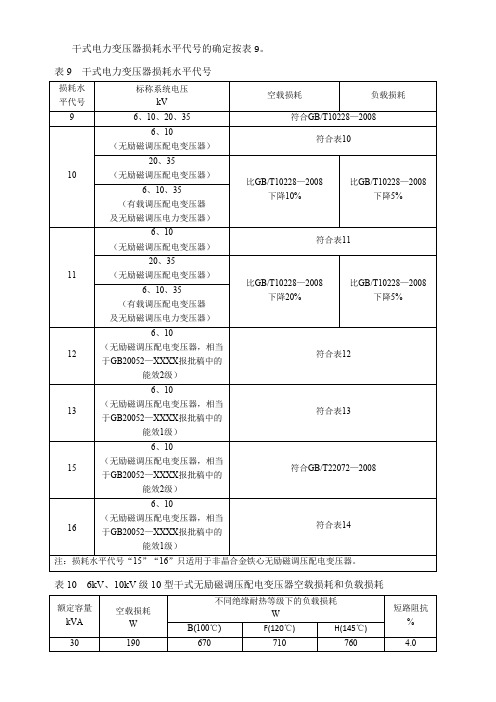
干式电力变压器损耗水平代号的确定按表9。
表9干式电力变压器损耗水平代号表106kV、10kV级10型干式无励磁调压配电变压器空载损耗和负载损耗南阳市瑞光变压器有限公司10kV三相干式变压器技术协议2016年4月1、总则1.2本协议书提出的是最低限度的技术要求,并未对一切技术细节作出规定,也为充分引述有关标准和协议的条文,我方的制造标准以现行国家标准及两部共同的有关条件作为依据。
1.3本协议书所使用的标准如遇我方所执行的标准不一致时,按较高标准执行。
1.4如果我方没有以书面形式对本协议书的条文提出异议,这意味着我方提供的设备完全符合本协议书的要求。
1.5本协议书经供需双方确认作为订货合同的技术附件,包括投标书及澄清文件与合同正文具有同等的法律效力。
1.6遵循的标准GB1094.1—2013《总则》GB1094.2---2013电力变压器第2部分温升GB1094.3—2003电力变压器第3部分绝缘水平GB1094.5-2008电力变压器第5部分承受短路的能力GB1094.11—2007《干式电力变压器》GB/T10228—2008《干式电力变压器技术参数和要求》GB/T17211—1998《干式电力变压器负载导则》GB/T17468—1998《电力变压器选用导则》CECS115:2000《干式电力变压器选用、验收维护规程》GB/T7354局部放电测量JB/T10088-2004《6—500KV级变压器声级》JB/Y3837—2010《变压器类产品型号编制办法》2、使用环境条件2.1最高环境温度+40℃2.2最低环境温度—40℃2.3最大日温差25K2.4户内相对湿度:日平均值≤95%月平均值≤90%2.5耐地震能力地面水平加速度0.2g;垂直加速度0.1g同时作用。
采用共振、正弦、拍波试验方法;激振5次,每次5波,每次间隔2s。
安全系数不小于1.67。
2.6系统额定频率:50Hz2.7安装位置:户内2.8外绝缘爬电比距:户内≥20mm/KV3、供货范围三相环氧树脂浇注绝缘干式变压器4、技术要求4.1.1产品性能参数4.1.2产品型号:SCB10—1600/10,4.1.3系统标称电压:10KV4.1.4最高运行电压:12KV4.1.5额定频率:50Hz4.1.6相数:3相4.1.7接线组别:D,yn114.1.8短路阻抗:Ud=6%(误差不大于±10%)4.2绝缘水平:4.2.1线圈绝缘水平4.2.2绝缘介质及耐热等级:全绝缘F级4.2.3冷却方式:空气自冷,AN4.2.4不对称要求:无4.2.5变压器配备温度控制装置,具备温度超限报警功能及跳闸功能;这些装置并应符合它们各自的技术标准。
- 1、下载文档前请自行甄别文档内容的完整性,平台不提供额外的编辑、内容补充、找答案等附加服务。
- 2、"仅部分预览"的文档,不可在线预览部分如存在完整性等问题,可反馈申请退款(可完整预览的文档不适用该条件!)。
- 3、如文档侵犯您的权益,请联系客服反馈,我们会尽快为您处理(人工客服工作时间:9:00-18:30)。
e 3SF20AG - SF20JG
2.0A SUPER-FAST GLASS PASSIVATED RECTIFIER
Features
Maximum Ratings and Electrical Characteristics
@ T A = 25°C unless otherwise specified
·Glass Passivated Die Construction ·Super-Fast Switching for High Efficiency ·Surge Overload Rating to 60A Peak ·Low Reverse Leakage Current
·
Lead Free Finish, RoHS Compliant (Note 4)
Mechanical Data
·Case: DO-15
·Case Material: Molded Plastic. UL Flammability Classification Rating 94V-0
·Moisture Sensitivity: Level 1 per J-STD-020C ·Terminals: Finish – Tin. Solderable per MIL-STD-202,Method 208 ·Polarity: Cathode Band ·Marking: Type Number
·Ordering Information: See Page 3·
Weight: 0.35 grams (approximate)
Single phase, half wave, 60Hz, resistive or inductive load. For capacitive load, derate current by 20%.
Notes: 1. Valid provided that leads are kept at ambient temperature at a distance of 9.5mm from the case. 2. Measured with I F = 0.5A, I R = 1.0A, I rr = 0.25A. See Figure 5. 3. Measured at 1.0MHz and applied reverse voltage of 4.0V DC.
4. RoHS revision 13.2.2003. Glass and high temperature solder exemptions applied, see EU Directive Annex Notes 5 and 7.
5. Short duration pulse test used to minimize self-heating effect.
00.4
0.8
1.2
1.6
2.025
50
75
100
125
150
175
200
I , A V E R A G E F O R W A R D R E C T I F I E D (A V )C U R R E N T (A )
T , AMBIENT TEMPERATURE (°C)A
Fig. 1 Forward Current Derating Curve
0.01
0.1
1.0
10
0.6
0.8
1.0
1.2
1.4
I , I N S T A N T A N E O U S F O R W A R D C U R R E N T (A )
F V , INSTANTANEOUS FORWARD VOLTAGE (V)
F Fig. 2 Typical Forward Characteristics
1
10
1001
10
100
C , T O T A L C A P A C I T A N C E (p F )
T V , DC REVERSE VOLTAGE (V)R Fig. 4 Typical T
otal Capacitance
50V DC Approx
Oscilloscope (Note 1)
Pulse Generator (Note 2)
Device Under Test
t rr
Set time base for 50/100 ns/cm
+0.5A
0A -0.25A
-1.0A
Fig. 5 Reverse Recovery Time Characteristic and Test Circuit
(+)
(+)
(-)(-)
I , P E A K F O R W A R D S U R G E C U R R E N T (A )
F S M 020
40
60
1
10
100
NUMBER OF CYCLES AT 60 Hz Fig. 3 Peak Forward Surge Current
Notes:
6.For packaging details, visit our website at /datasheets/ap02008.pdf.
(Note 6)
Ordering Information
IMPORTANT NOTICE
Diodes Incorporated and its subsidiaries reserve the right to make modifications, enhancements, improvements, corrections or other changes without further notice to any product herein. Diodes Incorporated does not assume any liability arising out of the application or use of any product described herein; neither does it convey any license under its patent rights, nor the rights of others. The user of products in such applications shall assume all risks of such use and will agree to hold Diodes Incorporated and all the companies whose products are represented on our website, harmless against all damages.
LIFE SUPPORT
Diodes Incorporated products are not authorized for use as critical components in life support devices or systems without the expressed written approval of the President of Diodes Incorporated.。