8ETL06FPPBF;8ETL06;8ETL06FP;中文规格书,Datasheet资料
ssd1306双色中文
Ver:A
修正完成 20130326 20130522
i
金晨电子
Ver:A
内容
修正历史................................................................................................................................i 内容..................................................................................................................................... ii~iii 11.. 基本功能...............................................................................................................1~6
金晨电子
刘玉汉化,本人不会英文,以下翻译主要有谷歌翻译提供
金晨电子
产品名称: 产品ID:
OEL 显示模块
顾客:
批准
来自: 金晨电子
批准
金晨电子
修正历史
零件号码 UG-2864TMBEG01
修正 A B
内容
New
R 变更为 R IRE)参数 0XCF 变更为 0X66
1.1 显示规格 ................................................................................................................. 1 1.2 机械规格............................................................................................................ 1 1.3 有效面积 / 内存映射 & 像素结构...................................................................... 1 1.4 机械图纸.................................................................................................................... 2 1.5 引脚定义 ............................................................................................................................. 3 1.6 方框图............................................................................................................................ 5
Sugatsune 玻璃支持硬件及配件说明书

SHELF & SUPPORT HARDWAREGLASS CLAMPSGLASS SHELF SUPPORTSSOAP HOLDERSBRACKETSMIRROR SUPPORTSGLASS STANDOFFSSHELF STANDARDS & ACCESSORIESSHELVING SYSTEMSMIRROR SUPPORTS PictureSMB-15RSPM-20BSP-1820(HEAVY DUTY)SPN-1820(NARROW PROFILE)496SPE-FB20S330lbs/4pcsSPHL-25SPN-15FSL-MBFSL-LSPN-17ECSPH-20SPH-5286lbs/4pcsSPH-1511lbs/pc SPB-35220lbs/4pcs 99lbs/4pcs 176lbs/4pcsSPF-20SPB-15R SPB-20SPW-20Item No.Glass Thickness (mm)Weight (g)Box (pcs)Carton (pcs) 9303VA21032410100Material Finish 316 Stainless Steel SatinItem No.Glass Thickness (mm)Weight (g)Box (pcs)Carton (pcs) 9344VA21022910100Material Finish316 Stainless Steel Satin • 316 stainless steel clamp.• F or flat surface.• O ptional Parts: 4820VA (Safety Pin)• S ee page 466 for load capacity.• T empered Glass Recommended.• 316 stainless steel clamp.• F or flat surface.• O ptional Parts: 9320VA (Safety Pin)4849VA (Safety Plate)• S ee page 466 for load capacity.• T empered Glass Recommended.GLASS CLAMP9303VA2 GLASS CLAMP9344VA2ZN1ZN1ZN5Item No.4846ZN14846ZN5GLASS CLAMPZN1ZN1ZN1 ZN54846ZN5 (P.463)Item No.Glass Thickness (mm)2878ST86~10MOUNTING SCREWMS7 MS15ZN1ZN5ZN1ZN5ZN1Item No.D LDSP-S/1212 (15/32")120 ( 4-45/64" ) DSP-S/1512 (15/32")150 ( 5-57/64" ) DSP-S/2012 (15/32")200 ( 7-55/64" ) DSP-M/1514 (35/64")150 ( 5-57/64" ) DSP-M/2014 (35/64")200 ( 7-55/64" ) DSP-M/2414 (35/64")240 ( 9-7/16" ) DSP-M/3014 (35/64")300 (11-51/64") DSP-L/2020 (25/32")200 ( 7-55/64" ) DSP-L/2520 (25/32")250 ( 9-53/64" )SU-B80/MSU-B65/MSU-B50/MXL-SA01-120/SXL-SA01-150/SXL-SA01-180/SXL-SA01-240/SStainless Steel WhiteBlackApplication ExampleEBDFolding BracketDamper unit477.21-3/16"(30 mm)12-1/2" (317 mm)P1*6-3/4" (171 m m )1/16"(2 m m )15/16"(24 m m )2-5/8"(67 m m )1-3/4"(45 m m )1-1/2"(38 m m )6-1/8" (156 mm)3-7/8"(98 mm)1-7/16"(36 mm)1-7/16"(36 m m )FOLDING BRACKET WITH SOFT-CLOSETo find your Min./Max. table weight per single damper, please reference the formula shown next to the charts above and 18” depth examples below.EB-303/EP-DMaximum weight 7.2 lbs = 130/18 in.Minimum weight 2.8 lbs = 52/18 in.EB-317/EP-DMaximum weight 19.1 lbs = 345/18 in.Minimum weight 12.5 lbs = 225/18 in.Stainless SteelBlackTT EB-317/EP-D• A utomatically locks when flap is in open position.• P ress lever to release the lock.• A dditional hinges not required.• D amper unit with a soft-closing feature which makes bracket smoother and safer.• R efer to DAMPER WEIGHT CHART below for appropriate table weight and depth when softly folding down the table. • F or panel thickness 9/16" ~ 1-3/8" (15 ~ 35 mm).• D urability tested 50,000 cycles (private).Side Levers Connecting RodSafety Lock ScrewHolding BracketSpringConnecting LeverFor EB-2000-3 onlyNo.Part Name Material Finish1Connecting LeverAluminum AnodizedAluminum 2Side Lever3Spring Stainless Steel4Washer Plastic5Holding BracketAluminum AnodizedAluminum 6Connecting RodStainless Steel477.4Item No.Rod QtyRod Length (L)Side Lever QtySafety Lock QtyHolding Bracket QtySpring QtyEB-1000-2139-3/8" (1000 mm)2131EB-1500-2159-1/16" (1500 mm)2131Item No.Rod QtyRod Length (L)Side Lever QtyConnecting Lever QtySafety Lock Qty Holding Bracket Qty Spring QtyEB-2000-3239-3/8" (1000 mm) each 21161Connecting LeverLEVER RELEASE FOR EB SERIES FOLDING BRACKETSLEVER RELEASE for EB Folding Bracket LEVER RELEASE for EB Folding Bracket EB-1000-2/1500-2EB-2000-3SHELF & SUPPORT HARDWARERecommended Hinge: 388H38830-25-DDamper388HDo not lift up the shelf forcibly. It may result in breakage.Z058* S pecial wrench Z058 required for installation. (Sold Separately)Cut Out DimensionCut Out DimensionMaterialFinish 302 Stainless Steel/Aluminum SatinItem No.Glass Thickness (mm)Weight (g)Box (pcs)Carton (pcs)7005VA 8~12192440MaterialFinish 302 Stainless Steel/Aluminum SatinItem No.Glass Thickness (mm)Weight (g)Box (pcs)Carton (pcs)7000VA 8~12167440Z058• F lush mount type glass standoff.• R ecommended Screw Size: M8 bolt • L onger base 80~180 mm (3-5/32"~7-3/32") available as special order.• R ecommended for use with tempered glass.* S pecial wrench Z058 required for installation. (Sold Separately)• G lass standoff with round face plate.• R ecommended Screw Size: M8 bolt • L onger base 80~180 mm (3-5/32"~7-3/32") as special order.• R ecommended for use with tempered glass.GLASS STANDOFF 7000VAGLASS STANDOFF 7005VAItem No.Glass Thickness (mm) Item No.Glass Thickness (mm) 7015VA8~12Item No.Glass Thickness (mm)7061VA6~12GLASS STANDOFF Item No.Glass Thickness (mm)7062VA6~12Z057* S pecial wrench Z057 required for installation. (Sold Separately)Item No.Glass Thickness (mm)7083VA 6~12Finish GLASS STANDOFFItem No.Glass Thickness (mm)7120VA8GLASS STANDOFFSMB-15RSPM-20BSP-1820(HEAVY DUTY)SPN-1820(NARROW PROFILE)496SPE-FB20S330lbs/4pcsSPHL-25SPN-15FSL-MBFSL-LSPN-17ECSPH-20SPH-5286lbs/4pcsSPH-1511lbs/pc SPB-35220lbs/4pcs 99lbs/4pcs 176lbs/4pcsSPF-20SPB-15R SPB-20SPW-20Item No.Item No.Load Capacity (kg)SPH-15130 (286 lbs)/4 pcs END CAPWeight (g)1.3StandardAP-DM1820WT AP-DM1820AP-DH1820Item No.D E Weight (g)AP-DM1820178017113 AP-DM1820WT AP-DM1820BL AP-DM2600250047161 AP-DH1820178017131 AP-DH2600250047187Item No.Screw TypeAP-SC3-16 AP-SC3-16WT AP-SC3-16BL AP-SC3-30 AP-SC3-30WT AP-SC3-30BL • A luminum shelf standard.• E asy to cut to desired length.• T hin profile (3 mm, 1/8") suitable for surface mount.• S crew hole located every 120 mm (4-23/32").• N ew slot shape to prevent shelf support from falling off.• S pecial screw with silver finish available. (AP-SC3-16)• S crews and accessories sold separately.• A luminum shelf standard.• E asy to cut to desired length.• D esigned for press-fit mount without using screws.• N ew slot shape to prevent shelf support from falling off.• S crews and accessories sold separately.* Install the standard with concave slot(located every 120 mm) pointing upward.* Fit tightness may vary depending on the panel/wall material. Use adhesive if loose.Bore Dimension (In case of Plywood)SHELF STANDARDHolds in any height。
Sun StorageTek Dual 4 Gb FC Dual GbE HBA (Emulex)

Sun StorageT ek™ Dual 4 Gb FC Dual GbE HBA (Emulex) 安装指南适用于 HBA 型号 SG-XPCIE2FCGBE-E-Z Sun Microsystems, Inc.文件号码 820-5520-102008 年 7 月,修订版 A请将有关本文档的意见和建议提交至:/hwdocs/feedback版权所有 © 2008 Sun Microsystems, Inc., 4150 Network Circle, Santa Clara, California 95054, U.S.A. 保留所有权利。
美国政府权利-商业软件。
政府用户应遵循 Sun Microsystems, Inc. 的标准许可协议,以及 FAR(Federal Acquisition Regulations,即“联邦政府采购法规”)的适用条款及其补充条款。
必须依据许可证条款使用。
本发行版可能包含由第三方开发的内容。
本产品的某些部分可能是从 Berkeley BSD 系统衍生出来的,并获得了加利福尼亚大学的许可。
UNIX 是 X/Open Company, Ltd. 在美国和其他国家/地区独家许可的注册商标。
Sun、Sun Microsystems、Sun 徽标、Netra、Solaris、Sun Ray、Sun StorEdge、Sun StorageTek、UNIX、Sun Blade、SunVTS 和 SunSolve 是 Sun Microsystems, Inc. 及其子公司在美国和其他国家/地区的商标或注册商标。
所有 SPARC 商标的使用均已获得许可,它们是 SPARC International, Inc. 在美国和其他国家/地区的商标或注册商标。
标有 SPARC 商标的产品均基于由 Sun Microsystems, Inc. 开发的体系结构。
ExpressModule™。
56-VBA-SMX83EN 产品说明书

Instruction ManualBooster Regulator56 – VBA SeriesII 3 GD56-VBA10A56-VBA11A56-VBA20A56-VBA22A56-VBA40A56-VBA42A56-VBA43AEX h IIB T6 Gc2o C≤Ta≤50o CEx h IIIB T71°C DcThe intended use of this ATEX Category 3 Booster Regulator is to convertthe potential energy provided by compressed air into a force whichcauses mechanical linear motion. The mechanical linear motion is thenused to increase the pressure of the compressed air.Certifcate Number:SMC. 19.0046 XNote 1: The X at the end of the certificate number represents that this product issubject to “Special Conditions of Use”, please see Section 2.2.ATEX Marking DescriptionSpecific Marking for Explosion ProtectionII Equipment Group3 Equipment CategoryGD Environment (Gas/Dust)Ex h General Protection Level SymbolsIIB Gas Sub-divisionIIIC Dust Sub-divisionT Temperature ClassificationGc/Dc Equipment Protection LevelTa Ambient Temperature Range1 Safety InstructionsThese safety instructions are intended to prevent hazardous situationsand/or equipment damage. These instructions indicate the level ofpotential hazard with the labels of “Caution,” “Warning” or “Danger.”They are all important notes for safety and must be followed in addition toInternational Standards (ISO/IEC) *1), and other safety regulations.*1) ISO 4414: Pneumatic fluid power - General rules relating to systems.ISO 4413: Hydraulic fluid power - General rules relating to systems.IEC 60204-1: Safety of machinery - Electrical equipment of machines.(Part 1: General requirements)ISO 10218-1: Manipulating industrial robots -Safety. etc.∙Refer to product catalogue, Operation Manual and HandlingPrecautions for SMC Products for additional information.∙Keep this manual in a safe place for future reference.CautionCAUTION indicates a hazard with a low level of risk, whichif not avoided, could result in minor or moderate injury.WarningWARNING indicates a hazard with a medium level of risk,which if not avoided, could result in death or serious injury.DangerDANGER indicates a hazard with a high level of risk,which if not avoided, will result in death or serious injury.1 Safety Instructions (continue)∙Always ensure compliance with relevant safety laws andstandards.∙All work must be carried out in a safe manner by a qualified person incompliance with applicable national regulations.∙The compatibility of pneumatic equipment is the responsibility of theperson who designs the pneumatic system or decides its specifications.∙Since the products specified here can be used in various operatingconditions, their compatibility with the specific pneumatic system mustbe based on specifications or after analysis and/or tests to meetspecific requirements.∙Compressed air can be dangerous if an operator is unfamiliar with it.Trained and experienced personnel should perform assembly, handlingor repair of pneumatic systems.∙Do not service machinery/equipment or attempt to remove componentsuntil safety is confirmed.∙Inspection and maintenance of machinery/equipment should only beperformed after confirmation of safe locked-out control positions.∙When equipment is to be removed, confirm the safety process asmentioned above. Switch off air and electrical supplies and exhaust allresidual compressed air in the system.∙Before machinery/equipment is re-started, ensure all safety measuresto prevent sudden movement of cylinders etc. (Supply air into thesystem gradually to create back pressure, i.e. incorporate a soft-startvalve).∙Do not use this product outside of the specifications. Contact SMC if itis to be used in any of the following conditions:a) Conditions and environments beyond the given specifications, or if theproduct is to be used outdoors.b) Installations in conjunction with atomic energy, railway, air navigation,vehicles, medical equipment, food and beverage, recreation equipment,emergency stop circuits, press applications, space, military or safetyequipment.c) An application, which has the possibility of having negative effects onpeople, property, or animals, requiring special safety analysis.Quality of air source:∙Connect a mist separator to the inlet side near the booster regular. Ifthe quality of the compressed air is not thoroughly controlled, thebooster regulator could malfunction (without being able to boost) or itsdurability could be affected.∙If dry air (atmospheric pressure dew point: -23°C or less) is used thelife expectancy maybe shortened because dry air will accelerateevaporation of grease inside.2 Specifications2.1 Specifications56 - VBA Series SpecificationsModelHandle-operated Air-operated56-VBA10A-0256-VBA11A-0256-VBA20A-0356-VBA40A-0456-VBA43A-0456-VBA22A-0356-VBA42A-04Fluid Compressed airMax.Pressureratio2 2 to 4 2Max. FlowrateL/min (ANR)230 70 1000 1900 1600 1000 1900Set pressure(MPa)0.2 to 2.0 0.2 to 1.0 0.2 to 1.6 0.2 to 1.0Supplypressure(MPa)0.1 to 1.0Proofpressure(MPa)3 1.5 2.4 1.5Port size (IN,OUT, EXH),(Rc)1/4 3/8 1/2 3/8 1/2Pressuregauge portsize (IN,OUT), (Rc)1/8Pilot port size(Rc)----1/8Pilot pressure(MPa)0.1 to 0.5Ambient &Fluid temp.(C)2 to 50 (No freezing)Installation HorizontalLubrication Grease (Non-lube)Weight (kg) 0.84 0.89 3.9 8.6 3.9 8.62 Specifications (continue)Note 1: If the OUT pressure is higher than the set handle, excessivepressure is exhausted from the back of the handle.Flow rate at IN = OUT = 0.5MPa. The pressure varies dependingon the operating conditions.Note 2: 56-VBA10A/11A/20A/40A/43A Handle-operated with reliefmechanism.2.1 Production Batch CodeThe production batch code printed on the label indicates the month andyear of production as per the following table.Year 2007 2008 2009 ….2021 2022 2023 ….Month L M N ….Z A B ….Jan o Lo Mo No ….Zo Ao Bo ….Feb P LP MP NP ….ZP AP BP ….Mar Q LQ MQ NQ ….ZQ AQ BQ ….Apr R LR MR NR ….ZR AR BR ….May S LS MS NS ….ZS AS BS ….Jun T LT MT NT ….ZT AT BT ….Jul U LU MU NU ….ZU AU BU ….Aug V LV MV NV ….ZV AV BV ….Sep W LW MW NW ….ZW AW BW ….Oct X LX MX NX ….ZX AX BX ….Nov y Ly My Ny ….Zy Ay By ….Dec Z LZ MZ NZ ….ZZ AZ BZ ….2.2 Special Conditions of Use∙CLEAN ONLY WITH DAMP CLOTH!∙AVOID HITTING THE PRODUCT WITH METALLIC OBJECTS!∙TURN OFF COMPRESSED AIR WHEN PERFORMINGMAINTENANCE!3 Installation3.1 Installation∙Do not install the product unless the safety instructionshave been read and understood.∙When transporting this product, hold it lengthwise with both hands.Never hold it by the black handle that protrudes from the centrebecause the handle could become detached from the body, causingthe body to fall and leading to injury.∙Install this product so that the tie rods/ cover are horizontal.∙Considering the transmission of piston cycle vibration, for mounting useretaining bolts (56-VBA1*A: M5, 56-VBA2*A/4*A: M10) and tightenthem to the specified torque (56-VBA1*A: 3Nm, 56-VBA2*A/4*A:24Nm).∙If it is necessary to prevent the transmission vibration, place anisolating rubber material in between the product and the mountingsurface.3.2 Operating Environment∙Do not use in the following environments, as this cancause failure.a) Locations with an atmosphere of corrosive gases, organic solvents orchemical solutions, and where there may be contact with the same.b) Locations where there is contact with sea spray, water or steam.c) Locations where ultraviolet deterioration or overheating of resin mayoccur due to direct sunlight.d) Locations near heat sources with poor ventilation (heat sources shouldbe shielded by heat insulating material).e) Locations with impact or vibration.f) Locations with excessive moisture and dust.∙Do not use the product submersed in water (liquid). Otherwise, liquidwill enter the openings inside the product resulting in malfunction.3.3 Piping∙FlushingUse an air blower to thoroughly flush the piping or wash the pipingthoroughly remove any cutting chips, cutting oil or debris from the3 Installation (continue)piping inside, before connecting them. If they enter the inside of thebooster valve to malfunction or its durability could be affected.∙Piping sizeUse the IN, OUT port size of the booster regulator as a reference for airpiping size. Product performance will be affected if smaller pipes areused for laying of the product pipeline, especially for the upstreampipeline.∙Tightening torqueWhen preparing piping for booster regulator, always fasten the threadswith correct tightening torque as shown in the below table:Threads Tightening torque Nm1/8 7 ~ 91/4 12 ~ 143/8 22 ~ 241/2 28 ~ 303.4 LubricationCaution∙SMC products have been lubricated for life at manufacture, and donot require lubrication in service.∙If a lubricant is used in the system, refer to catalogue for details.3.5 Design Precaution∙Against abnormal outlet pressurea) When it is foreseen that an unexpected failure of the booster regulatorwould cause a significant damage to your system, please takeappropriate safety measure in your system design.b) If the inlet pressure fluctuation is large, the outlet pressure maybe overthe setting range of governor, and that will result in an unexpectedaccident. Take appropriate safety measures.c) Operate the equipment within its maximum operating pressure and setpressure range.∙Dealing with residual pressurea) To quickly exhaust residual pressure downstream of the boosterregulator for maintenance, connect a 3-way valve to the OUT port ofthe booster regulator (Fig.2).Fig.2 Circuit example (1)b) Please note that the booster regulator downstream pressure cannot beexhausted through the booster even if the check valve is installed in theIN port of the booster regulator.c) After exhausting the downstream piping, exhaust supply pressure atthe booster regulator inlet side using the residual pressure relief valveupstream the booster regulator (see Fig.3). This will stop unnecessaryoperation and prevent malfunctionFig.3 Circuit example (2)3 Installation (continue)AMBoosterregulatorAF3-way valveresidualpressurerelief valveDirectionalcontrol valveActuatorregulator3-way valveresidual pressurerelief valveAFActuatorcontrol valveAMORIGINAL INSTRUCTIONSRefer to Declaration ofConformity for relevantDirectives∙ System configurationa) Although a wire mesh is installed at the IN port of the booster regulator to prevent simple particles from entering, it cannot continuously filter particles or separate drainage. Make sure to install a mist separator (model AM Series) at the inlet of booster regulator.b) There is a sliding part inside the booster regulator, and it generates particles. Install an air filter or mist separator at the outlet if necessary. c) If necessary, connect air lubricator only at booster regulator outlet. Accumulation of oil in the booster regulator may cause malfunction .∙ Exhaust aira) Individual piping is necessary for exhaust air of the booster regulator. b) Using common piping for exhaust may cause malfunction due to back pressure.c) Install a silencer or exhaust cleaner at the exhaust port of the booster regulator to reduce noise, if necessary.∙ Maintenance spaceEnsure there is enough space around the product for maintenance.4 Settings∙ Pressure settinga) Do not rotate the governor handle (56-VBA10A, 11A, 20A, 40A, 43A) or supply pilot pressure (56-VBA22A, 42A) more than the set pressure. When the upstream pressure increases, the downstream pressure also increases, and it may exceed the maximum set pressure.b) Secondary pressure should be set higher than the primary pressure by 0.1MPa or more. If differential pressure is less than 0.1MPa, operation may be unstable and cause failure.∙ Pressure setting for handle-operated type (56-VBA10A, 11A, 20A, 40A, 43A)a) To increase the set the pressure by unlocking the handle slightly pulling it up, and, rotating it in the (+) direction of the arrow (see Fig.4).Fig.4 Governor handleb) There is an upper and lower limit for the handle rotation. If over-rotating the handle even after reaching the upper limit, the internal parts maybe damage. If the handle suddenly feels heavy while being turned stop turning the handle.c) Once the setting is complete push the handle down to lock the handle. d) To decrease the set pressure after the pressure has been set, unlock the handle, and then rotate the handle in the (-) direction of the arrow (see Fig.4). The residual air will be released from the area of the handle, due to the relief construction of the governor.e) To reset the pressure to a lower valve first reduce the pressure so that it is lower than the desired pressure; then increase it to the desired set pressure.∙ Pressure setting for air-operated type (56-VBA22A, 42A)a) Connect the downstream piping of a pilot regulator for remote control to the pilot port.b) Refer to Fig.5 for the relation between pilot pressure and downstream pressure.4 Settings (continue)0.1 0.2 0.3 0.4 0.510.90.80.70.60.50.40.30.20.10Pilot Pressure O u t l e t P r e s s u r e M P a (Q =0)Fig.5 Performance characteristicsc) AR20 and AW20 are recommended for the pilot regulator.d) Downstream pressure is twice of pilot pressure at zero flow rate consumption.e) When booster supply pressure is 0.4MPa and pilot pressure is 0.2MPa to 0.4MPa the outlet pressure is 0.4MPa to 0.8MPa at zero flow rate.∙ Drainage ExhaustIf the product is used in a condition in which large amounts of drainage remain in the filter, mist separator, and tank, drainage may flow out the booster cause malfunction. Exhaust drainage from filters once a day to prevent such failure. For the auto-drain type, also check the operation once a day.∙ Air ExhaustWhen the booster regulator is switching between ‘Idle’ and ‘Pressurized’ state, the exhaust air may take a long period of time to exhaust (Note: This is normal).5 How to OrderRefer to the product catalogue for “How to Order”.6 Outline Dimensions (mm)Refer to the product drawings or catalogues for outline dimensions.7 Maintenance7.1 General Maintenance∙ If handled improperly, compressed air can be dangerous. Only qualified personnel should perform maintenance of pneumatic systems.∙ Before performing maintenance, ensure the supply pressure is shut off and all residual air pressure is released from the system.∙ Perform maintenance in accordance with the procedures in the maintenance manual specific to each ‘VBA’ model. If handled improperly, this can cause damage or malfunction in machines and equipment, etc. (Contact SMC for the specific maintenance manual).∙ After maintenance apply operating pressure and power to the equipment and check for proper operation and possible air leaks. If operation is abnormal, verify product set-up parameters. ∙ Do not make any modification to the product.∙ Do not disassemble the product, unless required by the maintenance manual.∙ Do not step on or place heavy objects on the unit.The equipment may be deformed or damaged.∙ Perform demounting of the product in accordance with the procedures below.a) Shut off the air supply and release the air pressure in the system. b) In the case of the automatically operated type, shut off the air supply and exhaust the compressed air in the pilot piping. c) Demount the product.7 Maintenance (continue)∙ Life expectance varies depending on the quality of air and operating conditions. As a symptom of the end of life expectancy, it can be found breathing all the time beneath the handle or hearing the exhausting sound from booster regulator in 10 to 20 second intervals despite no air consumption in the outlet side. Conduct maintenance earlier than scheduled in such cases.7.2 Maintenance Spare Parts List56-VBA Series spare part listModel Maintenance kit partnumber Contents 56-VBA10A KT-VBA10A-1 Maintenance parts setKT-VBA10A-4 Seal set56-VBA11A KT-VBA11A-20 Maintenance parts setKT-VBA11A-4 Seal set56-VBA20A KT-VBA20A-1 Maintenance parts setKT-VBA20A-4 Seal set56-VBA22A KT-VBA22A-1 Maintenance parts setKT-VBA22A-4 Seal set56-VBA40A KT-VBA40A-1 Maintenance parts setKT-VBA40A-4 Seal set56-VBA42AKT-VBA42A-1 Maintenance parts setKT-VBA42A-4 Seal set56-VBA43AKT-VBA43A-1 Maintenance parts setKT-VBA43A-4Seal set8 Limitations of Use8.1 Limited warranty and Disclaimer/Compliance Requirements Refer to Handling Precautions for SMC Products located on .Caution8.2 Obligations of the end-user∙ Ensure the product is used within the specification outlined.∙ Ensure that the maintenance periods are suitable for the application. ∙ Ensure any cleaning processes to remove dust layers are made with the atmosphere in mind (e.g. using a damp cloth to avoid static build up).∙ Ensure that the application does not introduce additional hazards by mounting, loading, impacts or other methods.∙ Ensure that there is sufficient ventilation and air circulation around the product.∙ If the product is subject to direct heat sources in the application, they should be shielded so that the pump temperature stays within the stated operating range.Caution∙ SMC products are not intended for use as instruments for legal metrology.Measurement instruments that SMC manufactures or sells have not been qualified by type approval tests relevant to the metrology (measurement) laws of each country.Danger∙ Do not exceed any of the specifications listed in Section 2 of this document as this will be deemed improper use.∙ Air equipment has an air leakage during operation within certain limits. Do not use this equipment when the air itself introduces additional hazards and could lead to an explosion.∙ Do not use this product in the presence of strong magnetic fields that could generate a surface temperature higher than the product specification.--**--9 ContactsRefer to Declaration of Conformity and for contacts.URL : http// (Global) http// (Europe)'SMC Corporation, Akihabara UDX15F, 4-14-1, Sotokanda, Chiyoda-ku, Tokyo 101 0021Specifications are subject to change without prior notice from the manufacturer. © 2019 SMC Corporation All Rights Reserved. Template DKP50047-F-085H。
DMG80480F070_01WTR产品数据手册说明书

DMG80480F070_01WTR产品概述:●基于T5L0芯片,运行DGUS II系统。
●7寸,800*480分辨率,262K色,TN屏,普通视角。
●液晶屏与触摸屏框贴工艺,产品厚度仅5.1mm。
●COF结构,将智能屏的整个核心电路固定于液晶模组FPC上,适合结构要求轻、薄,成本要求苛刻,生产简单的应用。
●排线共50个pin脚,引出用户CPU核的IO、UART、CAN、AD、PWM等接口,二次开发十分方便。
Features:●Based on T5L0,running DGUS II system.●7inch,800*480pixels resolution,262K colors,TN-TFT-LCD,normal viewing angel.●LCD and TP frame lamination process,only5.1mm thickness.●COF structure.The entire core circuit of the smart screen is fixed on the FPC of LCM,featured by lightand thin structure,low cost and easy production.●50pins,including IO,UART,CAN,AD and PWM from user CPU core for easy secondary development.1外部接口External InterfacePIN 序号Definition 定义I/O Functional Description 功能描述1+5V I 供电输入,DC3.6-5.5V 。
Power supply,DC3.6-5.5V.2+5V I 3GND GND GND4GND GND 5GND GND 6AD7I 5路ADC 输入,3.3V 电源做为参考,12bit 分辨率,输入电压范围0-3.3V 。
蓝桥系统S200系列BIOS电池FRU套装产品安装指南说明书

S200Series BIOS Battery FRU Kit Product Installation GuideBlue Coat Systems,Inc Upgrade Installation GuideThird Party Copyright Notices©2016Blue Coat Systems,Inc.All rights reserved.BLUE COAT,PROXYSG,PACKETSHAPER,CACHEFLOW, INTELLIGENCECENTER,CACHEOS,CACHEPULSE,CROSSBEAM,K9,DRTR,MACH5,PACKETWISE, POLICYCENTER,PROXYAV,PROXYCLIENT,SGOS,WEBPULSE,SOLERA NETWORKS,DEEPSEE,DS APPLIANCE,CONTENT ANALYSIS SYSTEM,SEE EVERYTHING.KNOW EVERYTHING.,SECURITY EMPOWERS BUSINESS,BLUETOUCH,the Blue Coat shield,K9,and Solera Networks logos and other Blue Coat logos are registered trademarks or trademarks of Blue Coat Systems,Inc.or its affiliates in the U.S.and certain other countries.This list may not be complete,and the absence of a trademark from this list does not mean it is not a trademark of Blue Coat or that Blue Coat has stopped using the trademark.All other trademarks mentioned in this document owned by third parties are the property of their respective owners.This document is for informational purposes only.BLUE COAT MAKES NO WARRANTIES,EXPRESS,IMPLIED,OR STATUTORY,AS TO THE INFORMATION IN THIS DOCUMENT.BLUE COAT PRODUCTS,TECHNICAL SERVICES,AND ANY OTHER TECHNICAL DATA REFERENCED IN THIS DOCUMENT ARE SUBJECT TO U.S.EXPORT CONTROL AND SANCTIONS LAWS, REGULATIONS AND REQUIREMENTS,AND MAY BE SUBJECT TO EXPORT OR IMPORT REGULATIONS IN OTHER COUNTRIES.YOU AGREE TO COMPLY STRICTLY WITH THESE LAWS,REGULATIONS AND REQUIREMENTS,AND ACKNOWLEDGE THAT YOU HAVE THE RESPONSIBILITY TO OBTAIN ANY LICENSES, PERMITS OR OTHER APPROVALS THAT MAY BE REQUIRED IN ORDER TO EXPORT,RE-EXPORT, TRANSFER IN COUNTRY OR IMPORT AFTER DELIVERY TO YOU.Americas:Blue Coat Systems,Inc.384Santa Trinita Ave.Sunnyvale,CA94085****************************************************************************Rest of the World:Blue Coat Systems International SARL3a Route des Arsenaux1700Fribourg,Switzerland2Blue Coat Systems,Inc Upgrade Installation Guide ContentsThird Party Copyright Notices2 Safety Warnings and Cautions5 Power and Electrical Warnings5 CAUTION5 System Access Warnings5 CAUTION5 To avoid personal injury or property damage,the following safety instructions apply whenever accessingthe inside of the product:5 CAUTION6 CAUTION6 Cooling and Airflow Warning6 Electrostatic Discharge(ESD)Warning6 CAUTION6 Remove the S200Series Top Cover8 Remove the S200Series PCIe Riser Card9 Replace the S200Series BIOS Battery10 Install the S200Series PCIe Riser Card12 Reinstall the S200Series Top Cover13 Finish the BIOS Battery Replacement14 Verify the SG-S200BIOS Battery Installation15 Verify the Appliance Time Settings173Blue Coat Systems,Inc Upgrade Installation GuideThe contents of the Blue Coat BIOS battery FRU kits are shown below.Please verify the contents of the upgrade kit before continuing with the installation.If any items are missing,please contact your Blue Coat Support contact for assist-ance.To replace the BIOS battery,Blue Coat recommends the following tools and items.4Blue Coat Systems,Inc Upgrade Installation Guide Safety Warnings and CautionsCaution:This product is designed to work with power systems having a grounded neutral.To reduce therisk of electric shock,do not plug this product into any other type of power system.Contact a qualified elec-trician if you are not sure what type of power is supplied to your building.Power and Electrical WarningsCAUTIONThe power button,indicated by the stand-by power marking,DOES NOT completely turn off the system ACpower.5V standby power is active whenever the system is plugged in.To remove power from system,youmust unplug the AC power cord from the wall outlet.If your system uses more than one AC power cord,make sure all AC power cords are unplugged before you open the chassis,or add or remove any non hot-plug components.The power supply in this product contains no user-serviceable parts.Do not open the power supply.Haz-ardous voltage,current,and energy levels are present inside the power supply.Return to manufacturer forservicing.To avoid risk of electric shock,turn off the appliance and disconnect the power cord,tele-communications systems,networks,and modems attached to the appliance before opening it.The power cord set included with the appliance meets the requirements for use in the country of purchase.Use the power cord that shipped with the appliance.If this appliance is to be used in another country,pur-chase an AC power cord set that is approved for use in that country(18AWG recommended).The power cord must be rated for the product and for the voltage and current marked on the product's elec-trical ratings label.The voltage and current rating of the cord should be greater than the voltage and currentrating marked on the product.In addition,the cross-sectional area of the wires must be a minimum of1.00mmðor18AWG or18AWG,and the length of the cords must be between1.8m(6feet)and3.6m(12feet).System Access WarningsCAUTIONTo avoid personal injury or property damage,the following safety instructions apply whenever accessing theinside of the product:n Turn off all peripheral devices connected to this product.n Turn off the system by pressing the power button to off.n Disconnect the AC power by unplugging all AC power cords from the system or wall outlet.n Disconnect all cables and telecommunication lines that are connected to the system.5Blue Coat Systems,Inc Upgrade Installation Guiden Retain all screws or other fasteners when removing access cover(s).Upon completion of accessing inside the product,refasten access cover with original screws or fasteners.n Do not access the inside of the power supply.There are no serviceable parts in the power supply.Return to manufacturer for servicing.n Power down the server and disconnect all power cords before adding or replacing any non hot-plug component.n When replacing a hot-plug power supply,unplug the power cord to the power supply being replaced before removing the power supply from the server.CAUTIONn If the server has been running,any installed processor(s)and heat sink(s)may be hot.Unless you are adding or removing a hot-plug component,allow the system to cool before opening the covers.Toavoid the possibility of coming into contact with hot component(s)during a hot-plug installation,becareful when removing or installing the hot-plug component(s).CAUTIONn To avoid injury do not contact moving fan blades.If your system is supplied with a guard over the fan, do not operate the system without the fan guard in place.Cooling and Airflow WarningCarefully route cables as directed to minimize airflow blockage and cooling problems.For proper cooling and airflow,operate the system only with the chassis covers installed.Operating the sys-tem without the covers in place can damage system parts.To install the covers:1.Check first to make sure you have not left loose tools or parts inside the system.2.Check that cables,add-in boards,and other components are properly installed.3.Attach the covers to the chassis according to the product instructions.Electrostatic Discharge(ESD)WarningCAUTIONESD can damage disk drives,boards,and other parts.We recommend that you perform all procedures at an ESD workstation.If one is not available,provide some ESD protection by wearing an antistatic wrist strap attached to chassis ground-any unpainted metal surface--on your server when handling parts.Always handle boards carefully.They can be extremely sensitive to ESD.Hold boards only by their edges.After removing a board from its protective wrapper or from the server,place the board component side up on6Blue Coat Systems,Inc Upgrade Installation Guide a grounded,static free e a conductive foam pad if available but not the board wrapper.Do notslide board over any surface7Blue Coat Systems,Inc Upgrade Installation GuideRemove the S200Series Top CoverThe S200Series top cover protects the primary system components.You must remove this panel to access the option cards,hard disk drives,and DIMMs.You must power down the appliance and take proper safety measures before opening the appliance.ALWAYS observe proper electrostatic discharge(ESD)conventions.Attach an ESDprotective wrist strap to your wrist and to the chassis.Ensure that the appliance is onan ESD-safe work surface or ground the unit appropriately.Blue Coat does notassume responsibility or liability for damage resulting from ESD.1.Remove the top cover captive thumbscrew by either using either your fingers or a screwdriver.2.Push the top cover towards the rear of the appliance then lift to remove the cover.Set the top cover aside at a safelocation.8Blue Coat Systems,Inc Upgrade Installation Guide Remove the S200Series PCIe Riser CardThe S200Series is equipped with a PCIe riser card that mounts the NIC in a horizontal position.You must remove the riser card from the appliance before you can attach a NIC.ALWAYS observe proper electrostatic discharge(ESD)conventions.Attach an ESDprotective wrist strap to your wrist and to the appliance chassis.Ensure that the appli-ance is on an ESD-safe work surface or ground the unit.Blue Coat does not assumeresponsibility or liability for damage resulting from ESD.1.Pull the release latches to unlock the riser card.Unlocking the release latches also unseats the riser card.2.Hold the edges of the riser card and lift straight up to remove from the appliance.9Blue Coat Systems,Inc Upgrade Installation GuideReplace the S200Series BIOS BatteryThe Blue Coat S200series appliances feature a replaceable CR2450BIOS battery.The battery located near the PCIe riser card and must be removed to provide safe access to the battery holder.The BIOS battery details for the S200series are shown below.ALWAYS observe proper electrostatic discharge(ESD)conventions.Attach an ESDprotective wrist strap to your wrist and to the chassis.Ensure that the appliance is onan ESD-safe work surface or ground the unit appropriately.Blue Coat does notassume responsibility or liability for damage resulting from ESD.Do not install batteries which are not explicitly supported by the appliance.Install-ation and use of unauthorized batteries might damage the appliance and will inval-idate your Blue Coat service contract!1.To remove the existing BIOS battery,release the battery by pressing the clip with the flat-blade screwdriver.Thebattery should tilt upward,slightly out of the battery holder.Remove the battery.If necessary,use the pliers to lift the battery out of the battery holder.Properly dispose of the old BIOS battery.Please recycle old and unused Blue Coat products!Visit https://www.blue-/support/support-policies/recycling-blue-coat-products for moreinformation.2.Install the new battery( +positive side up)by inserting it at an angle towards the battery holder retaining clip and10Blue Coat Systems,Inc Upgrade Installation Guide then press down to secure it.Blue Coat Systems,Inc Upgrade Installation GuideInstall the S200Series PCIe Riser CardThe S200Series is equipped with a PCIe riser card that mounts the NIC in a horizontal position.When you reinstall the riser card,take additional care to prevent scratching any board surfaces.ALWAYS observe proper electrostatic discharge(ESD)conventions.Attach an ESDprotective wrist strap to your wrist and to the appliance chassis.Ensure that the appli-ance is on an ESD-safe work surface or ground the unit.Blue Coat does not assumeresponsibility or liability for damage resulting from ESD.1.Verify that the appliance power cord is unplugged.2.Remove the appliance top cover.3.Align the PCIe riser card with the posts on the chassis and press down to seat into place.4.Lock the PCIe riser card in place by closing the two lockdown clips on riser card.Verify that the module is flat andaligned with the rest of the adjoining chassis structures before reinstalling the appliance cover.Blue Coat Systems,Inc Upgrade Installation Guide Reinstall the S200Series Top CoverThe S200Series top cover protects the primary system components.You must remove this panel to access the option cards,hard disk drives,and DIMMs.You must power down the appliance and take proper safety measures before opening the appliance.ALWAYS observe proper electrostatic discharge(ESD)conventions.Attach an ESDprotective wrist strap to your wrist and to the chassis.Ensure that the appliance is onan ESD-safe work surface or ground the unit appropriately.Blue Coat does notassume responsibility or liability for damage resulting from ESD.1.Reinstall the rear cover by sliding the panel towards the front of the appliance.2.Secure the top cover by tightening the captive screw.Blue Coat Systems,Inc Upgrade Installation GuideFinish the BIOS Battery ReplacementFinish the BIOS battery replacement by reconnecting the cables and verifying the installation.1.Reinstall the appliance cables as they were originally configured.2.Power on the appliance.Blue Coat Systems,Inc Upgrade Installation Guide Verify the SG-S200BIOS Battery InstallationLog in to your ProxySG appliance using a supported Web browser(see the SGOS Release Notes for a list of supported browsers):1.Open a Web browser.2.Disable the browser’s pop-up blocker or configure it to allow pop-ups from the appliance’s IP address.ing a secure connection,enter any IP address assigned to the appliance,followed by the HTTPS console portnumber(8082by default).For example:https://192.0.2.2:80824.Enter the user name and password you specified during configuration to access the appliance.5.Select Maintenance>System&Disks>Environment.6.Select View Sensors.Blue Coat Systems,Inc Upgrade Installation Guide7.Scroll down to+3V battery voltage and verify the status is OK.Blue Coat Systems,Inc Upgrade Installation Guide Verify the Appliance Time SettingsIf you exited from the Management Console,log back in to the appliance.1.Select Configuration>General>Clock.2.Go to Current time and verify that the time settings are accurate.If necessary,update the time settings asappropriate。
高精度双D A转换USB存储设备GS200系列说明书
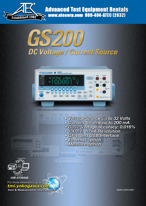
800-404-ATEC (2832) E s t a b l i s h e d1981USBData from the CPUMSBs D-ALSBs D-AOutput ampHighly accurate voltage dividerMultiplicative dual D/A conversionEach DC voltage/current source in the GS200 series uses two DACs to generate highly accurate voltage and current at a high resolution. It is highly stable whether it is used for a short or long period of time and features superb linearity over all the ranges. Moreover, it produces extremely low noise.High accuracy:±0.016% of setting + 240 µV (at 10 V range for one year)±0.03% of setting + 5 µA (at 100 mA range for one year)High stability:±0.001% of setting 20 µV (at 10 V range for one day)±0.004% of setting + 3 µA (at 100 mA range for one day)High resolution:100 nV (VDC, 10 mV range)10 nA (1 mA range)Low noise:100 µVp-p (10 V range, DC to 10 kHz)3 µAp-p (100 mA range, DC to 10 kHz)High Accuracy and High Resolution OutputThe GS200 can perform four-quadrant operation byoperating as a current source or a current sink in the range of ±30 V and ±200 mA.When the GS200 is sinking current, it can operate over the exact same range as when it is operating as a current source. You can use the GS200 not just as a highly accurate voltage source but also as a highly accurate constant-current electronic load.Source and Sink OperationsMeasurement sensors, ICs, consumer electronics, office appliances, communication devices, automotive parts, rechargeable battery control devices, electronic circuits, power supplies, lighting equipment, industrial light sources, small motors, x-ray measuring devices, audio amplifiers, microwave heating equipment, diagnostic imaging equipment, high pressure gas equipment, signal converters, industrial pneumatic equipment, vibration analysis equipment, plant construction, thermal-power and nuclear-power generation facility construction and maintenance, molding and machining, heat treating facilities such as vacuum furnaces and atmosphere furnaces, water quality and atmosphere measuring instruments, tea production lines, etc.Applicable FieldsGeneral SpecificationsVoltage and current source rangeSource operation (highly accurate power supply)Sink operation (highly accurate load)High accuracyHigh stabilityHigh resolutionLow noisematerials• ResistorsPLLs• Smallmotorsmodules• Optical interface modulespower generation - Factories-30V30V Source Sink SinkSourceVoltageCurrent200 mA-200 mAVoltage source up to ±32 V and current source up to ±200 mA51/2-digit, ±120,000-count output resolutionVoltage and current simple monitoring feature (optional)Programmable output up to 10,000 points Built-in USB mass storage deviceChannel expansion through synchronous operationVoltage ranges:10 mV , 100 mV , 1 V , 10 V , and 30 V Maximum output current:±200 mA (at 1 V , 10 V , and 30 V ranges)(A highly accurate voltage divider is used at the 10 mV and 100 mV ranges.)Current ranges: 1 mA, 10 mA, 100 mA, and 200 mA Maximum output voltage: ±30 VGS200GS20004Response time for changing from -32 V to +32 V = Approx. 0.5 msResponse time for changing from -32 V to +32 V = Approx. 200 msApprox. 200 msResponds immediately without discontinuities or glitches when the polarity is inverted.Responds slowly withdiscontinuities when the polarity is inverted.In addition to the GS200’s high accuracy voltage and current source features, it can also be equipped with an optional Simple Voltage and Current Monitoring Feature (Optional)key menus for easy operation.GS200Products with mechanical contact switchesNote) The figures above are for reference only and do not represent the actual product specifications.The monitoring feature can be used to:•Check that current is flowing.GS210Seven segment display on conventional modelsGS200 display and key layout05Rear Panelfront panel). Choose front panel terminals or rear panel terminals depending on your situation.remotely from a PCDC source/monitor SyncDC source/monitorSyncSync24-hour stability values are for 23°C ± 1°C and power fluctuation within ±5%.90-day stability and 90-day and 1-year accuracy values are for 23°C ± 5°C.Add the temperature coefficient for 90-day and 1-year accuracy values for 5°C to 18°C and for 28°C to 40°C.Current Source Section24-hour stability values are for 23°C ±1°C and power fluctuation within ±5%.90-day stability and 90-day and 1-year accuracy values are for 23°C ± 5°C.Add the temperature coefficient for 90-day and 1-year accuracy values for 5°C to 18°C and for 28°C to 40°C.Limiter SectionResponse Time (Typical)10 ms or less for all voltage source and current source ranges.(Response time is the time from the point when the source begins to change until it reaches within 0.1% of the final value at maximum output, maximum load (pure resistive load), and with no limiter operation.)Maximum Capacitive and Inductive LoadsCapacitive load: 10 µFInductive load: 1 mH0607Programming FeatureGeneral SpecificationsExternal dimensionsExternal Input and OutputCommunication InterfaceIntegration time : 1 to 25 PLC T rigger source*: Internal timer (0.1 s to 3600.0 s), READY , communication, and immediate Measurement delay (the delay from the trigger point):0 to 999,999 ms (1 ms resolution)Other features : Auto zero, NULL computation, and data storage* Measurement trigger sourceInternal timer : For monitoring. 0.1 s to 3600.0 s (0.1 s resolution)READY : For curve tracing during program operation. The timing when READY signals are m.: For controlling the GS200 from a PC. Trigger generation through the *TRG command.Immediate : Trigger generation at the end of measurement.Maximum number of steps : 10,000T rigger : External, internal timer, step input, measurement end Slope : 0 s to 3600.0 s (0.1 s resolution)Display : 256 × 64 dot vacuum fluorescent displayInternal memory : 4 MB (non-volatile; stores setup files andoutput pattern files)Warm-up time : At least 60 minutes Operating environment :5 to 40 ºC, 20 to 80% RHRated supply voltage:100 VAC, 120 VAC, 230 VAC(±10% of each rated voltage, 50/60 Hz)Rated supply frequency: 50/60 Hz Maximum power consumption:Approx. 80 VAAllowable input voltage:32 V between the high and low terminals 42 Vpeak between the low and ground terminals0.5 V between the output and sense terminals250 Vpeak between the ground terminal and the caseWeight : Approx. 5 kg External dimensions:Approx. 213 (W) × 88 (H) × 350 (D) mm (excluding protrusions)BNC input/output IN : TRIG IN, OUTPUT IN OUT : TRIG OUT, OUTPUT OUT, READY OUT•GP-IBElectrical and mechanical specifications:Conforms to IEEE Standard 488.2-1987Functional specifications:SH1, AH1, T6, L4, SR1, RL1, PP0, DC1, DT1, C0Protocol : Conforms to IEEE Standard 488.2-1992Addresses : 0 to 30 7651-command-compatible mode available •USB interface Ports : 1Connector : Type BElectrical and mechanical specifications : Conforms to USB 2.0•Ethernet (optional)Ports : 1Connector : RJ-45Electrical and mechanical specifications : Conforms to IEEE 802.3T ransmission system:100BASE-TX/10BASE-TProtocol : FTP server, HTTP server, VXI-11 server,DHCP client, command socketExternal synchronization I/OModel and Suffix Codes Optional Accessories2 pieces (red and black) in 1 set, length: 1.00 mSource Measure Unit GS610Multi Channel Source Measure UnitGS820758933 Measurement lead758917 Measurement lead701901 Safety adapter lead4-mm socket adapter758919 Banana plug set758922 Small alligator clip adapter758929 Large alligator clip adapterSafety terminal-alligator clip cableB9887AR measurement lead (for safety terminals)Banana male-to-binding post adapter751512 conversion adapter366922 conversion adapter701902: Length 1m, 1000V CAT II701902/701903 Safety BNC-BNC cable758923 Safety terminal adapter setSubject to change without notice.[Ed : 01/b] Copyright ©2009Printed in Japan, 911(KP)YOKOGAWA ELECTRIC CORPORATIONMeasurement Business Headquarters /Phone: (81)-422-52-6768, Fax: (81)-422-52-6624E-mail:********YOKOGAWA CORPORATION OF AMERICA Phone: (1)-770-253-7000, Fax: (1)-770-251-6427YOKOGAWA EUROPE B.V.Phone: (31)-88-4641000, Fax: (31)-88-4641111YOKOGAWA ENGINEERING ASIA PTE. LTD.Phone: (65)-62419933, Fax: (65)-62412606MS-19E。
bd62011中文规格书

bd62011中文规格书BD62011中文规格书在BD62011中文规格书中,我们将详细介绍该产品的规格和功能。
BD62011是一款功能强大的设备,适用于各种应用场景。
以下是对该产品规格书的详细解读。
1. 产品介绍BD62011是一款高性能的电子设备,采用先进的技术和设计。
该产品具有多种功能,适用于各种领域,包括工业控制、通信设备和汽车电子等。
2. 主要特性BD62011具有以下主要特性:- 高性能处理器:搭载了先进的处理器,能够快速处理大量数据和复杂计算。
- 多种接口:支持多种接口,包括USB、HDMI、以太网等,方便与其他设备进行连接和通信。
- 大容量存储:内置大容量存储器,能够存储大量数据和文件。
- 高清显示:支持高清显示,显示效果清晰、细腻。
- 多功能操作:支持多种操作模式,包括触摸屏、语音识别和手势控制等。
3. 规格参数- 处理器:采用X1处理器,主频2.4GHz,四核心。
- 存储器:内置8GB闪存和2GB内存。
- 显示屏:5.5英寸高清触摸屏,分辨率为1920x1080。
- 操作系统:基于Android 9.0开发的操作系统。
- 电池容量:3000mAh锂电池,可支持长时间使用。
- 尺寸和重量:151x75x8.1mm,重量约为180g。
4. 功能介绍- 多媒体功能:支持多种媒体格式的播放,包括音乐、视频和图片等。
- 网络通信:支持4G网络通信,能够快速上网和进行在线交流。
- 导航定位:内置GPS芯片,支持导航定位功能,能够准确导航。
- 传感器:内置多种传感器,包括重力感应器、陀螺仪和指纹识别等。
- 扩展接口:支持扩展接口,包括SD卡插槽和耳机接口等。
5. 应用场景BD62011适用于多种应用场景,包括:- 工业控制:可用于工业自动化控制系统,提供可靠的控制和监测功能。
- 通信设备:可用于通信基站、路由器等设备,提供稳定的通信连接和数据传输。
- 汽车电子:可用于汽车导航、娱乐系统等,提供高清显示和多媒体功能。
- 1、下载文档前请自行甄别文档内容的完整性,平台不提供额外的编辑、内容补充、找答案等附加服务。
- 2、"仅部分预览"的文档,不可在线预览部分如存在完整性等问题,可反馈申请退款(可完整预览的文档不适用该条件!)。
- 3、如文档侵犯您的权益,请联系客服反馈,我们会尽快为您处理(人工客服工作时间:9:00-18:30)。
Ultralow V F Hyperfast Rectifierfor Discontinuous Mode PFC, 8 A FRED Pt ®FEATURES•Hyperfast recovery time•Benchmark ultralow forward voltage drop •175 °C operating junction temperature•Low leakage current•Fully isolated package (V INS = 2500 V RMS )•UL E78996 pending•Compliant to RoHS Directive 2002/95/EC•Designed and qualified according to JEDEC-JESD47•Halogen-free according to I EC 61249-2-21 definition (-N3 only)DESCRIPTIONState of the art, ultralow V F , soft-switching hyperfast rectifiers optimized for Discontinuous (Critical) Mode (DCM)Power Factor Correction (PFC).The minimized conduction loss, optimized stored charge and low recovery current minimize the switching losses and reduce over dissipation in the switching element and snubbers.The device is also intended for use as a freewheeling diode in power supplies and other power switching applications.APPLICATIONSAC/DC SMPS 70 W to 400 We.g. laptop and printer AC adaptors, desktop PC, TV and monitor, games units and DVD AC/DC power supplies.PRODUCT SUMMARYPackage TO-220AC, TO-220FPI F(AV)8 A V R 600 V V F at I F 1.05 V t rr typ.60 ns T J max.175 °C Diode variationSingle dieTO-220ACTO-220 FULL-PAKABSOLUTE MAXIMUM RATINGSPARAME ER SYMBOL T ES T CONDI T IONS VALUES UNI T S Repetitive peak reverse voltage V RRM 600VAverage rectified forward current I F(AV)T C = 160 °C 8A FULL-PAKT C = 142 °C Non-repetitive peak surge current I FSM T J = 25 °C175Repetitive peak forward currentI FM 16Operating junction and storage temperaturesT J , T Stg- 65 to 175°C ELECTRICAL SPECIFICATIONS (T J = 25 °C unless otherwise specified)PARAME T ER SYMBOLT ES T CONDI T IONS MIN. T YP. MAX. UNI T S Breakdown voltage,blocking voltage V BR ,V R I R = 100 μA 600--VForward voltage V F I F = 8 A-0.96 1.05I F = 8 A, T J = 150 °C -0.810.86Reverse leakage current I R V R = V R rated-0.055μA T J = 150 °C, V R = V R rated -20100Junction capacitance C T V R = 600 V-17-pF Series inductance L SMeasured lead to lead 5 mm from package body-8.0-nHFig. 1 - Typical Forward Voltage Drop CharacteristicsReverse VoltageDYNAMIC RECOVERY CHARACTERISTICS (T C = 25 °C unless otherwise specified)PARAME T ER SYMBOL T ES T CONDI T IONS MIN. T YP. MAX. UNI T SReverse recovery timet rrI F = 1 A, dI F /dt = 100 A/μs, V R = 30 V-60100nsI F = 8 A, dI F /dt = 100 A/μs, V R = 30 V -150250T J = 25 °C I F = 8 AdI F /dt = 200 A/μs V R = 390 V-170-T J = 125 °C-250-Peak recovery current I RRM T J = 25 °C -15-A T J = 125 °C -20-Reverse recovery chargeQ rrT J = 25 °C - 1.3-μC T J = 125 °C- 2.6-THERMAL - MECHANICAL SPECIFICATIONSPARAME ER SYMBOL T ES T CONDI T IONS MIN. T YP. MAX. UNI T S Maximum junction and storage temperature range T J , T Stg - 65-175°CThermal resistance,junction to caseR thJC - 1.42°C/W (FULL-PAK)- 3.4 4.3Thermal resistance,junction to ambient per leg R thJA Typical socket mount--70Thermal resistance,case to heatsink R thCSMounting surface, flat, smooth and greased-0.5-Weight- 2.0-g -0.07-oz.Mounting torque 6.0(5.0)-12(10)kgf · cm (lbf · in)Marking deviceCase style TO-220AC 8ETL06Case style TO-220 FULL-PAK8ETL06FPFig. 3 - Typical Junction Capacitance vs. Reverse VoltageFig. 4 - Maximum Thermal Impedance Z thJC CharacteristicsFig. 5 - Maximum Thermal Impedance Z thJC Characteristics (FULL-PAK)Fig. 6 - Maximum Allowable Case Temperature vs.Average Forward CurrentFig. 7 - Maximum Allowable Case Temperature vs.Average Forward Current (FULL-PAK)Fig. 8 - Forward Power Loss CharacteristicsFig. 9 - Typical Reverse Recovery Time vs. dI F /dtFig. 10 - Typical Stored Charge vs. dI F /dtNote(1)Formula used: T C = T J - (Pd + Pd REV ) x R thJC ;Pd = Forward power loss = I F(AV) x V FM at (I F(AV)/D) (see fig. 8); Pd REV = Inverse power loss = V R1 x I R (1 - D); I R at V R1 = Rated V RFig. 11 - Reverse Recovery Parameter Test CircuitFig. 12 - Reverse Recovery Waveform and DefinitionsORDERING INFORMATION TABLEORDERING INFORMATION (Example)PREFERRED P/N QUANTITY PER T/R MINIMUM ORDER QUANTITY PACKAGING DESCRIPTION VS-8ETL06PbF501000Antistatic plastic tubeVS-8ETL06-N3501000Antistatic plastic tubeVS-8ETL06FPPbF501000Antistatic plastic tubeVS-8ETL06FP-N3501000Antistatic plastic tubeLINKS TO RELATED DOCUMENTSDimensions TO-220AC /doc?95221 TO-220FP /doc?95005Part marking information TO-220ACPbF /doc?95224 /doc?95068 TO-220FPPbF /doc?95009 /doc?95440Outline Dimensions Vishay SemiconductorsDIMENSIONS in millimetersDocument Number: 95221For technical questions within your region, please contact one of the following:Revision: 07-Mar-11DiodesAmericas@ , DiodesAsia@ , DiodesEurope@1TO-220ACOutline DimensionsVishay SemiconductorsDIMENSIONS in millimeters and inchesNotes(1)Dimensioning and tolerancing as per ASME Y14.5M-1994(2)Lead dimension and finish uncontrolled in L1(3)Dimension D, D1 and E do not include mold flash. Mold flash shall not exceed 0.127 mm (0.005") per side. These dimensions are measured at the outermost extremes of the plastic body(4)Dimension b1, b3 and c1 apply to base metal only (5)Controlling dimension: inches(6)Thermal pad contour optional within dimensions E, H1, D2 and E1(7)Dimension E2 x H1 define a zone where stamping and singulation irregularities are allowed(8)Outline conforms to JEDEC TO-220, D2 (minimum) where dimensions are derived from the actual package outlineSYMBOLMILLIMETERS INCHES NOTES SYMBOLMILLIMETERS INCHES NOTES MIN.MAX.MIN.MAX.MIN.MAX.MIN.MAX.A 4.25 4.650.1670.183E1 6.868.890.2700.3506A1 1.14 1.400.0450.055E2-0.76-0.0307A2 2.56 2.920.1010.115e 2.41 2.670.0950.105b 0.69 1.010.0270.040e14.885.280.1920.208b10.380.970.0150.0384H16.09 6.480.2400.2556, 7b2 1.20 1.730.0470.068L 13.5214.020.5320.552b3 1.14 1.730.0450.0684L1 3.32 3.820.1310.1502c 0.360.610.0140.024L3 1.78 2.130.0700.084c10.360.560.0140.0224L40.76 1.270.0300.0502D 14.8515.250.5850.6003Ø P 3.54 3.730.1390.147D18.389.020.3300.355Q 2.603.000.1020.118D211.6812.880.4600.507690° to 93°90° to 93°E10.1110.510.3980.4143, 6Legal Disclaimer Notice VishayDisclaimerALL PRODU CT, PRODU CT SPECIFICATIONS AND DATA ARE SU BJECT TO CHANGE WITHOU T NOTICE TO IMPROVE RELIABILITY, FUNCTION OR DESIGN OR OTHERWISE.Vishay Intertechnology, Inc., its affiliates, agents, and employees, and all persons acting on its or their behalf (collectively,“Vishay”), disclaim any and all liability for any errors, inaccuracies or incompleteness contained in any datasheet or in any other disclosure relating to any product.Vishay makes no warranty, representation or guarantee regarding the suitability of the products for any particular purpose or the continuing production of any product. To the maximum extent permitted by applicable law, Vishay disclaims (i) any and all liability arising out of the application or use of any product, (ii) any and all liability, including without limitation special, consequential or incidental damages, and (iii) any and all implied warranties, including warranties of fitness for particular purpose, non-infringement and merchantability.Statements regarding the suitability of products for certain types of applications are based on Vishay’s knowledge of typical requirements that are often placed on Vishay products in generic applications. Such statements are not binding statements about the suitability of products for a particular application. It is the customer’s responsibility to validate that a particular product with the properties described in the product specification is suitable for use in a particular application. Parameters provided in datasheets and/or specifications may vary in different applications and performance may vary over time. All operating parameters, including typical parameters, must be validated for each customer application by the customer’s technical experts. Product specifications do not expand or otherwise modify Vishay’s terms and conditions of purchase, including but not limited to the warranty expressed therein.Except as expressly indicated in writing, Vishay products are not designed for use in medical, life-saving, or life-sustaining applications or for any other application in which the failure of the Vishay product could result in personal injury or death. Customers using or selling Vishay products not expressly indicated for use in such applications do so at their own risk and agree to fully indemnify and hold Vishay and its distributors harmless from and against any and all claims, liabilities, expenses and damages arising or resulting in connection with such use or sale, including attorneys fees, even if such claim alleges that Vishay or its distributor was negligent regarding the design or manufacture of the part. Please contact authorized Vishay personnel to obtain written terms and conditions regarding products designed for such applications.No license, express or implied, by estoppel or otherwise, to any intellectual property rights is granted by this document or by any conduct of Vishay. Product names and markings noted herein may be trademarks of their respective owners.Material Category PolicyVishay Intertechnology, Inc. hereb y certifies that all its products that are identified as RoHS-Compliant fulfill the definitions and restrictions defined under Directive 2011/65/EU of The European Parliament and of the Council of June 8, 2011 on the restriction of the use of certain hazardous substances in electrical and electronic equipment (EEE) - recast, unless otherwise specified as non-compliant.Please note that some Vishay documentation may still make reference to RoHS Directive 2002/95/EC. We confirm that all the products identified as being compliant to Directive 2002/95/EC conform to Directive 2011/65/EU.Revision: 12-Mar-121Document Number: 91000分销商库存信息:VISHAY8ETL06FPPBF8ETL068ETL06FP。