IPB15N03L中文资料
防护等级

IP防护等级介绍IP防护等级说明(按照EN60529/IEC529)防护等级IP54,IP为标记字母,数字5为第一标记数字,4为第二标记数字第一标记数字表示接触保护和外来物保护等级,第二标记数字表示防水保护等级;接触保护和外来物保护等级(第一个数字) 防水保护等级( 第二个数字)第一个数字防护范围第二个数字防护范围名称说明名称说明0 无防护- 0 无防护–1 防护50mm直径和更大的固体外来体探测器,球体直径为50mm,不应完全进入1 水滴防护垂直落下的水滴不应引起损害2 防护12.5mm直径和更大的固体外来体探测器,球体直径为12.5mm,不应完全进入2 柜体倾斜15度时,防护水滴柜体向任何一侧倾斜15度角时,垂直落下的水滴不应引起损害3 防护2.5mm直径和更大的固体外来体探测器,球体直径为2.5mm,不应完全进入3 防护溅出的水以60度角从垂直线两侧溅出的水不应引起损害4 防护1.0mm直径和更大的固体外来体探测器,球体直径为1.0mm,不应完全进入4 防护喷水从每个方向对准柜体的喷水都不应引起损害5 防护灰尘不可能完全阻止灰尘进入,但灰尘进入的数量不会对设备造成伤害5 防护射水从每个方向对准柜体的射水都不应引起损害6 灰尘封闭柜体内在20毫巴的低压时不应进入灰尘6 防护强射水从每个方向对准柜体的强射水都不应引起损害注:探测器的直径不应穿过柜体的孔7 防护短时浸水柜体在标准压力下短时浸入水中时,不应有能引起损害的水量浸入8 防护长期浸水可以在特定的条件下浸入水中,不应有能引起损害的水量浸技术文摘- 防水试验1、范围防水试验包括第二位特征数字为1至8,即防护等级代码为IPX1至IPX8。
2、各种等级的防水试验内容(1)IPX1 方法名称:垂直滴水试验试验设备:滴水试验装置及其试验方法见2.11 试样放置:按试样正常工作位置摆放在以1r/min的旋转样品台上,样品顶部至滴水口的距离不大于200mm 试验条件:滴水量为1 0.5 mm/min;试验持续时间:10 min;(2)IPX2 方法名称:倾斜15°滴水试验试验设备:滴水试验装置及其试验方法见 2.11 试样放置:使试样的一个面与垂线成15°角,样品顶部至滴水口的距离不大于200mm。
工业器材防尘防水的等级

IP65
IP等级(防尘防水)定义中一项:IP65 IP是Ingress Protection的缩写,IP等级是针对电气设备外壳对异物侵入的防护等级,如:防爆电器,防水防尘电器,来源是国际电工委员会的标准IEC 60529,这个标准在2004年也被采用为美国国家标准。
在这个标准中,针对电气设备外壳对异物的防护,IP等级的格式为IPXX,其中XX为两个阿拉伯数字,第一标记数字表示接触保护和外来物保护等级,第二标记数字表示防水保护等级,具体的防护等级可以参考下面的表格。
IP是国际用来认定防护等级的代号Ip等级由两个数字所组成,第一个数字表示防尘;第二个数字由表示防水,数字越大表示其防护等级越佳。
防尘等级
号码防护程度定义
参照标准:GB 4208 2008 《外壳防护等级(IP代码)》
IPxx
防尘等级(第一个X表示)
0:没有保护
1:防止大的固体侵入
2:防止中等大小的固体侵入
3:防止小固体进入侵入
4:防止物体大于1mm的固体进入
5:防止有害的粉尘堆积
6:完全防止粉尘进入
防水等级(第二个X表示)
0:没有保护
1:水滴滴入到外壳无影响
2:当外壳倾斜到15度时,水滴滴入到外壳无影响
3:水或雨水从60度角落到外壳上无影响
4:液体由任何方向泼到外壳没有伤害影响
5:用水冲洗无任何伤害
6:可用于船舱内的环境
7:可于短时间内耐浸水(1m)
8:于一定压力下长时间浸水
检测时请注意:
IP65 包括2个试验:IP6X 和IPX5
IP6X 检测时会对产品内部抽气,产生负压!
IPX5 3米外小水枪冲水!。
IP5353规格书
IP5353规格书
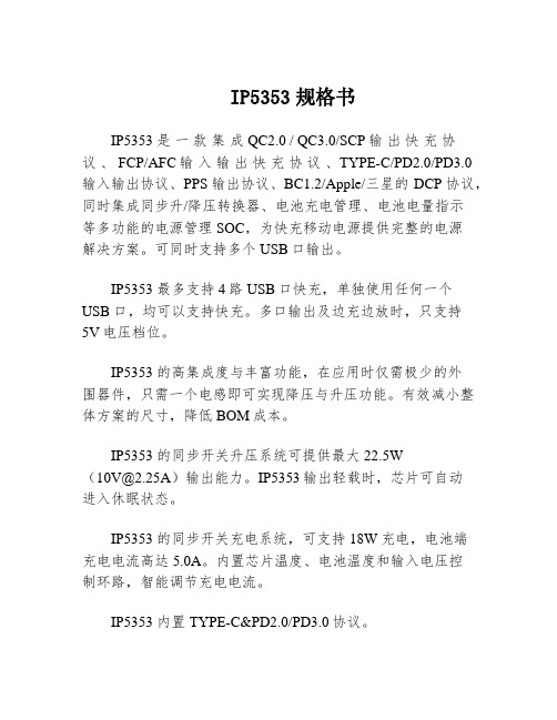
IP5353 是一款集成QC2.0 / QC3.0/SCP输出快充协
议、 FCP/AFC输入输出快充协议、TYPE-C/PD2.0/PD3.0
输入输出协议、PPS输出协议、BC1.2/Apple/三星的DCP协议,同时集成同步升/降压转换器、电池充电管理、电池电量指示
等多功能的电源管理SOC,为快充移动电源提供完整的电源
解决方案。
可同时支持多个USB口输出。
IP5353 最多支持4路USB口快充,单独使用任何一个USB口,均可以支持快充。
多口输出及边充边放时,只支持
5V电压档位。
IP5353 的高集成度与丰富功能,在应用时仅需极少的外
围器件,只需一个电感即可实现降压与升压功能。
有效减小整体方案的尺寸,降低BOM成本。
IP5353 的同步开关升压系统可提供最大22.5W
(*********)输出能力。
IP5353输出轻载时,芯片可自动
进入休眠状态。
IP5353 的同步开关充电系统,可支持18W充电,电池端
充电电流高达5.0A。
内置芯片温度、电池温度和输入电压控
制环路,智能调节充电电流。
IP5353 内置TYPE-C&PD2.0/PD3.0协议。
IP5353 支持4颗LED电量显示、照明功能、按键功能。
IP5353 支持I2C控制接口。
Philips M310 M315 产品说明书
Call log
Call from the call log
1 Press . 2 Select a record and press .
View record
Press > > [View].
Save record
1 Press > > [Save number]. 2 Follow on-screen instructions.
1 Overview
In call Enter the option menu. Access the redial list. Adjust the volume. Recall (network dependent). End calls. Enter a pause (press and hold). Turn the speaker on/off. Mute/unmute the microphone.
Delete record
1 Press > > [Delete]. 2 Follow on-screen instructions.
Redial list
Call from the redial list 1 Press . 2 Select a record and press .
Save record 1 Press > > [Save number]. 2 Follow on-screen instructions.
incorrect type. • Dispose of used batteries according to the
instructions. • When the handset rings or when the handsfree is
dini03技术参数
dini03技术参数DINI03技术参数DINI03是一款先进的技术产品,拥有许多令人瞩目的技术参数。
本文将详细介绍DINI03的各项技术参数,以便更好地了解该产品。
1. 处理器性能DINI03采用了先进的处理器技术,搭载高性能的处理器单元。
这款处理器采用了多核架构,能够同时处理多个任务。
与传统处理器相比,DINI03的处理器性能更强,能够提供更快的计算速度和更高的效率。
2. 存储容量DINI03内置大容量存储器,可以存储大量的数据。
其存储容量可根据用户需求进行定制,从几十GB到几TB不等。
这使得DINI03成为处理大数据的理想选择,能够满足各种数据存储需求。
3. 网络连接DINI03具备强大的网络连接功能,支持多种通信协议和接口。
它可以通过以太网、无线网络等方式与其他设备进行连接,实现数据的传输和共享。
这使得DINI03可以与其他设备进行高效的数据交换,满足复杂的通信需求。
4. 数据安全DINI03在数据安全方面具有出色的性能。
它支持多种加密算法和安全协议,能够对数据进行可靠的加密和解密。
此外,DINI03还提供了强大的访问控制功能,可以限制对数据的访问权限,防止未经授权的人员获取敏感信息。
5. 电源管理DINI03具备先进的电源管理功能,能够高效利用电能资源。
它采用了低功耗设计,可以在保证性能的同时降低能耗。
此外,DINI03还支持多种电源模式,可以根据实际需求进行灵活调整,进一步提高能源利用效率。
6. 系统稳定性DINI03采用了高可靠性的硬件和软件设计,保证了系统的稳定性和可靠性。
它具备自动故障检测和恢复功能,能够快速识别和处理故障,保证系统的连续运行。
此外,DINI03还支持远程监控和管理,可以实时监测系统状态,及时采取措施,提高系统的可靠性和可用性。
7. 扩展性DINI03具有良好的扩展性,可以根据用户需求进行功能扩展和定制。
它支持多种接口和扩展槽位,可以连接各种外部设备和模块。
这使得DINI03具备了更广泛的应用场景和更强大的功能扩展能力。
IPB09N03_DataSheet
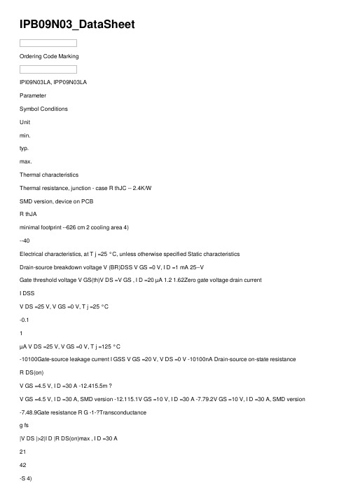
IPB09N03_DataSheetOrdering Code MarkingIPI09N03LA, IPP09N03LAParameterSymbol ConditionsUnitmin.typ.max.Thermal characteristicsThermal resistance, junction - case R thJC -- 2.4K/WSMD version, device on PCBR thJAminimal footprint --626 cm 2 cooling area 4)--40Electrical characteristics, at T j =25 °C, unless otherwise specified Static characteristicsDrain-source breakdown voltage V (BR)DSS V GS =0 V, I D =1 mA 25--VGate threshold voltage V GS(th)V DS =V GS , I D =20 µA 1.2 1.62Zero gate voltage drain currentI DSSV DS =25 V, V GS =0 V, T j =25 °C-0.11µA V DS =25 V, V GS =0 V, T j =125 °C-10100Gate-source leakage current I GSS V GS =20 V, V DS =0 V -10100nA Drain-source on-state resistanceR DS(on)V GS =4.5 V, I D =30 A -12.415.5m ?V GS =4.5 V, I D =30 A, SMD version -12.115.1V GS =10 V, I D =30 A -7.79.2V GS =10 V, I D =30 A, SMD version -7.48.9Gate resistance R G -1-?Transconductanceg fs|V DS |>2|I D |R DS(on)max , I D =30 A2142-S 4)Device on 40 mm x 40 mm x 1.5 mm epoxy PCB FR4 with 6 cm 2 (one layer, 70 µm thick) copper area for drain connection. PCB is vertical in still air.Values 1)Current is limited by bondwire; with an R thJC =2.4 K/W the chip is able to carry 64 A.2) See figure 33) T j,max =150 °C and duty cycle D <0.25 for V GS <-5 VIPI09N03LA, IPP09N03LA Parameter Symbol Conditions Unitmin.typ.max. Dynamic characteristicsInput capacitance C iss-12401649pF Output capacitance C oss-530704 Reverse transfer capacitance C rss-81122Turn-on delay time t d(on)-913ns Rise time t r-88132Turn-off delay time t d(off)-2233Fall time t f- 4.26Gate Charge Characteristics5)Gate to source charge Q gs- 4.4 5.8nC Gate charge at threshold Q g(th)- 2.0 2.6Gate to drain charge Q gd- 3.1 4.7 Switching charge Q sw- 5.57.9Gate charge total Q g-1014Gate plateau voltage V plateau- 3.5-VGate charge total, sync. FET Q g(sync)V DS=0.1 V,V GS=0 to 5 V-912nCOutput charge Q oss V DD=15 V, V GS=0 V-1115 Reverse DiodeDiode continous forward current I S--50A Diode pulse current I S,pulse--350Diode forward voltage V SD V GS=0 V, I F=50 A,T j=25 °C-0.98 1.2VReverse recovery charge Q rr V R=15 V, I F=I S,d i F/d t=400 A/µs--10nC5) See figure 16 for gate charge parameter definition T C=25 °CValuesV GS=0 V, V DS=15 V,f=1 MHzV DD=15 V, V GS=10 V,I D=25 A, R G=2.7 ?V DD=15 V, I D=25 A,V GS=0 to 5 VIPI09N03LA, IPP09N03LA Package OutlineP-TO263-3-2: OutlineFootprint PackagingIPI09N03LA, IPP09N03LA P-TO262-3-1: OutlineP-TO220-3-1: OutlinePackagingIPI09N03LA, IPP09N03LA Published byInfineon Technologies AGBereich KommunikationSt.-Martin-Stra?e 53D-81541 MünchenInfineon Technologies AG 1999All Rights Reserved.Attention please!The information herein is given to describe certain components and shall not be considered aswarranted characteristics.Terms of delivery and rights to technical change reserved.We hereby disclaim any and all warranties, including but not limited to warranties of non-infringement, regarding circuits, descriptions and charts started herein.Infineon Technologies is an approved CECC manufacturer.InformationFor further information on technology, delivery terms and conditions and prices, please contact your nearest Infineon Technologies office in Germany or our Infineon Technologies representatives worldwide (see address list).WarningsDue to technical requirements, components may contain dangerous substances.For information on the types in question, please contact your nearest Infineon Technologies office. Infineon Technologies' components may only be used in life-support devices or systems with the expressed written approval of Infineon Technologies if a failure of such components can reasonablybe expected to cause the failure of that life-support device or system, or to affect the safety or effectiveness of that device or system. Life support devices or systems are intended to be implantedin the human body, or to support and/or maintain and sustain and/or protect human life. If they fail,it is reasonable to assume that the health of the user or other persons may be endangered.。
IPP10N03L中文资料

IPB10N03LOpti MOS ® Buck converter seriesProduct Summary V DS30V R DS(on) max. SMD version 8.9m ΩID73AFeature• N-Channel• Logic Level• Low On-Resistance R DS(on)• Excellent Gate Charge x R DS(on) product (FOM)• Superior thermal resistance• 175°C operating temperature • Avalanche rated • d v /d t rated• Ideal for fast switching buck convertersP- TO263 -3-2P- TO220 -3-1Marking 10N03L 10N03LType Package Ordering Code IPP10N03L P- TO220 -3-1Q67042-S4040IPB10N03L P- TO263 -3-2Q67040-S4346Maximum Ratings , at T j = 25 °C, unless otherwise specifiedParameterSymbol Value Unit Continuous drain current 1)T C =25°CI D7363APulsed drain currentT C =25°CI D puls 292Avalanche energy, single pulseI D =30A, V DD =25V, R GS =25ΩE AS 25mJRepetitive avalanche energy, limited by T jmax 2)E AR 10Reverse diode d v /d tI S =73A, V DS =24, d i /d t =200A/µs, T jmax =175°Cd v /d t 6kV/µs Gate source voltage V GS ±20V Power dissipationT C =25°CP tot 107W Operating and storage temperature T j , T stg-55... +175°C IEC climatic category; DIN IEC 68-155/175/56IPB10N03LThermal Characteristics Parameter SymbolValues Unitmin.typ.max.CharacteristicsThermal resistance, junction - case R thJC -0.9 1.4K/WSMD version, device on PCB:@ min. footprint @ 6 cm 2 cooling area 3)R thJA---- 6240Electrical Characteristics , at T j = 25 °C, unless otherwise specified ParameterSymbolValues Unitmin.typ.max.Static CharacteristicsDrain-source breakdown voltageV GS =0V, I D =1mAV (BR)DSS 30--VGate threshold voltage, V GS = V DSI D =60µAV GS(th) 1.2 1.62Zero gate voltage drain currentV DS =30V, V GS =0V, T j =25°C V DS =30V, V GS =0V, T j =175°CI DSS-- 0.0110 1100µAGate-source leakage currentV GS =20V, V DS =0VI GSS -1100nA Drain-source on-state resistanceV GS =4.5V, I D =36AV GS =4.5V, I D =36A, SMD versionR DS(on)-- 9.99.5 13.413.1m ΩDrain-source on-state resistance 4)V GS =10V, I D =36AV GS =10V, I D =36A, SMD versionR DS(on)--6.86.59.28.91Current limited by bondwire ; with an RthJC = 1.4K/W the chip is able to carry I D = 88A at 25°C, for detailed information see app.-note ANPS071E available at /optimos 2Defined by design. Not subject to production test.3Device on 40mm*40mm*1.5mm epoxy PCB FR4 with 6cm² (one layer, 70 µm thick) copper area for drain connection. PCB is vertical without blown air.4Diagrams are related to straight lead versionsIPB10N03LElectrical Characteristics ParameterSymbol ConditionsValues Unitmin.typ.max.Dynamic Characteristics Transconductance g fs V DS ≥2*I D *R DS(on)max , I D =63A3263-SInput capacitance C iss V GS =0V, V DS =25V, f =1MHz-12901710pF Output capacitanceC oss -500670Reverse transfer capacitance C rss -130190Gate resistance R G -1.4-ΩTurn-on delay time t d(on)V DD =15V, V GS =10V, I D =18A, R G =4.7Ω-7.711.6nsRise timet r -2030Turn-off delay time t d(off)-31.547.3Fall timet f -1928.5Gate Charge Characteristics Gate to source charge Q gs V DD =15V, I D =36A-45nCGate to drain charge Q gd -10.613.3Gate charge total Q g V DD =15V, I D =36A, V GS =0 to 5V -1923.8Output charge Q ossV DS =15V, I D =36A, V GS =0V-18.222.8nC Gate plateau voltage V (plateau)V DD =15V, I D =36A -3.6-VReverse DiodeInverse diode continuous forward currentI ST C =25°C--73AInv. diode direct current, pulsed I SM --292Inverse diode forward voltage V SD V GS =0V, I F =73A -0.96 1.28V Reverse recovery time t rr V R =15V, I F =l S , d i F /d t =100A/µs-32.941.2ns Reverse recovery chargeQ rr-3341nCIPB10N03L1 Power dissipation P tot = f (T C )P t o t2 Drain current I D = f (T C )parameter: V≥ 10 VI D4 Max. transient thermal impedance Z thJC = f (t p )parameter : D = t/T10 10 10 10 10 10 K/WZ t h JC3 Safe operating area I D = f ( V DS )parameter : D = 0 , T = 25 °C2I DIPB10N03L5 Typ. output characteristic I D = f (V DS ); T j =25°C parameter: t= 80 µsI D6 Typ. drain-source on resistance R DS(on) = f (I D )parameter: V R D S (o n )7 Typ. transfer characteristics I D = f ( V GS ); V DS ≥ 2 x I D x R DS(on)max parameter: t p = 80 µsI D8 Typ. forward transconductance g fs = f(I D ); T j =25°C parameter: g fsg f sIPB10N03L9 Drain-source on-state resistance R DS(on) = f (T j )parameter : I= 36 A, V = 10 VR D S (o n)10 Typ. gate threshold voltage V GS(th) = f (T j )parameter: V GS = V DSV G S (t h )11 Typ. capacitances C = f (V DS )parameter: V GS =0V, f =1 MHzC12 Forward character. of reverse diode I F = f (V SD )parameter: T, t p = 80 µsI FIPB10N03L13 Typ. avalanche energy E AS = f (T j )par.: I D = 30 A, V DD = 25 V, R GS = 25 Ω14 Typ. gate charge V GS = f (Q Gate )parameter: I = 36 A pulsedVG S15 Drain-source breakdown voltage V (BR)DSS = f (T j )parameter: I =10 mAV (B R )D S SIPB10N03L Published byInfineon Technologies AG,Bereichs KommunikationSt.-Martin-Strasse 53,D-81541 München© Infineon Technologies AG 1999All Rights Reserved.Attention please!The information herein is given to describe certain components and shall not be considered as warranted characteristics.Terms of delivery and rights to technical change reserved.We hereby disclaim any and all warranties, including but not limited to warranties of non-infringement,regarding circuits, descriptions and charts stated herein.Infineon Technologies is an approved CECC manufacturer.InformationFor further information on technology, delivery terms and conditions and prices please contact your nearestInfineon Technologies Office in Germany or our Infineon Technologies Reprensatives worldwide (see address list). WarningsDue to technical requirements components may contain dangerous substances.For information on the types in question please contact your nearest Infineon Technologies Office.Infineon Technologies Components may only be used in life-support devices or systems with the expresswritten approval of Infineon Technologies, if a failure of such components can reasonably be expected tocause the failure of that life-support device or system, or to affect the safety or effectiveness of that deviceor system Life support devices or systems are intended to be implanted in the human body, or to supportand/or maintain and sustain and/or protect human life. If they fail, it is reasonable to assume that the healthof the user or other persons may be endangered.。
IP防护等级介绍

IP防护等级介绍IP防护等级说明(按照EN60529/IEC529)防护等级IP54, IP为标记字母,数字5为第一标记数字,4为第二标记数字第一标记数字表示接触保护和外来物保护等级,第二标记数字表示防水保护等级;技术文摘 - 防水试验1、范围防水试验包括第二位特征数字为1至8,即防护等级代码为IPX1至IPX8。
2、各种等级的防水试验内容(1)IPX1方法名称:垂直滴水试验试验设备:滴水试验装置及其试验方法见2.11试样放置:按试样正常工作位置摆放在以1r/min的旋转样品台上,样品顶部至滴水口的距离不大于200mm试验条件:滴水量为1 0.5 mm/min;试验持续时间:10 min;(2)IPX2方法名称:倾斜 15°滴水试验试验设备:滴水试验装置及其试验方法见2.11试样放置:使试样的一个面与垂线成15°角,样品顶部至滴水口的距离不大于200mm。
每试完一个面后,换另一个.....面,共四次。
试验条件:滴水量为3 0.5 mm/min;试验持续时间:4×2.5 min(共10 min);(3)IPX3方法名称:淋水试验试验方法:a.摆管式淋水试验试验设备:摆管式淋水溅水试验装置(装置图形及其试验方法见本书2.14)试样放置:选择适当半径的摆管,使样品台面高度处于摆管直径位置上,将试样放在样台上,使其顶部到样品喷水口的距离不大于200mm,样品台不旋转。
试验条件:水流量按摆管的喷水孔数计算,每孔为 0.07 L/min。
淋水时,摆管中点两边各60°弧段内的喷水孔的喷水喷向样品。
被试样品放在摆管半圆中心。
摆管沿垂线两边各摆动60°,共120°。
每次摆动(2×120°)约4s 。
试验时间:连续淋水10 min 。
b.喷头式淋水试验试验设备:手持式淋水溅水试验装置,装置图形及其试验方法见本书2.14试样放置:使试验顶部到手持喷头喷水口的平行距离在300mm至500mm之间试验条件:试验时应安装带平衡重物的挡板,水流量为10 L/min试验时间:按被检样品外壳表面积计算,每平方米为1 min (不包括安装面积),最少5 min 。
- 1、下载文档前请自行甄别文档内容的完整性,平台不提供额外的编辑、内容补充、找答案等附加服务。
- 2、"仅部分预览"的文档,不可在线预览部分如存在完整性等问题,可反馈申请退款(可完整预览的文档不适用该条件!)。
- 3、如文档侵犯您的权益,请联系客服反馈,我们会尽快为您处理(人工客服工作时间:9:00-18:30)。
IPB15N03LOpti MOS ® Buck converter seriesProduct Summary V DS30V R DS(on) max. SMD version 12.6m ΩID42AFeature• N-Channel• Logic Level• Low On-Resistance R DS(on)• Excellent Gate Charge x R DS(on) product (FOM)• Superior thermal resistance• 175°C operating temperature • Avalanche rated • d v /d t rated• Ideal for fast switching buck convertersP- TO263 -3-2P- TO220 -3-1Marking 15N03L 15N03LType Package Ordering Code IPP15N03L P- TO220 -3-1Q67042-S4039IPB15N03L P- TO263 -3-2Q67040-S4344Maximum Ratings , at T j = 25 °C, unless otherwise specifiedParameterSymbol Value Unit Continuous drain current 1)T C =25°CI D4242APulsed drain currentT C =25°CI D puls 168Avalanche energy, single pulseI D =20A, V DD =25V, R GS =25ΩE AS 20mJRepetitive avalanche energy, limited by T jmax 2)E AR 8Reverse diode d v /d tI S =42A, V DS =-V, d i /d t =200A/µs, T jmax =175°Cd v /d t 6kV/µs Gate source voltage V GS ±20V Power dissipationT C =25°CP tot 83W Operating and storage temperature T j , T stg-55... +175°C IEC climatic category; DIN IEC 68-155/175/56IPB15N03LThermal Characteristics Parameter SymbolValues Unitmin.typ.max.CharacteristicsThermal resistance, junction - case R thJC - 1.2 1.8K/WSMD version, device on PCB:@ min. footprint @ 6 cm 2 cooling area 3)R thJA---- 6240Electrical Characteristics , at T j = 25 °C, unless otherwise specified ParameterSymbolValues Unitmin.typ.max.Static CharacteristicsDrain-source breakdown voltageV GS =0V, I D =1mAV (BR)DSS 30--VGate threshold voltage, V GS = V DSI D =40µAV GS(th) 1.2 1.62Zero gate voltage drain currentV DS =30V, V GS =0V, T j =25°C V DS =30V, V GS =0V, T j =125°CI DSS-- 0.0110 1100µAGate-source leakage currentV GS =20V, V DS =0VI GSS -1100nA Drain-source on-state resistanceV GS =4.5V, I D =21AV GS =4.5V, I D =21A, SMD versionR DS(on)-- 14.914.5 19.919.6m ΩDrain-source on-state resistanceV GS =10V, I D =21AV GS =10V, I D =21A, SMD versionR DS(on)--10.39.912.912.61Current limited by bondwire ; with an RthJC = 1.8K/W the chip is able to carry I D = 64A at 25°C, for detailed information see app.-note ANPS071E available at /optimos 2Defined by design. Not subject to production test.3Device on 40mm*40mm*1.5mm epoxy PCB FR4 with 6cm² (one layer, 70 µm thick) copper area for drain connection. PCB is vertical without blown air.IPB15N03LElectrical Characteristics ParameterSymbol ConditionsValues Unitmin.typ.max.Dynamic Characteristics Transconductance g fs V DS ≥2*I D *R DS(on)max , I D =42A2142-SInput capacitance C iss V GS =0V, V DS =25V, f =1MHz-8501130pF Output capacitanceC oss -330330Reverse transfer capacitance C rss -90130Gate resistance R G -1-ΩTurn-on delay time t d(on)V DD =15V, V GS =10V, I D =21A, R G =7.8Ω- 6.59.8nsRise timet r -2030Turn-off delay time t d(off)-2436Fall timet f -14.521.8Gate Charge Characteristics Gate to source charge Q gs V DD =15V, I D =21A- 2.7 3.6nCGate to drain charge Q gd -7.49.3Gate charge total Q g V DD =15V, I D =21A, V GS =0 to 5V -12.715.9Output charge Q ossV DS =15V, I D =21A, V GS =0V-12.215.3nC Gate plateau voltage V (plateau)V DD =15V, I D =21A -3.5-VReverse DiodeInverse diode continuous forward currentI ST C =25°C--42AInv. diode direct current, pulsed I SM --168Inverse diode forward voltage V SD V GS =0V, I F =42A -0.95 1.25V Reverse recovery time t rr V R =-V, I F =l S , d i F /d t =100A/µs-2431ns Reverse recovery chargeQ rr-1823nCIPB15N03L1 Power dissipation P tot = f (T C )P t o t2 Drain current I D = f (T C )parameter:V≥ 10 VI D4 Max. transient thermal impedance ZthJC = f (t p )parameter : D = t/T10 10 10 10 10 10 K/WZ t h JC3 Safe operating area I D = f ( V DS )parameter : D = 0 , T = 25 °C2I DIPB15N03L5 Typ. output characteristic I D = f (V DS ); T j =25°C parameter: t= 80 µsI D6 Typ. drain-source on resistance R DS(on) = f (I D )parameter: Vm Ω65R D S (o n )7 Typ. transfer characteristics I D = f ( V GS ); V DS ≥ 2 x I D x R DS(on)max parameter: t p = 80 µsI D8 Typ. forward transconductance g fs = f(I D ); T j =25°C parameter: g fsg f sIPB15N03L9 Drain-source on-state resistance R DS(on) = f (T j )parameter : I D = 21 A, VGS = 10 Vm Ω30IPP15N03LR D S (o n)10 Typ. gate threshold voltage V GS(th) = f (T j )parameter: V GS = V DSV G S (t h)11 Typ. capacitances C = f (V DS )parameter: V GS =0V, f =1 MHzp F12 Forward character. of reverse diode I F = f (V SD )parameter: T, t p = 80 µsI FIPB15N03L13 Typ. avalanche energy E AS = f (T j )par.: I D = 20 A, V DD = 25 V, R GS = 25 Ω14 Typ. gate charge V GS = f (Q Gate )parameter: I= 21 A pulsedV GS15 Drain-source breakdown voltage V (BR)DSS = f (T j )parameter: I =10 mAV (B R )D S SIPB15N03L Published byInfineon Technologies AG,Bereichs KommunikationSt.-Martin-Strasse 53,D-81541 München© Infineon Technologies AG 1999All Rights Reserved.Attention please!The information herein is given to describe certain components and shall not be considered as warranted characteristics.Terms of delivery and rights to technical change reserved.We hereby disclaim any and all warranties, including but not limited to warranties of non-infringement,regarding circuits, descriptions and charts stated herein.Infineon Technologies is an approved CECC manufacturer.InformationFor further information on technology, delivery terms and conditions and prices please contact your nearestInfineon Technologies Office in Germany or our Infineon Technologies Reprensatives worldwide (see address list). WarningsDue to technical requirements components may contain dangerous substances.For information on the types in question please contact your nearest Infineon Technologies Office.Infineon Technologies Components may only be used in life-support devices or systems with the expresswritten approval of Infineon Technologies, if a failure of such components can reasonably be expected tocause the failure of that life-support device or system, or to affect the safety or effectiveness of that deviceor system Life support devices or systems are intended to be implanted in the human body, or to supportand/or maintain and sustain and/or protect human life. If they fail, it is reasonable to assume that the healthof the user or other persons may be endangered.。