W366 training(平渠版)
中专考大专的刷题软件免费的有哪些
中专考大专的刷题软件免费的有哪些
中专考大专免费的刷题软件:洋葱学园:这个软件主要是针对数学这一科目的学习,如果你到中专或者大专的专业是与数学有关的那你用这个软件就非常合适,里面会有一些名师在线为大家讲授题目,所有的练习题也配有了相应的解析。
1
《天天练》
快用天天练这个APP可以用科学的方法让中专秒懂知识点,刷题刷出真正的学霸,精要知识点短视频,涵盖了中专考大专各个年级的内容和习题,要把理论知识与实际操作练习起来,这样才能更好的体会每个知识点。
《高途》
成人职业在线教育平台,每一个小伙伴提供终身学习的理念和途径,而且软件中的教师平均教龄已经在十年以上了,金牌辅导全程督学,帮助中专生攻克考试当中的重难点,考老师和公务员等等的全都可以。
2
1、普通高考:普通高考无疑是获取一个社会承认度最高学历的一个途径,但是中专生再去参加高考,考试会比较困难,比一般高中生可能还要困难,因为毕竟没有系统地学习过高中的课程。
2、对口和单招:中专生通过对口和单招获取的学历和高招是一样的。
考试会相对来说容易一点。
只能报考一个单招学校的一个专业,选择性小,一旦选定学校和专业就不能再变更。
3、成人自考:自考没有入学考试,只需要参加相应的课程考试,所有课程考试合格后,符合毕业条件即可申请大专毕业证书。
4、成人高考:成人高考是有一个全国统一的入学考试的,考试后所报考的院校会根据所制定的分数线择优录取考生,录满为止。
考试相对简单,升大专考语数外三科,通过率高。
GoldWave5_17汉化版软件在英语听力课中的简单应用

GoldWave5_17汉化版软件在英语听力课中的简单应用录音材料, 但是我们有时只是需要其中的某一段。
或者, 当我们 , 其它的阴影部分不会受到影响。
会对这个高亮度区域进行要进行听力训练时, 材料往往速度过快, 在多媒体播放器上很难把握中间停顿, 导致学生听力疲倦。
又或者, 当我们想进行听写训练时, 往往去找过去的样题, 但有的录音样本中间的停顿时间太短或根本没有停顿, 这时该怎么办? 其实以上问题我们都可以用汉化版来解决。
5. 17 Go ldW ave软件大小: 1967KB软件类别: 汉化补丁音频工具ƒ软件语言: 简体中文运行环境: 9ƒƒƒ2000ƒƒ2003W inx M eN T X P5. 17 汉化版是一个集声音编辑, 播放, 录制, 和 Go ldW ave转换的音频工具, 体积小巧。
可打开的音频文件相当多, 包括, , , , , , , , 3, W A V O GGV O C IF F A IF A FC A U SN D MP , , , , , , 等音频文件格 M A T DW D SM P V O X SD SA V IM OV 式, 你也可以从或或或其它视频文件中提取声 CD V CD DV D音。
应用实例一截取某一段听力录音的界面如图 1 所示, 这是一个空白的 Go ldW ave Go ldW ave窗口。
刚进入时, 窗口是空白的, 需要先建立一个新 Go ldW ave的声音文件或者打开一个声音文件。
窗口右下方的 Go ldW ave小窗口是设备控制窗口。
然后, 新建文件, 选择声道, 立体声为 2, 单声道为 1, 采样率可自选, 采样率越小声音就越单薄, 反之则更圆润。
初始化长度设置依照需要可设为从几分钟到一小时不等, 设得长没有必要,影响存储速度。
1. 打开一个已有的声音文件点击工具栏上的“打开”按钮, 就弹出打开窗口,Go ldW ave找到所要打开的音频文件, 按“打开”。
万课声扬智能扩声主机使用手册说明书

目 录CONTENTS更新日期2022.04序号1版本编号V1.0更新内容第1版使用手册生成二、注意事项一、版本说明使用前请务必仔细阅读本操作手册,本手册涉及设备使用安全及售后保障条款,请谨防操作不当造成设备损坏。
请仔细阅读以下注意事项并按要求安装使用产品,以免造成损失。
本设备为室内安装使用,或者机柜内使用,切勿让液体淋溅或喷洒设备任何部位,不得将装有液体的物体置于本设备上。
如遇雷电天气,请关机并拔掉设备电源线,防止雷击造成设备损坏。
设备使用后请关机,避免造成设备使用寿命缩短和电力资源浪费。
当长期不使用设备时,应注意设备防潮,建议定期每周通电3小时。
请务必将插头插紧,线缆接牢,整机供电必须为100V-240V电压范围。
妥善布线,避免电源线被踩踏或重物挤压,请勿在电源线上挂置物品。
任何情况下切勿用湿手触碰电源插头或机箱,以免触电和损坏设备。
请勿遮挡设备机壳上的通风槽或通风孔,以防机内元器件过热。
所有维修需由认证的维修人员进行,不得私自打开机箱维修设备。
请妥善保存本使用手册以备将来使用。
请确认包装内的物品:1、设备主机*1台2、用户手册*1本3、凤凰插*n4、电源线*1条5、网线*1条(选配)6、遥控器*1个(选配)7、串口调试线*1条- 01 -- 02 -- 03 -- 04 -- 05 -万课声扬智能扩声主机集成音频处理、功率放大,调音控制等众多功能于一体,采用高速浮点数字信号处理器及自动反馈抑制、空间自检适应、智能话筒混音、空间 混响消除、动态噪声消除、自动增益控制、网络回声消除等音频算法。
从教学扩声应用场景本质需求出发,产品形态及管理上化繁为简,简化硬件、简化连接、简化操控、简化管理,功能效果上追求自然保真,把声音清晰度、保真度、可懂度等核心指标力求做到极致!音频处理、数字功放一体式设计,壁挂式设计,前面板采用功能按健,可调节男女声模式、静音、休眠功能,带电量电平显示,动态显示音量;采用开关电源供电,具有100-240V宽电源电压输入范围,采用高效D类数字功放,可接1-2对音箱,环保省电,具有延时保护、短路过流保护功能, 带散热风扇;采用SHARC+双精度DSP处理器,内置增强型自适应反馈抑制算法,带自适应环境降噪、抗混响功能,带高低通、压限器、相位,输入通道8段输出通道8段参量均衡调节等,大幅提升话筒增益,适应复杂声场环境,有效过滤空调、电风扇等环境噪声,并突出重要语音信号,避免多路语音互相干扰,保障课件及远端声音不被吊麦再次拾取;具有不低于10组预设参数存储和调用功能;MIC输入:2路凤凰接口输入,带48V幻象电源。
北舞三级教材波浪教案教学流程图

英文回复:As an important part of the teaching design, the teaching flow chart is important for clarifying the content of the teaching,the steps and the organization of the teaching process。
The teaching flow chart of the Swami programme is an important reference for teachers in their teaching activities, helping to focus on teaching priorities, rationalize teaching time and effectively guide students。
In the preparation of the teaching flow chart for the teaching programme, it is necessary first to define the objectives and priorities of the teaching, tobine the content of the teaching materials with the actual content of the students, to design the teaching chain rationally, and to ensure the integrity and scientific nature of the teaching flow chart。
This is a concrete initiative that reflects the party ' s educational approach and implements the fundamental tasks of the Lythians and meets the general requirements of education。
(完整word版)AVL测功机培训3

AVL培训第二讲(上)目录前言1 添加normname量1.1命名原则1.2Normname导出备份1.3添加过程2MRQ手动测量2.1新建DST2.2定义关键字2.3加载TFP2.4定义measure time2.5启动发动机2.6进入后处理3 TMP临时通道3.1 用途3.2 修改操作4 常用知识4.1 重新加载失败怎么办?4.2 发动机运行后的数据存放位置4.3 PUMA的licence位置附: 当前Alphanumeric display窗口含义前言如果我们在台架添加一个传感器, 我们怎样将其信号导入到PUMA并进行分析?在进行手动测量时, 我们怎样定义、查找测量数据呢?我们把湘仪测功机测得数据导入到PUMA时, 变量名称不相同怎么办?今天上午我们就是学习的该怎么办。
1添加normname量1.1当我们添加一个传感器时, 要将其测量的信号导入到PUMA进行分析, 首先要给它定义一个normname, 再将此normname与传感器连接起来(见AVL培训第二讲下)1.2命名原则1、新建一个NN, 而不是修改已有的。
因为已有的normname都有对应的部件, 若修改会引起系统的崩溃。
2、最多32位合法有效字符(0-9, a-z,A-Z,_,%)首字符不能为数字。
3、每一个NN都有一个system name, 将其改为与NN一致, 或者不要修改。
4、新建的NN放到相对应的类别中。
1.3Normname导出备份1.4AVL explorer进入Tools, 进入quantity export/import/wizard, 进入export: 其中quantites为normname, unit为单位备份, physical dimensions为单位的类别。
1.5添加过程1.3.1 点击NEDStudio选择类别, 例如温度传感器的normname类型为measured quantity新建new quantity命名normname以及system nameDecimal places为小数点位数Unit为定义单位Physical demision(上方工具栏)为单位类别Remove去掉单位1.3.2如果单击上方工具栏Tool对话框, gain和offset的含义:自己定义单位y时:y=ax+b, 其中x为基本单位(温度为K, 重量为kg)2则gain=1/a, offset=b/a3MRQ手动测量3.1新建DST定义一致DST, 将要测量的量加入。
Silver Telecom 2022 EvalAg7x61 单通道 PSE 增益转换器 评估板
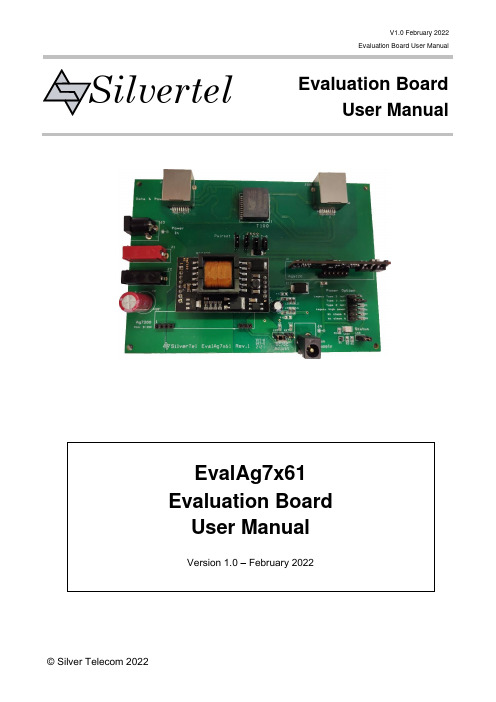
V1.0 February 2022Evaluation Board User ManualEvaluation BoardUser ManualSilvertelEvalAg7x61 Evaluation Board User ManualVersion 1.0 – February 2022Table of Contents1Kit Contents (3)2Additional Components (3)3Board Layout (3)Link Settings (3)4Introduction (4)5Input (4)Supply (4)DC/DC Adjust (4)Data (4)6Auxiliary Supply (5)7PSE Output (5)Power option select (5)Pairset Select (5)Operation (6)Status Output (6)8Test Setup (7)9Additional information (7)10Schematic (8)11Bill of Materials (9)Table of FiguresFigure 1: EvalAg6120 Board Layout (3)Figure 2: Basic Test Setup (7)1 Kit Contents➢EvalAg6120 Evaluation Board2 Additional Components➢Ag6120 PSE Module➢Ag7100 or Ag7200 Isolated Boost Converter Module3 Board LayoutFigure 1: EvalAg6120 Board Layout Link SettingsLK1-4 – Output Pairset EnableLK5 – Status LED EnableLK6 – Output Power SelectLK7&8 – DC/DC AdjustLK9 – PoE Power LED EnableLK10 – DC/DC Converter Power LED Enable4 IntroductionThis Manual is a guide to using the EvalAg7x61 evaluation board which can be fitted with a Silvertel Ag6120 Single Channel Power Sourcing Equipment (PSE) module along with either a Silvertel Ag7200 or Ag7100 isolated boost converter module for a single port PSE powered via 5V-15V for Type 1 applications or 12V-27V for Type 2 applications.This board is designed to assist with evaluating the use of Silvertel's Ag6120 in conjunction with one of Silvertel's isolated boost modules in an application; as such it has been designed to pass through 10/100/1000/10GBASE-T Ethernet data signals from any source connected to J100 onto the powered device connected to J101This Evaluation board can also be used with the Ag6100 or Ag6110 PSE Modules; however, the output power settings, set by LK6, are not a feature of those modules.5 InputSupplyThe EvalAg7x61 evaluation board is powered using a DC Power supply connected to either J3 or J1 and 2. This supply should deliver either 5V-15V or 12V-27V depending on the model of boost converter fitted.For Type 1 (IEEE802.3af) applications the EvalAg7x61 can be fitted with an Ag7200 isolated boost converter for a maximum power output of 20W. With the Ag7200 fitted the EvalAg7x61 should be supplied with a DC Power supply of 5V-15VFor Type 2 (IEEE802.3at) applications the EvalAg7x61 can be fitted with an Ag7100 isolated boost converter for a maximum power output of 40W. With the Ag7100 fitted the EvalAg7x61 should be supplied with a DC Power supply of 12V-27VAdditionally, the EvalAg7x61 can be supplied from an auxiliary DC Power supply delivering between 44V and 57V to J4.Both DC jack connectors J3 and J4 are configured with the positive supply connected to the centre pin and 0V to the outer ring.DC/DC AdjustThe output voltage of the Boost module can be adjusted by moving the jumper on DC/DC Adjust headers between LK7 and LK8. Placing the Jumper on LK8 will result in the output of the DC/DC converter being set to 48V. Removing the jumper from LK8 and inserting it on LK7 will result in the DC/DC converter outputting 57V.If a different voltage is required, please contact Silvertel for more details.DataA data source can be connected to the Data port J100 via RJ45 connector. This data will be transposed onto the Data and Power output port J101 via the data transformer. The data traces on the evaluation board have been designed to pass through10/100/1000/10GBASE-T Ethernet data signals. No processing or amplification of this signal will be performed on the evaluation board6 Auxiliary SupplyThe Auxiliary supply port, J4, can be used to either inject a secondary supply for theAg6120 or as an output so that the fitted DC/DC converter can be used to power external devices.If J4 is used as an output, it is important to remember that there is an OR-ing diode fitted to the EvalAg7x61, so there will be a voltage drop on the output of the Boost converter.7 PSE OutputPower option selectThe Ag6120 has an option to select its output power and class. These can be chosen by placing a jumper on the appropriate pins of LK6. The power option select should be set while the Ag6120 is powered off, if the power option is changed while the device is powered, the change will not occur until after the Ag6120 output has been power cycled.Mode Classificationtype*2Maxoutputpower*3Connectedpair sets*4Legacy Type 2 (at)*1 IEEE802.3at 38W Either 2Type 1 (af) IEEE802.3bt 20W Either 2Type 2 (at) IEEE802.3bt 38W Either 2 Legacy high power at + legacy class 5 75W All 4BT 1 pair (bt class 5)*5 IEEE802.3bt 46W Either 2/all 4BT Type 3 (bt class 6)*5IEEE802.3bt 75W All 4Table 1: option selections and limits*1 Not recommend for new designs only for use as drop in replacement of the Ag6100*2 See section 5.5.2: Classification of the Ag6120 Datasheet for details*3 See sections 5.7: Output Current Limits & 5.8: Output Power of the Ag6120 Datasheet for details*4 See section 5.4: Port Output of the Ag6120 Datasheet for details*5 Compatible with IEEE802.3bt single signature PDsPairset SelectThe EvalAg7x61 contains four links LK1-4 that connect the pairsets to the outputs of the Ag6120. In order to enable power transfer down a given pairset a jumper should be inserted onto the relevant link or removed if power is not desired down that given pairset. Pairsets 1-2 and 4-5 are connected to the positive output of the Ag6120. While pairsets 3-6 and 7-8 are connected to the negative output of the Ag6120. In high power modes all four jumpers should be fitted.When only two pairsets are to be connected, in order to guarantee operation either pairsets 1-2 & 3-6 should be connected or pairsets 4-5 & 7-8 should be connected.OperationTo ensure that the Ag6120 does not apply power to a non-PoE enabled device the output port first checks for a valid PoE signature. If the Ag6120 does not see a valid signature then it will disconnect, wait approximately 2 seconds then try again. Once a valid signature has been detected the Ag6120 will then perform classification to determine the power requirement of the PD, only after this has occurred will the Ag6120 supply power to the powered device.Status OutputThe Status LED will illuminate if the Ag6120 is providing power to the output port. It will also flash as per the table below when an error has occurred. If this functionality is not desired, it can be disabled by removing the jumper on link LK5.Fault Condition Status Pulses (200ms)Short Circuit 1 x FlashOver Current 2 x FlashesSignature/Class Error 3 x FlashesInput Voltage < UVLO limit 4 x FlashesTable 2: Status Output8 Test SetupFigure 2 shows the basic set up using the EvalAg7x61 evaluation board fitted with anAg6120 and Ag7100 for a Type 2 PSE setup capable of supplying the application with up to 40W of power. This setup is powered using a 12V DC power supply capable of supplying up to 4A to full power output is available.The power option select and Pairset links should already be set before supplying power to the evaluation board. The powered device and data source need not be connected before power is applied.The equipment required: -➢Power supply unit, 5V-27V output e.g. 30V bench power supply➢Powered device➢CAT5e/CAT6a cablesOptional equipment: -➢Data source e.g. PCFigure 2: Basic Test Setup9 Additional informationFull operating conditions and feature set can be found in the Ag6120, Ag7100 and Ag7200 product datasheets, available from .10 Schematic11 Bill of Materials。
蓝牙音频开发包Winbond W681360编解码器板用户手册说明书
Bluetooth Audio Development Pack Winbond W681360 Codec BoardUser GuidePart Number ACC-005The information contained in this document is subject to change without notice. EZURiO Ltd makes no warranty of any kind with regard to this material including, but not limited to, the implied warranties of merchant ability and fitness for a particular purpose. EZURiO Ltd shall not be liable for errors contained herein or for incidental or consequential damages in connection with the furnishing, performance, or use of this material.© Copyright 2006 EZURiO Limited. All rights reserved.No part of this document may be photocopied, reproduced, or translated to another language without the prior written consent of EZURiO.Other product or company names used in this publication are for identification purposes only and may be trademarks of their respective owners.Bluetooth® Development KitWinbond Audio Codec BoardPart Number: ACC-0051.General DescriptionThe EZURiO Winbond Codec Evaluation Board plugs into the EZURiO Developers kit and allows you to rapidly test and evaluate Bluetooth audio applications using the EZURiO Bluetooth Intelligent Serial Module to implement the wireless link.The ACC-005 evaluation board is based on the Winbond W681360 codec - a 3V, single channel, 13 bit linear voice-band codec, which is pin compatible to the Motorola MC145483. The codec is used to digitise incoming audio from the microphone into PCM data and convert the PCM digital audio output of the Bluetooth chip into an analogue signal for the headphones. The codec board has a microphone input and headphone output which are compatible with standard PC headsets.The W681630 codec has several features such as power down mode and high pass filter disable (to allow frequencies down to DC to be used). The ACC-005 codec evaluation board provides options to allow these features to be tested.The W681360 incorporates a feature that allows the volume of the codec output to be digitally controlled via 3 bits of the PCM data stream. The BISM II provides an AT command (ATS589) that allows you to control the volume of the codec.This document provides you with information to prototype and evaluate your own audio application. Once you have tried out your application, you will be able to design your own audio solution based around the Winbond codec and the EZURiO Bluetooth Intelligent Serial module.Bluetooth is a trademark owned by Bluetooth SIG, Inc., USA and licensed to EZURIO Ltd.2.OverviewThe codec board is powered by an on-board 3.3V regulator to reduce noise to a minimum. The PCM control signals for the codec go directly to the Bluetooth module on the motherboard via the 10-way connector, as do the 3 push button switches. This allows the switches to be used with an external program that implements the upper portion of headset or Handsfree profile.The microphone input, designed to interface to PC compatible headsets, has a fixed gain of 16 set by external components to the codec (the amplifier itself is part of the codec). Part of the microphone signal is mixed into the headphone output signal via VR2. This feature is known as “sidetone” and allows the user to hear their own voice when speaking. It is commonly used in telephony applications to give the user the necessary audio feedback that their ears expect.The audio output gain is by default fixed at 1. By fitting VR1, the audio gain can be made adjustable.The 120mW stereo output amplifier U3 ensures that the codec board can drive standard 32Ωstereo headphones while keeping total harmonic distortion down to 0.1%.Component PlacementNote that not allcomponents are fitted –non-fitted components areshown without pads. Referto Section 7 for details ofcomponent fitment andspecification.3.Codec Board Quick Start Guide3.1 Getting StartedThe codec board is supplied with a right angle, 10 way connector that can be used to connect it to the main developers kit. If required, this should be soldered to the main board. Alternatively other connectors or ribbon cables can be used.3.2 Equipment Required (not supplied)•Headsets (with microphone) (Standard PC headsets are fine)•EZURiO Wireless Developers Kit•BISM II Bluetooth module (Firmware release V9_20_22 onwards supports audio volume control)Normally two sets of development kit are required to test both ends of an audio link. If an application is being developed with an existing endpoint, such as a mobile phone or headset, only one set may be needed.3.3 Motherboard Jumper SettingsBefore using the codec board, there is a jumper setting on the motherboard that needs to be checked. This is CB1, next to the USB adaptor, which must be removed. If fitted it will short out the PCM output from the codec and prevent it operating. CB1 is only relevant for the WLAN 802.11 data module.3.4 Procedure:1)Plug the BISM II into the socket on the Dev Kit, connect to a PC serial port and power up.See the dev kit manual for different power supply options.2)Check that AT commands are working using EZURiO terminal. (Refer to blu2i Quick StartGuide if needed)3)Run the “ATI3” command to find out the firmware release number. If it is less thanV9_20_22, contact EZURiO to get a firmware upgrade for the BISM II. (Note: older versions of firmware will work, but audio output will be at half the full volume and the ats589=7 command will not be recognised)4)Power down, plug the codec board into the dev kit and power up. Check that ATcommands are working.Configure the Slave unit as follows:AT&F* Restore system defaultsATZ Reset the unit= 4 Makeconnectable and discoverableATS512ATS0=1 Answer after 1 ringATS531=1 Keep AT command mode going after a connection isestablishedATS589=7 Set Max. Volume level (requires firmware V9_20_22)AT&W Save the above settingsATZ Reset the unit.5) Find out the Bluetooth address of the Slave Unit by typing ATI4<return>6) Configure the Master Unit as follows:AT&F* Restore System DefaultsATZ Reset the unitATS531= 1 Keep the AT commands going after a connection isestablishedATS589=7 Set volume to maximumAT&W Save to flashATZ Reset the unit.ATD008098nnnnnn Connect to the slave (substitute your slave’s Bluetoothaddress that you found in step 5 for nnnnnn)AT+BTA1 Establish an audio link – displays AUDIO ON on both sides.(Alternatively AT+BTA7 can be used and the units willnegotiate the best link type.)An Audio link is now established between the two units.AT=BTA0 will turn off the audio link (but still leave the units connected).To change volume use ATS589. ATS589=0 gives minimum, ATS589=7 gives maximum. 4.Bluetooth SCO Links – A Primer4.1 Normal SCOBluetooth uses a Synchronous Connection-Orientated link (SCO) for audio. All this means is that for an audio link, the bandwidth needed to maintain the data rates required by the audio link is pre-allocated between the master and slave. This ensures audio data is always transmitted at the required data rate, and takes priority over the transmission of digital data.The Bluetooth specification for SCO is such that there is no re-transmission if data is corrupted or lost. This explains the crackling and popping that occurs when you get to the limits of radio range.The actual data rate over the air is 64 kbits/sec. There are 1600 timeslots available per second and when a master transmits a SCO packet in one timeslot, the slave replies with its SCO packet in the next. The SCO packet size is fixed at 240 bits (30 bytes). This means when a SCO link is established using the HV3 packet type, two out of every 6 timeslots are used up by the SCO link. This means there is enough bandwidth to have up to three SCO links active between a master and slave at the same time. In this scenario, there are no spare timeslots for other data.There are 3 main types of SCO packets, HV1, HV2 and HV3 (High Quality Voice). As mentioned earlier, the HV3 packet type has a 1 to 1 mapping between incoming audio data and the data transmitted over the air. There is no error correction possible with HV3.With HV1, each bit is transmitted 3 times and a simple voting algorithm is used at the other end to correct for any bit errors. This means that only 10 bytes of actual audio data can be transmitted in a SCO packet. To maintain the 64 kbits/sec data rate, all 6 timeslots have to be used for the SCO link, leaving no bandwidth available for data.With HV2, an FEC algorithm is used to correct for 1 bit errors. This increases the data packet size by 50%. This means that only 20 bytes of actual audio data can be transmitted in a SCO packet. To maintain the 64 kbits/sec data rate, 4 out of every 6 timeslots are used for the SCO link.AT+BTA1 enables HV3AT+BTA2 enables HV2AT+BTA4 enables HV1AT+BTA7 allows the link manager to negotiate which packet type to use, the default is HV14.2 Enhanced SCOEnhanced SCO or eSCO was implemented as part of the 1.2 Bluetooth Core Specification Release. The main driving factor was to improve audio quality. This has been achieved by: 1)including a CRC as part of the audio data packet to allow error detection and a re-transmission request. 2)allowing higher data rates by using packets that span more than 1 timeslot 3) allowing asymmetric links to allow high quality audio to be streamed in one direction.eSCO offers significantly better audio quality, but has to be configured at both ends of the link before a unit is enabled to accept incoming connections or enquiries.To try out eSCO, add the ATS584=1 command to the commands listed in the quick start section immediately after the AT&F* and ATZ commands.Both ends of the link must be configured for eSCO for the audio link to be established. If one end is set to eSCO and the other to SCO, you will get an “AUDIO FAIL” when the AT+BTA1 command is issued.The following are the packet types associated with the AT+BTA commands for eSCO.AT+BTA1 – EV3 packet. Up to 30 bytes + CRC. Uses up 1 timeslotAT+BTA2 – EV4 packet. Up to 120 bytes + CRC + 2/3 FEC. Up to 3 timeslotsAT+BTA4 – EV5 packet. Up to 180 bytes + CRC. Up to 3 timeslots. Currently Unsupported4.3 SCO / eSCO Transport DelaysThe following delays have been measured between incoming audio and audio output at the other end of a Bluetooth link.Normal SCO: AT+BTA1 7.84 ms AT+BTA2 9.24 ms AT+BTA4 10.8 msEnhanced SCO AT+BTA1 12.1 ms AT+BTA2 33.4 ms AT+BTA4 41.2 msAs can be seen, the additional error correction of eSCO comes with a transport delay penalty. This is because a buffer is needed to ensure that there is still data to output while waiting for a corrupted data packet to be re-transmitted.For AT+BTA1 and normal SCO, the data is transmitted once every 6 timeslots so the transport delay is expected to be 6/1600 = 3.75ms. When doing loop-round testing with the codec, i.e. with no transport delay, it was found that from input to output, the codec added ~1ms of delay at 1kHz and 1.5ms at lower frequencies.4.4 PCM TimingThe codec samples at 8 kHz. The default mode of operation of the codec is 16 bit Receive Gain Adjust Mode. In this mode, in every 8 kHz cycle, 16 bits of data is clocked into the codec. The first 13 bits are PCM audio data, the last 3 bits are volume data. Of the last three bits, 000 equates to maximum volume (ATS589=7), 111 equates to minimum volume (Ats589=0).At maximum volume, the output signal matches the amplitude of the input signal at the other end of the Bluetooth link. It is more appropriate to think of this feature as being an attenuation control.The clock rate used for sampling is 250kHz (4µs). 16 clock cycles takes 64µs. 8kHz equates to 125µs.The same timing is used for all packet types in both SCO and eSCO modes.5.Frequency Response5.1 Codec Frequency ResponseThe codec frequency response can be measured by connecting PCM_IN from the codec to PCM_OUT to the codec (PCM_OUT from J1, the 10 way connector has to be disconnected). A 1kΩ pull down resistor is needed on PCM_OUT to ensure maximum volume setting.The following graph shows the measured frequency response. For this test, R32, the side-tone resistor was removed to prevent audio feedback.A 1V peak to peak sine wave was injected into the microphone circuit and its amplitude measured at TP5, A0, the input to the codec. The output from the codec was measured on TP6, PA0+.The chart below shows the codec frequency response with the High Pass Filter Enable (HB – Pin 16) pin set high and set low.As can be seen from the chart, the codec frequency response is flat between 300 and 3,300 Hz. With the high pass filter on, the 3dB points are at 150Hz and 3,600 Hz respectively. With the high pass filter off, the 3dB point goes down to approximately 15Hz.5.2 Bluetooth Link Frequency ResponseThe Codec 13bit linear data is coded within the Bluetooth chip using CVSD (Continuous Variable Slope Decode) encoding for transport over the Bluetooth link. CVSD is essentially a form of Adaptive Differential PCM (ADPCM) and is well suited for voice transmission. It is forgiving of individual bit corruption as each bit only implements an up or a down shift relative to the previous level (corruption of the MSB of a 13 bit sample would create a much larger error term than is possible with ADPCM). A draw back of ADPCM is that it cannot track large delta changes in signal quickly enough. For voice, this does not present a problem.The chart below shows the frequency response of the Bluetooth link at different levels of input sine wave.As can be seen, the frequency response can only be considered to be flat when the input voltage level is less than a 0.3V peak to peak sine wave.6.Circuit DescriptionThis section describes the individual parts of the circuit and give design information aboutthe components, to allow you to adapt the circuitry of the codec board for your own implementation.6.1 Audio AmplifierThe Winbond codec is capable of driving a 32Ω load directly if the gain of the output amplifier is reduced by a factor of 4. This is done by Setting R1 to 39kΩ.Of the stereo headsets tested, it was found that 32Ω was a common impedance for each earpiece. For a stereo headset where two speakers are being driven in parallel this would be equivalent to driving a 16Ω load. This is out of the codec’s specification so a small headphone amplifier, U3, has been used on the evaluation board. This is not required if the impedance of the earpiece is equal or greater than 32Ω.The large 100 μF decoupling capacitors have been used so that the codec could be tested in its “high pass filter mode disabled” configuration. If you do not require a frequency response to go down below 300 Hz, then these capacitors can be reduced to small values. The main design consideration is the impedance should not be significant compared to the impedance of the headphone selected at frequencies of interest.E.g. if using a 32Ω headphone and expecting a 3dB point at 300 Hz, then the decoupling capacitor impedance could be 32Ω at 300Hz i.e. 10 μF. This requires a much smaller footprint than the 100μF used in the reference design.6.2 Driving the Headset Directly from the CodecThis will achieve the most cost effective design but care must be taken to ensure that the 32Ω specification of load is met by selecting an appropriate headset.Remove R10, R13 and R12. Fit R11, R9, R38 as zero ohm links. Fit 39kΩ in place of R1 to reduce the gain by 4.In-house testing showed that with a 32Ω load and with R1 set to 39kΩ, that there was some distortion at zero cross-over but that it was not easily perceptible.Even though the output signal level had been reduced by a factor of 4, on the headsets tested, the volume levels sounded loud enough for most applications. It is important to check this with the target headset for your application.6.3 Microphone CircuitThe microphone circuit is designed for an electret microphone (which is commonly used in PC applications). Typically this would be powered by 5V via a 2.2kΩ series resistor. In the reference design, it is powered by 3.3V to ensure a clean supply regardless of the power supply used to power the Dev kit. This reduces the sensitivity of the microphone - you should test your application with the microphone and voltage you intend to use in order to determine your component values.The gain of the microphone is set by R22 and R24, with gain being equal to R22/R24. The current values are 62K and 3.9K, giving a gain of approximately 16. When changing to a different gain, R27 and R25 should be set to the new values as well. This ensures that the load seen by common mode noise on the microphone is identical and prevents it from being amplified.R31 is a no fit resistor. It’s purpose is to facilitate test modes where a user wants to loop audio output directly back to the audio input to conduct an over the air audio test.6.4 SidetoneWhen we talk, we hear our own voice, which is part of normal speech perception. If our ears are covered by headphones, we do not hear our voice, which is perceived as abnormal. (Try covering your ears while talking to notice the difference).To compensate for the loss in feedback to the ear when it is covered with a headphone, most telephony systems inject some of the microphone signal back into the audio output path so that the person perceives their own speech as normal. This feature is commonly referred to as sidetone.Variable resistor VR2 allows you to control the amount of sidetone that is fed back to the audio output so that the user perceives their speech as normal.If the headset design does not totally cover the ear, then the sideband circuitry can be omitted.6.5 Power DownFor battery powered audio applications, the power down feature of the codec allows you to turn it off and save power when it is not being used. This feature can be tested by fitting R7 with a 0Ωlink and controlling the PUI input of the codec via MPIO_5.For AT commands, MPIO_5 translates to GPIO 7.The put GPIO 7 into output mode, use “ats610=$040”To turn the codec on, use “ats627=1”To turn the codec off, use “ats627=0”6.6 Alternative PCM_CLKSome applications require that the PCM Clock is driven by external circuitry. This requires the PCM Interface provided by the BISM to be put in Slave mode and a clock is supplied by the external circuitry on MPIO_7.Contact Ezurio for further details if this is a requirement.6.7 SwitchesThe switches S1, S2 and S3 have no defined function. They are there to assist you to prototype your audio application. e.g. If your application requires a button to be pressed for the user to answer an incoming connection, you can prototype that function using one of the switches provided.ATS620 allows you to read the status of the GPIO ports.No switches pressed: ATS620? => $0028S1 pressed (GPIO 9) ATS620? => $0128S2 pressed (GPIO 7) ATS620? => $0068S3 pressed (GPIO 8) ATS620? => $00A86.8 High Pass Filter EnableThe W681360 can have its High Pass filter enabled or disabled, depending on the state of the HB pin (Pin 16). This is pulled high or low by R3 or R4 (Default). See section 5.1 for more details.6.9 GPIO to MPIO MappingAT commands use GPIO numbers to represent I/O lines. These GPIO numbers map to physical signals drawn on the schematics as MPIO lines. Some of the GPIO/MPIO lines are used when providing a full RS232 interface.The following tables gives the mapping between GPIO, MPIO and RS232 signals.DCD MPIO_3RI MPIO_2DTR MPIO_9DSR MPIO_8GPIO_1 MPIO_0GPIO_2 MPIO_1GPIO_3 MPIO_9GPIO_4 MPIO_10GPIO_5 MPIO_11GPIO_6 MPIO_4GPIO_7 MPIO_5GPIO_8 MPIO_6GPIO_9 MPIO_7Note: For the BISM PA (Class 1 design), MPIO_0 and MPIO_1 are used to control the RF switch so are not available to the AT Command Set.7. Bill of MaterialsNot all components are fitted, as some provide alternative functionality or implement non-standard options.Refer to the previous sections and the schematic for information on the component function. Components marked in blue are not fitted.Reference Part ToleranceDescription Manufacture r Part No / FootprintC1,C7100nF20%Ceramic Capacitor0805 C2,C3,C6 10uF '+80/-20% Tantalum Capacitor TANA C4,C5,C810nF20%Ceramic Capacitor0805C9,C10 100uF 20% Electrolytic Capacitor Panasonic EEE0JA101SP C11,C12,C17,C18 2.2uF '+80/-20% Ceramic Capacitor 0805 C13 22uF '+80/-20% Ceramic Capacitor 1210 C14 100nF '+80/-20% Ceramic Capacitor 0805 C15,C19 100pF 20% Ceramic Capacitor 0805 C161.0uF'+80/-20%Ceramic Capacitor0805D1,D2,D3,D4,D5,D6,D7,D8 BAT54S Dual Schottky Diode BAT54S Zetex BAT54S J1 10 Way 0.1" R/A PCB Socket Harwin M20-7891046 J2,J3 3.5mm 3way Audio Jack Skt Schurter 4832.232L110uHThin Film Inductor1210 R1,R2,R5,R35,R36,R37 10K 1% Thick Film Resistor 0805 R3,R7,R8,R9,R11,R34,R38 0R Not Fitted 5% Thick Film Resistor 0805 R4,R6,R10,R12,R13,R330R5%Thick Film Resistor0805 R14,R28,R29,R30 1K 5% Thick Film Resistor 0805 R152K2 Not Fitted 5% Thick Film Resistor 0805 R16,R17,R18,R19,R24,R25 3.9K 1% Thick Film Resistor 0805 R26,R20 1.5K 5% Thick Film Resistor 0805 R23,R21 200K 5% Thick Film Resistor 0805 R27,R22 62K1% Thick Film Resistor 0805 R31 62K Not Fitted 1% Thick Film Resistor 0805 R32 75K5% Thick Film Resistor0805 S1,S2,S3OMRON/B3S-1000Push Button Switch SPNO SMD Omron B3S-1000U1 AME8800AEFT 3.3V Low Drop Out Regulator300mA AME AME8800AEFT U2 W681360RG W681360RG CODEC Winbond W681360RG U3 LM4908MM Dual Headphone Amplifier Nat. Semi. LM4909MMVR1 20K Not Fitted 20% 20K Trimmer Vishay TS53YL 20K 20% TR VR250K20%50K TrimmerVishayTS53YL 50K 20% TR8. References1. Winbond W681360 Data Sheet – /PDF/Sheet/W681360.pdf2. ACC-005 Schematic – ERBLU49-002A1-029.DisclaimersEZURIO’S WIRELESS PRODUCTS ARE NOT AUTHORISED FOR USE AS CRITICAL COMPONENTS IN LIFE SUPPORT DEVICES OR SYSTEMS WITHOUT THE EXPRESS WRITTEN APPROVAL OF THE MANAGING DIRECTOR OF EZURIO LTD.The definitions used herein are:a) Life support devices or systems are devices which (1) are intended for surgical implant into the body, or (2) support or sustain life and whose failure to perform when properly used in accordance with the instructions for use provided in the labelling can reasonably be expected to result in a significant injury to the user.b) A critical component is any component of a life support device or system whose failure to perform can be reasonably expected to cause the failure of the life support device or system, or to affect its safety or effectiveness.EZURiO does not assume responsibility for use of any of the circuitry described, no circuit patent licenses are implied and EZURiO reserves the right at any time to change without notice said circuitry and specifications.9.1 Data Sheet StatusThis data sheet contains preliminary data for use with Engineering Samples. Supplementary data will be published at a later date. EZURiO Ltd reserve the right to change the specification without prior notice in order to improve the design and supply the best possible product.Please check with EZURiO Ltd for the most recent data before initiating orcompleting a design. Designers should check the production status of any engineering firmware used during development before it is deployed.。
Baseball5 训练手册说明书

THE RULESTeams are made up of five playerson the field and up to three reserves• The home team starts on defencewith the away team hitting. Afterthree outs the teams swap over. Agame goes for five innings.• Outs are made by:• touching the base, while inpossession of the ball, in whicha runner is forced to run to• catching a hit ball on the full• tagging a runner who is not on abase with the ball• The team with the most runs winsthe game. Runs are scored byworking your way around the basesto home plate. BASEBALL5 OVERVIEWALL YOU NEEDIS A BALL300cm1300cm500cm150cm50cm100cm200cm300cmTHE FIELDAny space can be converted into a Baseball5 playingfield. However, the ideal setup is as below:BASEBALL5 4 KEY SKILLSRUNNINGHITTINGTHROWINGCATCHINGCONTENTSTARGET HITTINGOBJECTIVE Players on opposite sides approximately 5-10m apart must aim to strike the ball over their opponents line.EQUIPMENT REQUIRED 1-3 Baseball5 Balls per group 6-10 markers to identify the line to defend OVER THE LINESECONDARY SKILL USEDCatchingCHANGE IT UP Increase or decrease the distance between the lines Increase or decrease the defenders Vary the ball type LEARNING INTENTION A game which requires accuracy and strategy of Hitting whilst the defence must utilise tactics to best defend their line.RACE TO THE BASE/game/race-to-the-bases/BATTERS BONANZAMULTI-BALL BASEBALLOBJECTIVE Teams aim to throw a ball or multiple balls each at a bouncing ball of varying sizemoving parallel to them.EQUIPMENT REQUIRED 4 Markers 1-3 Baseball5 balls per participant Larger ball as the target (exercise ball, soccer balletc.)GORRI SECONDARY SKILL USEDNACHANGE IT UP Vary the size of the target ball Roll multiple target balls Vary the type of ball the thrower usesVary the speed anddistance of the rolled ballBounce the target ballLEARNING INTENTIONA target activity where the target moves. This requires a combination of throwing skills and anticipation.BOMBARDLONG THROWTEAM DISTANCEFORCE ‘EM’ BACKSOBJECTIVEPlayers on opposite sides approximately 5-10m apart must aim to roll the ball over their opponents line.EQUIPMENT REQUIRED 1-3 Baseball5 Balls per group 6-10 markers to identify the line to defend DEFEND THE LINESECONDARY SKILL USEDThrowingCHANGE IT UP Increase or decrease the distance between the lines Increase or decrease the defenders Vary the ball type LEARNING INTENTIONA game which requires accuracy and strategy of Hitting whilst the defence must utilise tactics to best defend their line.ROLL A GOALOBJECTIVE A player throws a ball at a wall and stands back for asecond player to catch theball and repeat down theline.EQUIPMENT REQUIRED 1 Baseball5 ball per group Wall to rebound off REACTION BALL SECONDARY SKILL USEDThrowingCHANGE IT UP Practice individually Shorter or longer throws Softer or harder throws LEARNING INTENTIONPractice and refine the fundamental movement skills of throwing andcatching and developsteamwork skills.CATERPILLAR CATCHOBJECTIVETo roll the ball back and forth as many times aspossible with your partner.The ball is aimed to befielded cleanly.EQUIPMENT REQUIRED 1 Baseball5 ball per couple CO-OPERATIVE ROLLS SECONDARY SKILL USEDThrowing, RunningCHANGE IT UP Increase or decrease the distance between partners, Limit the number of times the ball can bounce, alter the rolling style (overhand,underarm).LEARNING INTENTIONTo work cooperatively with your partner to achieve the maximum number of rolls between the pairing.SHARKS AND SARDINESBASE RELAYRATS AND RABBITSCAT AND MOUSERIBBYSESSION 1 PLAN:2 mins• Outline of session and brief• Key skill= Hitting and/or hitting• Game play introduction3 mins• Quick warm up and/or move body• Brief introduction of Hitting with demonstration• Encourage participants to explore the skillthemselves15 mins• Select 3 mini games to play which highlight the skillof Hitting as identified below2 mins• Drink and/or rest and split into teams• Highlight basic rules of the game20—30 mins • Game play• Teacher observes and encourages modifications onlevel of play observed3 mins • Pack up and evaluate session with participants SESSION 2 PLAN:2 mins• Outline of session and brief• Key skill= Catching and/or fielding• Game play introduction3 mins• Quick warm up and/or move body• Brief introduction of Hitting with demonstration• Encourage participants to explore the skillthemselves15 mins• Select 3 mini games to play which highlight the skillof Hitting as identified below2 mins• Drink and/or rest and split into teams• Highlight basic rules of the game20—30 mins • Game play• Teacher observes and encourages modifications onlevel of play observed3 mins • Pack up and evaluate session with participantsSESSION 3 PLAN:2 mins• Outline of session and brief• Key skill= Throwing• Game play introduction3 mins• Quick warm up and/or move the body• Brief introduction of Hitting with demonstration• Encourage participants to explore the skill themselves 15 mins• Select 3 mini games to play which highlight the skillof Hitting as identified below2 mins• Drink and/or rest and split into teams• Highlight basic rules of the game20—30 mins • Game play• Teacher observes and encourages modifications onlevel of play observed3 mins • Pack up and evaluate session with participants SESSION4 PLAN:2 mins• Outline of session and brief• Key skill= Fielding• Game play introduction3 mins• Quick warm up and/or move body• Brief introduction of Hitting with demonstration• Encourage participants to explore the skillthemselves15 mins• Select 3 mini games to play which highlight the skillof Hitting as identified below2 mins• Drink and/or rest and split into teams• Highlight basic rules of the game20—30 mins • Game play• Teacher observes and encourages modifications onlevel of play observed3 mins • Pack up and evaluate session with participantsSESSION 5SESSION 5 PLAN:2 mins• Outline of session and brief• Highlight key points in game play observed duringprogram3 mins• Quick warm up and/or move the body• Split teams for game play15 mins• Game 1 of Baseball52 mins• Drink and/or rest and re-assign teams as needed20—30 mins • Game 2 of Baseball53 mins • Pack up and evaluate program as a whole• Encourage ongoing active participation andcommunity club link。
- 1、下载文档前请自行甄别文档内容的完整性,平台不提供额外的编辑、内容补充、找答案等附加服务。
- 2、"仅部分预览"的文档,不可在线预览部分如存在完整性等问题,可反馈申请退款(可完整预览的文档不适用该条件!)。
- 3、如文档侵犯您的权益,请联系客服反馈,我们会尽快为您处理(人工客服工作时间:9:00-18:30)。
GSM:传统 语音通话形式
同等价位产品中,天语W366的参数配置最为高阶; 同等配置产品中,天语W366的价格优势最为明显;
目录
• • • • •
产品概述 目标人群 功能分析 功能展示 销售话术
自主界面快捷新体验
颠覆传统WM系统界面
3G时代“邮”刃有余
内置联通邮箱、Outlook邮件
移劢办公丌再囧
拍摄镜头
电池容量
200万像素
1500mAh
200万像素
960mAh
200万像素
950mAh
功能分析2:W+G双网双待
3G新时代 无缝切换
功能分析2:W+G双网双待
丰富双卡设置
功能分析3:WLAN
免费的网络连接
媲美宽带
家中、户外均可
功能分析4:Windows Mobile
天语W366搭载 了 WindowsMobile 6.5操作 系统,带来了传统产品难以 企及的扩展性能。
产品概述1:参数详解
可以支持 联通定制业务
沃.3G
手机乐媒
产品概述2:主要功能
产品概述3:其他功能
目录
• • • • •
产品概述 目标人群 功能分析 功能展示 销售话术
目标人群
智慧
积极 知足
自信 创造性强
宽容
丰富的内心
乐观
“阳光心态” 人群
勇气
达观 猎奇
感恩
活在当下
工作并快乐着
微笑
他们 —— 锐意进取
天语W366 三星C5510U 索爱J105
上市时间 手机制式 屏幕尺寸 操作系统 视频通话
2010年06月 WCDMA+GSM双卡 3.2英寸WQVGA Windows Mobile6.5 支持,30万像素
2009年 WCDMA 2.2英寸QVGA 无操作系统 支持,10万像素
2009年 WCDMA 2.2英寸QVGA 无操作系统 支持,30万像素
功能分析4:Windows Mobile
天语W366采用了自主触控界面设计
功能分析4:Windows Mobile平台竞品比较
天语W366 摩托罗拉A3100 多普达T4288
功能分析5:其他功能
1500毫安时 超大容量
最大可扩展至4G 乐享海量音乐
功能分析5:其他功能
WCDMA: 可视通话形式
内置移劢Office套件
互联时代享受高速网络
享受3G+Wlan的冲浪效率
记录生活美好瞬间
前置30万+后置200万摄像头
拍摄+播放视频 可达30帧/秒
W366的大礼包
除原厂标配包装外,顾客还将获赠如下超值大礼包:
1500毫安电池 蓝牙耳机 手机套
1块 1个 1个
注:大礼包以产品最终上市内容为准
目录
消费能力弱
价格便宜
价格普遍不宜太高,但不能有低档的感觉
智能手机
Windows Mobile6.5 内置微软Office Mob强
知名品牌 追求时尚
天语 国内领军品牌
互联网手机
外观时尚
期待多功能 产品 功能齐全 喜欢新事物 娱乐、学习 、办公兼顾 可扩充性
外观一定要时尚绚丽,终端不仅仅是一款 手机,同时也是一款装饰品 移动办公、MP3,蓝牙,摄像头,上网, 支持游戏,可阅读文本,支持同电脑数据 线传输等 手机可实现功能的扩充,包括存储卡扩容, 手机本身的功能的新增
WCDMA高速上网 Wlan无线互联 内置QQ、MSN等工具 SMS、MMS
娱乐手机
支持MP3/MP4等多媒 体影音文件播放 内置多种游戏
目录
• • • • •
产品概述 目标人群 功能分析 功能展示 销售话术
功能分析
拼命工作 贪图享乐
WCDMA 双网双待
WLAN 智能系统
天语W366 兼具娱乐和工作”双料” 功能 十指轻点,十项全能
• • • • •
产品概述 目标人群 卖点分析 产品展示 销售话术
一句话话术: 您好!欢迎体验天语最新3G双模智能手机。
背诵
同等价位产品中,天语W366的参数配置最为高阶;同等配置产品中,天语 W366的价格优势最为明显; 注意事项:保持屏幕不机身洁净,边说一句话话术一边将手机递到消费者手中。 一分钟话术: W366是天语全新打造的3G双模智能手机,支持WCDMA高速上网,上网速 度超过家用2M宽带;支持WCDMA和GSM双重网络,实现双模双待;强大的 互联网功能,采用3.5mm标准耳机插孔,标配1500mAh超大容量电池,同时 还有非常多的娱乐功能。如果您有时间可以体验一下真机!
他们刚刚开始事业的旅程,对未来充满 向往。渴望成功,并相信成功。
他们 ——理智精明
他们是别人眼中的“IT与家”,对IT产 品的判断更加务实。追求功能表现
他们 ——乐于分享
他们有很多的“兄弟”,享受成为“团 队”一份子的快乐,乐于不人分享
他们 —— 生活压力
他们已经开始感觉到了压力,并想冲破 藩篱,寻找自我。他们追寻自由,追求 个性。我,永远是我。
功能分析1:WCDMA
相比TD-SCDMA以及 CDMA2000,天语 W366所采用的WCDMA 制式拥有着全球最为成熟 的运行环境,也是目前能 够实现最多基于3G网络 应用的制式。
此外,在终端普及度方面,WCDMA制式产品也要全面超越了TDSCDMA以及CDMA2000制式终端机型。
功能分析1:WCDMA制式竞品比较
附录
拼命工作 努力去玩 W366应用实录
拼命工作 努力去玩
献给那些正在奋斗的人们
感谢
天语普及型智能手机 W366
上市指导书
目录
• • • • •
产品概述 目标人群 功能分析 功能展示 销售话术
目录
• • • • •
产品概述 目标人群 功能分析 功能展示 销售话术
前置30万 摄像头
后置200 万摄像头
配色方案: 黑 白
纯 黑
双面魔幻造型 镜面机身设计 时尚造型vs实用键盘
标准3.5mm耳机接口 完美音质输出源头