2SJ319L-E中文资料
IXYS DS99002 高电压双极性MOSFET数据手册说明书

© 2003 IXYS All rights reserved DS99002(01/03)Symbol Test Conditions Maximum Ratings V DSS T J = 25°C to 150°C500V V DGR T J = 25°C to 150°C; R GS = 1 M Ω500V V GS Continuous ±30V V GSM Transient ±40V I D25T C = 25°C40A I DM T C = 25°C, pulse width limited by T JM 160A I AR T C = 25°C40AE AR T C = 25°C 50mJ E AS 2.5mJdv/dt IS ≤ I DM , di/dt ≤ 100 A/µs, V DD ≤ V DSS , 20 V/ns T J ≤ 150°C, R G = 2 ΩP D T C = 25°C500WT J -55 to +150°C T JM 150°C T stg -55 to +150°C T L 1.6 mm (0.063 in) from case for 10 s 300°CM d Mounting torque1.13/10 Nm/lb.in.WeightTO-247 6g TO-268 4gN-Channel Enhancement ModeAvalanche Rated, Low Q g , High dv/dtFeaturesz IXYS advanced low Q g process zLow gate charge and capacitances - easier to drive - faster switchingzInternational standard packages z Low R DS (on)zRated for unclamped Inductive load switching (UIS)rated zMolding epoxies meet UL 94 V-0flammability classificationAdvantagesz Easy to mount z Space savings zHigh power densitySymbol Test ConditionsCharacteristic Values(T J = 25°C, unless otherwise specified)min.typ.max.V DSS V GS = 0 V, I D = 250 µA 500V V GS(th)V DS = V GS , I D = 4 mA 2.54.5V I GSS V GS = ±30 V DC , V DS = 0±100nA I DSS V DS = V DSS T J = 25°C25µA V GS = 0 VT J = 125°C1mA R DS(on)V GS = 10 V, I D = 0.5 I D250.14ΩPulse test, t ≤ 300 µs, duty cycle d ≤ 2 %TO-247 AD (IXFH)G = Gate D = Drain S = Source TAB = DrainHiPerFET TMPower MOSFETs Q-ClassTO-268 (D3) ( IXFT)(TAB)GSV DSS =500 VI D25= 40 A R DS(on)=0.14 Ωt rr ≤ 250 nsIXFH 40N50Q IXFT 40N50Q(TAB)Disclaimer Notice - Information furnished is believed to be accurate and reliable. However, users should independently evaluate the suitability of and test each product selected for their own applications. Littelfuse products are not designed for, and may not be used in, all applications. Read complete Disclaimer Notice at /disclaimer-electronics.。
PR 412091 三相电能测量仪产品说明书

PR_412091.xlsxLG-412091COMMUNICATION PROTOCOL GENERAL MODBUS TABLE ORGANIZATIONStarting Address of the Group Registers (Dec)Starting Address of the GroupRegisters (Hex)System Version(Release)System Version(Build)Group Name (Text)Group Code(Hex)Group Complexity(Hex)Group Version(Hex)000119Modbus settings00 011001 00 409610000119External input10 001001 00 2048050000119Three-phase Electric Measurement71 03 4001 00 2048050000119Measure configuration71 03 4001 00 2969674000119Pulse measurement 74 001001 00MODBUS PROTOCOL DETAILSFunction Code (Dec)Exception Codes (Dec)Data Encoding2 (Read Discrete Inputs)1, 2, 3"Big Endian" (most significant byte first)1 (Read Coils)1, 2, 3"Big Endian" (most significant byte first)5/15 (Write Single/Multiple Coils)1, 2, 3"Big Endian" (most significant byte first)4 (Read Input Registers)1, 2, 3"Big Endian" (most significant byte first)3 (Read Holding register)1, 2, 3"Big Endian" (most significant byte first)6/16 (Write Single/Multiple Holding register)1, 2, 3, 4"Big Endian" (most significant byte first)MODBUS OVER SERIAL DETAILSPhysical Layer Trasmission Modes Device Addressing Baud Rates (bit/s)Data BitsData bitstrasmissionsequenceParity Stop Bitsstandard EIA/TIA 485 (RS-485) two-wireconfiguration RTU1÷255programmable(4800, 9600, 19200,38400)8Least significantbit firstprogrammable(NONE, EVEN, ODD)1MASTER/SLAVE COMMUNICATION TIMINGTimer Description Timer Value (msec)Inter-character time-out< 1,5 character timesResponse delay (from master request)programmable ( 0 ÷ 99 ms )Delay Time (between two master trasmissions)-REFER ALSO TO:- MODBUS over serial line specification and implementation guide V1.02- MODBUS APPLICATION PROTOCOL SPECIFICATION V1.1bNOTE:File and printed copies of this document are not subject to document change control.LG-412091Register Number RegisterAddress(Dec)RegisterAddress(Hex)Dimension[bit]Description NoteReadFunctionCodes (Dec)Data Storing4097409610001External input4097409610001Current active tariff See Note 12Note 10: Tariff 11: Tariff 2LG-412091Register Number RegisterAddress(Dec)RegisterAddress(Hex)Dimension[bit]Description NoteReadFunctionCodes (Dec)WriteFunctionCodes (Dec)Data Storing(no COILS availables)Number Address(Dec)Address(Hex)[word]PositionDescription Type Scale Unit Range Note FunctionCode (Dec)Storing20481204805000257Three-phase Electric Measurement204812048050002Phase 1 Current Value (R)unsigned integer1mA See Note 14 204832048250022Phase 2 Current Value (S)unsigned integer1mA See Note 14 204852048450042Phase 3 Current Value (T)unsigned integer1mA See Note 14 2048720486500623RESERVED (all return "8000h")2051020509501D21-N Voltage unsigned integer1mV See Note 14 2051220511501F22-N Voltage unsigned integer1mV See Note 14 2051420513502123-N Voltage unsigned integer1mV See Note 14 2051620515502321-2 Voltage unsigned integer1mV See Note 14 2051820517502522-3 Voltage unsigned integer1mV See Note 14 2052020519502723-1 Voltage unsigned integer1mV See Note 14 2052220521502916RESERVED (all return "8000h")205382053750391Three-phase frequency unsigned integer0,01Hz See Note 14 2053920538503A2Three-phase Active Power signed integer0,01W See Note 24 2054120540503C2Three-phase reactive power signed integer0,01var See Note 24 2054320542503E2RESERVED (all return "8000h")205452054450402Threee-Phase Apparent Power unsigned integer0,01VA See Note 14 205472054650422RESERVED (all return "8000h")205492054850441Three-phase Power Factor (PF)signed integer0,01See Note 24 205502054950451RESERVED (returns "8000h")205512055050461Power Factor (PF) sector unsigned integer See Note 54 205522055150472Phase 1 Active Power signed integer0,01W See Note 24 205542055350492Phase 2 Active Power signed integer0,01W See Note 24 2055620555504B2Phase 3 Active Power signed integer0,01W See Note 24 2055820557504D2Phase 1 Reactive power signed integer0,01var See Note 24 2056020559504F2Phase 2 Reactive power signed integer0,01var See Note 24 205622056150512Phase 3 Reactive power signed integer0,01var See Note 24 205642056350536RESERVED (returns "8000h")205702056950592Phase 1 Apparent Power unsigned integer0,01VA See Note 14 2057220571505B2Phase 2 Apparent Power unsigned integer0,01VA See Note 14 2057420573505D2Phase 3 Apparent Power unsigned integer0,01VA See Note 14 2057620575505F17RESERVED (returns "8000h")205932059250702Positive Three-phase Active Energy unsigned integer0,01kWh See Note 14Y 205952059450722Negative Three-phase Active Energy unsigned integer0,01kWh See Note 14Y 205972059650742RESERVED (returns "80000000h")205992059850762Positive Three-phase Reactive Energy unsigned integer0,01kVarh See Note 14Y 206012060050782Negative Three-phase Reactive Energy unsigned integer0,01kVarh See Note 14Y 2060320602507A2RESERVED (returns "80000000h")2060520604507C2Positive Three-phase Active Energy (Tariff 1)unsigned integer0,01kWh See Notes 1 and 64Y 2060720606507E2Negative Three-phase Active Energy (Tariff 1)unsigned integer0,01kWh See Notes 1 and 64Y 206092060850802Positive Three-phase Reactive Energy (Tariff 1)unsigned integer0,01kVarh See Notes 1 and 64Y 206112061050822Negative Three-phase Reactive Energy (Tariff 1)unsigned integer0,01kVarh See Notes 1 and 64Y 206132061250842Positive Three-phase Active Energy (Tariff 2)unsigned integer0,01kWh See Notes 1 and 64Y 206152061450862Negative Three-phase Active Energy (Tariff 2)unsigned integer0,01kWh See Notes 1 and 64Y 206172061650882Positive Three-phase Reactive Energy (Tariff 2)unsigned integer0,01kVarh See Notes 1 and 64YNumber Address (Dec)Address (Hex)[word]PositionDescriptionType Scale Unit Range NoteFunction Code (Dec)Storing2061920618508A 2Negative Three-phase Reactive Energy (Tariff 2)unsigned integer0,01kVarhSee Notes 1 and 64Y2062120620508C 105RESERVED (returns "8000h")207262072550F51Phase shift between V1 - V2unsigned integer 0,1°See Note 34207272072650F61Phase shift between V2 - V3unsigned integer 0,1°See Note 34207282072750F71Phase shift between V3 - V1unsigned integer 0,1°See Note 34207292072850F81Phase shift between U12 - U23unsigned integer 0,1°See Note 44207302072950F91Phase shift between U23 - U31unsigned integer 0,1°See Note 44207312073050FA 1Phase shift between U31 - U12unsigned integer 0,1°See Note 44207322073150FB 1Phase shift between I1 - I2unsigned integer 0,1°See Note 14207332073250FC 1Phase shift between I2 - I3unsigned integer 0,1°See Note 14207342073350FD 1Phase shift between I3 - I1unsigned integer 0,1°See Note 14207352073450FE 1Phase shift between V1 - I1unsigned integer 0,1°See Note 14207362073550FF 1Phase shift between V2 - I2unsigned integer 0,1°See Note 14207372073651001Phase shift between V3 - I3unsigned integer0,1°See Note 14Note 6Only if the input acts as "Tariff selector"Note 7Only if the input acts as "Pulse measurement"Expressed on "numeric coding"; without mark (fixed more significant bit = 0);Only with 3N-3E Note 4Expressed on "numeric coding"; without mark (fixed more significant bit = 0);Only with 3-3E Note 50: power factor = 11: inductive 2: capacitive Expressed in "numeric coding"; with mark (more significant bit = mark);Note 1Expressed on "numeric coding"; without mark (fixed more significant bit = 0);Note 2Note 3Number Address(Dec)Address(Hex)[word]Bit Position Description Type Scale Unit Range Note FunctionCodes (Dec)FunctionCodes (Dec)Storing1001Modbus settings1001Protocol type unsigned integer See Note 1316Y 4097409610001External input4098409710011Configuration of external input unsigned integer See Note 2316Y 20481204805000223Measure configuration204812048050001Measurement System Features unsigned integer See Note 3316Y 204822048150011Phase Currents Transformation Ratio (KTA)unsigned integer11See Note 7316Y 204832048250022RESERVED (all return "8000h")204852048450041Voltage Transformation Ratio (KTV)unsigned integer0,01100See Note 7316Y 204862048550052Calculation Settings Requirement unsigned integer See Note 4316Y 2048820487500771RESERVED (all return "8000h")2055920558504E2Partial Positive Three-phase Active Energy unsigned integer0,01kWh See Note 5316Y 205612056050502Partial Negative Three-phase Active Energy unsigned integer0,01kWh See Note 5316Y 205632056250522RESERVED (all return "8000h")205652056450542Partial Positive Three-phase Reactive Energy unsigned integer0,01kvarh See Note 5316Y 205672056650562Partial Negative Three-phase Reactive Energy unsigned integer0,01kvarh See Note 5316Y 2056920568505868RESERVED (all return "8000h")2063720636509C2Total Active Power Requirement (MD)unsigned integer0,01W See Note 7316 2063920638509E2Maximum Total Active Power Requirement (PMD)unsigned integer0,01W See Note 5316Y 206412064050A032RESERVED (all return "8000h")206732067250C02Maximum Total Active Power Requirement Tariff 1 (PMD T1)unsigned integer0,01W See Notes 5 and 9316Y 206752067450C24RESERVED (all return "8000h")206792067850C62Maximum Total Active Power Requirement Tariff 2 (PMD T2)unsigned integer0,01W See Notes 5 and 9316Y 206812068050C816RESERVED (all return "8000h")206972069650D81Run hour meter threshold unsigned integer0,01%0 ÷ 5000316Y 206982069750D92Run hour meter (TOT)unsigned integer s See Note 6316Y 207002069950DB2Run hour meter (Tariff 1)unsigned integer s See Notes 7 and 9316Y 207022070150DD2Run hour meter (Tariff 2)unsigned integer s See Notes 7 and 9316Y 296972969674004Pulse measurement296972969674001Measurement unit input unsigned integer See Note 8316Y 296982969774011Pulse weight input unsigned integer0,01 1 ÷ 10000316Y 296992969874022Pulse pulse input unsigned integer0,01See Note 5316YNote 10: Standard MAP;1: Basic MAP.Note 2Bit 6 = 0: the input acts as "Tariff selector";Bit 6 = 1: the input acts as "Pulse measurement".Note 3BYTE1 (MSB):"33": Three-pahse system without neutral 3-3E;"34": Three-pahse system with neutral 3N-3E.BYTE0 (LSB):"00" [default]: if the active power flows in the normal/indicated direction (“upstream to downstream” or depending on the polarity indicated for theconnection );Note 4WORD0 (LSW): calculation method1: "sliding block interval"WORD1 (MSW): calculation window (value in [min] (5, 8, 10, 15, 20, 30, 60), “default”=15)Note 5This register is writable, but only with zeroNote 6This register is writable, but only with zero. Writing this register you will delete also the two tariffs values. Note 7Writing this register has no effect.Note 80 : Wh (default)1 : kWh2 : MWh3 : Varh4 : kVarh5 : MVarh6 : VAh7 : kVAh8 : MVAh9 : m310 : km311 : Mm312 : Nm3 (normal meter3)13 : kNm314 : MNm315 : J16 : kJ17 : MJ18 : cal19 : kcal20: g21: Kg23: TNote 9Only if the input acts as "Tariff selector"。
新能源柴油发电机组技术规格书

新能源柴油发电机组技术规格书一、设备名称:柴油发电机组1套1.1 柴油机:1套(国内一线品牌)1.2 交流发电机:1套(国内一线品牌)1.3 全自动控制柜(含市电全自动切换开关):1套(国内一线品牌)1.4 室外用静音箱(含底座油箱):1套1.5 机组安装调试工程:1项二、主要技术参数:2.1.柴油发电机组技术指标要求2.1.1机组常用发电功率≥300KW(常载)2.1.2频率:50Hz2.1.3功率因数:0.82.1.4输出电流:560A2.2机组电气性能2.2.1电压稳态调整率≤±1%2.2.2电压瞬态调整率:+20~-10%2.2.3电压稳定时间≤1S2.2.4电压波动率≤±0.5%2.2.5频率稳态调整率≤±1%2.2.6频率瞬态调整率≤+10%2.2.7频率稳定时间≤3S2.2.8频率波动率≤±0.5%2.2.9输出线电压波形畸变率±52.2.10三相不对称负载下的线电压偏差±52.2.11柴油发电机组出厂时,已进行整机100%全性能试验,提供测试报告。
2.2.12机组应采取良好的减振措施,满载运行时,其纵向最大振幅不大于0.5mm2.2.13机组在负载过载10%时,应能正常运行30分钟。
2.2.14机组不得有漏水、漏油、漏电现象。
2.2.15机组应能使用轻质柴油为燃油及机油为润滑油。
2.2.16发动机与发电机采用刚性直接联接,发动机与底座之间装配内置式减震垫。
2.2.17全部的装置、必要的装置,都装载在底盘上。
2.3柴油机2.3.1柴油机额定功率≥300KW2.3.2柴油机工作转速:1500r/min左右2.3.3柴油机冷却方式:水冷2.3.4启动方式:电启动2.3.5转速调节方式:电子调速2.3.6结构型式:直列6缸2.3.7缸径行程:厂家提供2.3.8四冲程、水冷、涡轮增压,数码式自动调速功能;2.3.9封闭式循环水冷却;2.3.10选用转速为1500r/min的电启动柴油发动机,装有电子调速稳压装置;2.3.11柴油发动机额定功率和交流发电机额定功率匹配比,不小于1.2:1;2.3.12柴油机应采用电预加热装置;2.3.13风冷机组配备冷却风扇及水箱。
邯郸锦绣花苑小区低压配电柜技术规范书

锦绣花苑10kV配电工程0.4Kv GGD3型固定式低压交流开关柜技术规范书编写:荣盛发展邯郸分公司2009年9月锦绣花苑10kV配电工程0.4Kv GGD3型固定式低压交流开关柜技术规范书批准:审定:校对:编写:目录1总则 1 1.1 招标需知 1 2执行标准 1 3使用条件 2 3.1 环境条件 23.2 系统条件 24.技术参数5.结构 5 5.1 基本要求 5 5.2 铭牌 6 5.3 断路器 7 5.4 互感器 7 5.5 隔离开关 75.6 测量仪表及辅助回路 76.试验 8 6.1 实验项目 86.2 实验要求 87.包装运输 9 7.1 包装 9 7.2 标志 97.3 运输及保管 108.供货范围 109.技术服务 1010.附表 101.总则1.1 招标需知1.1.1 本技术规范书仅适用于“锦绣花苑 10KV 配电工程”,提出了招标方订购10kV户内固定式交流金属封闭开关柜的技术要求。
主要包括设备的使用条件、主要技术参数、结构、性能、试验、包装、运输及所需技术资料等方面的内容。
1.1.2 本技术规范书是按有关标准提出的技术要求,并未对一切技术细节作出规定,也未充分引述有关标准的条文,投标方应按有关标准提供符合本规范书技术规范的优质产品。
1.1.3 本技术规范书所使用的标准及规定的条款如遇与投标方所执行的标准不一致时,投标方应提供执行标准原文,若使用外文应同时提供中译本。
文本经协商确认后,按较高标准执行。
1.1.4 卖方应提供相应产品的形式试验报告和生产资质证书,否则将作废标处理。
1.1.5如果投标人没有以书面形式对本规范书的条文提出异议,则意味着投标人提供的设备完全符合本规范书的要求。
如有异议,不管是多微小,都应填写《技术条款差异说明表》加以详细描述。
1.1.6本技术规范书经供需双方确认签字后作为订货合同的技术附件,与合同正文具有同等的法律效力。
2执行标准GB156 《标准电压》GB7251 《低压成套开关设备》IEC439 《低压成套开关设备和控制设备》GB/T14048.1 《低压开关设备和控制设备总则》GB14048.2 《低压开关设备和控制设备低压断路器》GB/T16935.1《低压系统内设备的绝缘配合:第一部分:原理、要求和试验》 DL/T597 《低压无功补偿器订货技术条件》GB12747-2004《标称电压1KV及以下交流电力系统用自愈式并联电容器》GB/T2900.18 《电工术语低压电器》GB4208 《外壳防护等级(IP代码)》GB191 《包装储存标志》3使用条件3.2 系统条件4.技术参数投标人应认真逐项填写技术参数响应表中投标人保证值,不能空格,也不能以“响应”二字代替,不允许改动招标人要求值。
9-2和3极联接器说明书

A201, A251 Size 9 2 and 3 Pole Contactors, Non-reversing and ReversingFig. 1 Front Connected 3 Pole ContactorFig. 2 Rear Connected 3 Pole ContactorFig. 3 Dimension Drawings (Dim. in inches)Size 9 Contactors are designed for the control of inductive or non-inductive loads at voltages between 24 and 600, AC. The units are suitable for mount-ing on either steel or insulated panels. All parts are front removable. Contac-tors should be protected against short circuits by branch circuit protective devices selected in accordance with the National Electrical Code (NEG).Two pole contactors have the same current ratings as 3 pole devices but are not suitable controlling 3 phase motors.This industrial type control is designed to be installed, operated, and main-tained by adequately trained workmen. These instructions do not cover all details, variations, or combinations of the equipment, its storage, delivery, installation, check-out, safe operation, or maintenance. Care must be ex-ercised to comply with local, state, and national regulations, as well as safety practices, for this class of equipment.CONTACTOR RATINGS - 3 POLE CONTACTORS Continuous Current Three Phase Horsepower at:Open 2500AEnclosed 2250A230 Volts 800460 Volts 1600Three Phase Switching at:T ransformers Capacitors 208 Volts 240 Volts 480 Volts 600 Volts337 KVA 392 KVA 783 KVA 975 KVA575 KVAR 655 KVAR 1325 KVAR 1670 KVARCONTACTOR RATINGS - 2 POLE CONTACTORSSingle Phase Switching at:T ransformer Rating120 Volts 240 Volts 480 Volts 600 Volts112 KVA 225 KVA 450 KVA 562 KVAA201 And A251, Size 9 Contactors Coils.Each size 9 contactor has a single winding ,DC coil rated such that it canbe supplied from a full wave rectifier operating at 120 volts AC. As theoperating magnet armature approaches its sealed position a late-break,normally-closed auxiliary contact opens and introduces a resistor into thecoil circuit reducing the voltage across the coil to approximately 17 voltsDC. See Figures 4 and 5 for control circuits. The control relays (CR) shownin Figures 4 and 5 are not included with the contactor. The 120 volt, 60hertz control power transformer or separate supply must be capable ofsupplying 2100 VA inrush and 350 VA (350 Watts) continuously while main-taining an AC voltage of not less than 115 volts to the rectifi er, in additionto supplying control relays and other control circuit devices such as indicat-ing lights. Overcurrent protection for the control circuit (#12 AWG) shouldbe provided at the source of control voltage in accordance with the NEC.The coils have been designed to operate at high temperatures, and areinsulated to meet such service. The operator should not be alarmed to fi ndthe coils hot to the touch.Changing Coils.To remove and replace the operating coil, proceed as shown below. Item( ) references are to Fig. 6. Tightening torque values are shown in Table 1.1. Turn all power OFF.2. Remove the arc quencher (1) adjacent to the coil.3. Remove the coil (2) leads and adjacent phase barrier (3).4. Remove the two screws holding the auxiliary contact support bracket(4) to the lower horizontal brace. Let the attached leads support theauxiliary contact assembly (5).5. Remove the armature stop (6), magnet pole face (7), shim retainer(8), and stop bracket (9), by removing the five 1/2-13 cap screws andtwo spacers (10). The armature (11) can now rotate out of the way tofacilitate coil removal from the magnet core.6. Replace the coil.7. Remount the retainer, shim and pole face, ensuring that the shim islocated between the magnet core and the pole face. Tighten the capscrew holding the pole face to the core.8. Attach the armature stop bracket and shorter spacer to the left sideof the pole face. Insert the longer spacer between the pole face andend plate. Rotate the armature forward and attach the armature stop.9. Torque the five cap screws to 100 pound-feet.10. Reattach the auxiliary contact assembly to the lower brace.11. Attach the coil leads.12. With the power circuit disconnect open, energize the coil circuit.13. Check to confirm that, with the armature sealed:(a) The armature is centered on the pole face within 1/32 inch.(b) There is approximately 1/16 inch clearance between the armatureand lower pole face.(c) The electrical interlocks’ plunger can be depressed an additional1/16 inch before bottoming out.Loosen and adjust parts as necessary.14. Attach the phase barrier and arc quencher.Fig. 4 Non-reversing Control CircuitFig. 5 Reversing Control Circuit2Instructions Leafl et IL16978Effective October 2011A201, A251 Size 9 2 and 3. Pole Contactors,Non-reversing and Reversing EATON CORPORATION Contact Inspection And Replacement.To inspect contacts and replace them proceed as shown below. Item refer-ences are to Figure 6. Contact replacement is necessary when the contactovertravel, measured at point X, Figure 7, has been reduced to 3/32 inch.1. T urn all power OFF .2. Remove arc quenchers (1) and phase barriers. (3)3. Remove moving contact shunt bolts (12).4. Remove clamps (13) holding moving contact assembly to the shaftand remove assembly from shaft.5. Remove stationary contact bolts (14).6. Install new stationary contacts and bolts. Refer to Table I for boltdriving torques.7. Install new moving contact assembly on the shaft and bolt shuntends to contacts.8. See page 4 for contact adjustment.9. Replace arc quenchers and phase barriers.Operation And Maintenance.The arc quenchers must be in place when the contactor interrupts a circuit.Each arc quencher is held in place by two screws located at the top. Two pins projecting from the stationary contact support engage notches in the lower rear sides of the arc quencher and serve to position it. A notch mold-ed in the arc quencher cap engages the support plate to hold the arc box in position while the two screws are being assembled. The legs of the arc quencher grid plates are protected from the arc by ceramic barriers, which must be in place when the contactor is operated.Reversing Contactors.Reversing contactors consist of two contactors with power poles intercon-nected by buswork, normally-closed electrical interlocks, and a Type M-52 mechanical interlock.Fig. 6 Cutaway View3Instructions Leafl et IL16978Effective October 2011A201, A251 Size 9 2 and 3. PoleContactors,Non-reversing and ReversingEATON CORPORATION A201 And A251 Size 9 Contactors.Mechanical InterlockThe Type M-52 mechanical interlock is used when a pair of contactors must be mechanically protected against the closing of one when the other is already closed. The two contactors may be exactly alike or may be mixed as to size or number of poles. They must be mounted one below the other, as shown in Figure 3.The Type M-52 mechanical interlock consists of a lower operating lever, a tie rod, and an operating pin secured to the top of the armature of the lower contactor and to the bottom of the armature of the upper contactor. With the upper contactor open and the lower contactor closed, adjust the tie rod so that the lower operating lever clears the operating pin by 1/4 inch. Tighten the tie rod lock nuts. Then make sure, by alternate manual closing of fi rst one contactor, then the other, that interlocking action is correct.Auxiliary Contacts - L64Two double-circuit L64 auxiliary contacts (electrical interlocks) are supplied with each contactor in addition to the normally-closed, late-break contact that introduces resistance into the coil circuit. One normally-open circuit can be used in the coil holding circuit of the control relay that supplies voltage to the contactor coil and one normally-closed circuit can be used for electrical interlocking. The second double-circuit auxiliary is available for circuit monitoring.Contact Adjustment.Make sure that all contact pairs touch simultaneously within 1/32 inch. Suffi cient adjustment can generally be obtained by a selective tightening of the two bolts securing the shaft clamp (13) to the moving contact bracket (Figure 7), tightening one more than the other to produce a slight rota-tion of the assembly on the shaft (17). When adjusted, the contact air gap should be 3/4 inch with the armature in the fully open position. A gap of 3/16 to 7/32 inch, measured at Point X, Figure 7, is typical with newly in-stalled contacts when the armature is in the fully closed position.Contact Spring Forces.Measure the contact force at the top of the moving contact inlay and in line perpendicular to the moving contact (15). The contactor employs multiple contacts in parallel for each pole. The forces given below are for each con-tact. See Figures 6 and 7.To measure the initial force; exert a measured pull with the contactor open until the shank of the moving contact just leaves its stop.To measure the fi nal force, keep the armature (11) fully seated against the magnet pole face (7) and exert a measured pull until the contacts just startto separate. Contact forces with new contacts should be as follows:L64 CONTACT RATINGS(1 normally-open, 1 normally-closed) - A600Part Number Volts Make Break843D943G0424-120 AC120-600 AC24-600 DC60 A7200 VA200 VA6 A720 VA200 VATABLE I RECOMMENDED DRIVING TORQUELocation (Qty.)Driving T orque(LB/IN)Fig. 6Item NumberWire LugsLug Mtg. ScrewsArc Quencher Scr.Shaft ClampCap ScrewsSta. Contact boltShunt boltControl CircuitElectrical Connections(8/pole)(8/pole)(2/pole)(2/pole)(5)(2/pole)(8/pole)4005504080120025012515(19)(20)(21)(22)------------TABLE II RENEWAL PARTSITEM PART NUMBERCoil, 100VDC for use with 120VACRectifi erRectifi er, 120 VACSeries ResistorSet of Contacts for one pole,completeWire Lug (4/0 - 500MCM)5264C34G012018A40G01443A327H315264C42G017865A40H05Fig. 7 Contact Overtravel and Force MeasurementINITIAL FINALContact Spring Force10-18 LBS.24-30 LBS.Eaton CorporationElectrical Sector1111 Superior Ave.Cleveland, OH 44114United States877-ETN-CARE (877-386-2273)© 2011 Eaton CorporationAll Rights ReservedPublication No. IL16978 / 001October 2011Eaton is a registered trademark of EatonCorporation.All other trademarks are property of theirrespective owners.Instructions Leafl et IL16978Effective October 2011A201, A251 Size 9 2 and 3. Pole Contactors,Non-reversing and Reversing。
工厂仪器校验说明_SJ仪器校正标准目录
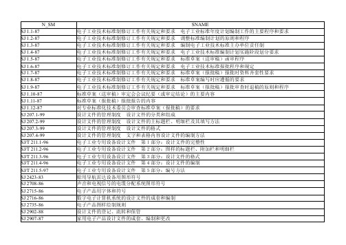
基本环境试验规程 第2部分:各种试验 试验Kd导则:接触点和连接件的硫化氢试验导则 基本环境试验规程 第2部分:各种试验 试验Kc:接触点与连接件的二氧化硫试验导则 基本环境试验规程 第2部分:各种试验 锡焊试验导则 基本环境试验规程 第2部分:各种试验 用IEC68标准中的各项试验模拟贮存影响的导则 基本环境试验规程第2部分:在冲击、碰撞、振动和稳态加速度等动态试验中元件、设备和其它产品的安装和导则 基本环境试验规程 第2部分:各种试验 试验Z/AFc和Z/BFc:温度(寒冷和干热)和正弦振动综合试 基本环境试验规程 第2部分:各种试验 太阳辐射试验导则 基本环境试验规程 第3部分:背景材料 第1节:寒冷(低温)和干热(高温) 基本环境试验规程 第3部分:背景材料 第2节:温度/低气压综合试验 大气腐蚀加速试验问题的评价 半导体器件 机械和气候试验方法 工业过程测量与控制设备的工作条件 第一部分:温度、湿度、大气压力 工业过程测量与控制设备的工作条件 第三部分:机械影响因素 工作系统设计中的人类工效学原则 音频电力负荷控制系统 环境试验方法 汽车收放机环境试验要求和试验方法 通用型应用电视设备环境要求及试验方法 半导体集成电路机械和气候试验方法 雷达设备可靠性鉴定试验及验收试验 雷达设备研制过程中可靠性监控程序 船用导航雷达可靠性试验方法 黑白电视接收机可靠性鉴定试验及验收试验 载波通信设备可靠性试验方法 传真机可靠性试验方法 卫星通信地球站无线电设备可靠性试验方法 彩色电视广播接收机可靠性管理 彩色电视广播接收机可靠性增长与管理 机载雷达热设计规范 电气绝缘的热评定与分类
SJ/Z 9001.8-87 SJ/Z 9001.9-87 SJ/Z 9001.10-87 SJ/Z 9001.11-87 SJ/Z 9001.12-87 SJ/Z 9001.13-87 SJ/Z 9001.14-87 SJ/Z 9001.15-87 SJ/Z 9001.16-87 SJ/Z 9001.17-87 SJ/Z 9001.18-87 SJ/Z 9001.19-87 SJ/Z 9001.20-87 SJ/Z 9001.21-87 SJ/Z 9001.22-87 SJ/Z 9001.23-87 SJ/Z 9001.24-87 SJ/Z 9001.25-87 SJ/Z 9001.26-87 SJ/Z 9001.27-87 SJ/Z 9001.28-87 SJ/Z 9001.29-87 SJ/Z 9001.30-87 SJ/Z 9001.31-87 SJ/Z 9001.32-87 SJ/Z 9001.33-87 SJ/Z 9001.34-87 SJ/Z 9001.35-87 SJ/Z 9001.36-87
C 福乐斯 绝热材料产品技术性能

福乐斯技术手册C 7
福乐斯技术手册C 8~10
福乐斯技术手册C 11~12-1
“福乐斯”("Armafl ex")以合成橡塑为基材经发泡在材料内部形成无数封闭的空气泡,因空气的导热系数仅为0.026 W/m.k,故“福乐斯”("Armafl ex")是靠闭泡内的空
气而非橡塑材料实现保温隔热。
同时闭泡结构又具有优异的抗水汽渗透能力,形成内
福乐斯技术手册C 12-1~12-2
阿乐斯国际有限公司美国R&D部门研究表明:在一定范围内,“福乐斯”(
导热系数随密度的升高而增大。
福乐斯技术手册C 12-2
为水汽含量百分率,与湿阻因子μ、使用年数
如需详细了解,请咨询我公司技术部门。
例如当环境温度30℃、相对湿度
级“福乐斯”(表面系数9W/m2K)保温时
福乐斯技术手册C 12-2~12-3
其中空气的透湿系数δa i r=0.01988/P(P为当地大气压,标准大气压
δ=1.962X10⁻¹⁰kg/m.s.Pa),以空气的湿阻因子μ=1、一级福乐斯的湿阻因子μ≥10,000,则一级福乐斯的透湿系数δ≤1.96X10-14kg/m.s.Pa。
福乐斯技术手册C 12-3~12-4
福乐斯技术手册C 12-5
福乐斯技术手册C 12-5
福乐斯技术手册C 12-6~12-7
温度一定时,表面放热系数
低,保冷层厚度δ越薄。
防凝露厚度(如25mm)比玻璃棉的常用厚度(如50mm)要薄三分之一以上,其表面系数高是又一主要原因。
福乐斯技术手册C 12-8~12-12。
ELCOMETER 319 便携式露点仪中文说明书

--------标准型和高级型操作手册
目录
1. 简介......................................................................................................................................................................................................................... 2 2. 快速启动................................................................................................................................................................................................................. 6 3. 启动......................................................................................................................................................................................................................... 7 4. 读数记录............................................................................................................................................................................................................... 13 5. 分批记录数据(高级型)................................................................................................................................................................................... 16 6. 7. 8. 统计................................................................................................................................................................................................................. 19 限值................................................................................................................................................................................................................. 22 菜单................................................................................................................................................................................................................. 23
- 1、下载文档前请自行甄别文档内容的完整性,平台不提供额外的编辑、内容补充、找答案等附加服务。
- 2、"仅部分预览"的文档,不可在线预览部分如存在完整性等问题,可反馈申请退款(可完整预览的文档不适用该条件!)。
- 3、如文档侵犯您的权益,请联系客服反馈,我们会尽快为您处理(人工客服工作时间:9:00-18:30)。
2SJ319(L), 2SJ319(S)
Silicon P Channel MOS FET
REJ03G0858-0200
(Previous: ADE-208-1192)
Rev.2.00
Sep 07, 2005 Description
High speed power switching
Features
• Low on-resistance
• High speed switching
• Low drive current
• No secondary breakdown
• Suitable for switching regulator, DC-DC converter
Outline
Absolute Maximum Ratings
(Ta = 25°C)
Item Symbol Value Unit
Drain to source voltage V DSS –200 V Gate to source voltage V GSS ±20 V Drain current
I D –3 A Drain peak current
I D (pulse) Note 1
–12 A
Body to drain diode reverse drain current I DR –3 A Channel dissipation Pch Note 2 20 W
Channel temperature
Tch 150 °C Storage temperature Tstg
–55 to +150
°C
Notes: 1. PW ≤ 10 µs, duty cycle ≤ 1% 2. Value at Tc = 25°C
Electrical Characteristics
(Ta = 25°C)
Item
Symbol Min Typ Max Unit Test Conditions Drain to source breakdown voltage V (BR) DSS –200 — — V I D = –10 mA, V GS = 0 Gate to source breakdown voltage V (BR) GSS ±20 — — V I G = ±100 µA, V DS = 0 Gate to source leak current I GSS — — ±10 µA V GS = ±16 V, V DS = 0 Zero gate voltage drain current I DSS — — –100 µA V DS = –160 V, V GS = 0 Gate to source cutoff voltage
V GS (off) –2.0 — –4.0 V I D = –1 mA, V DS = –10 V Static drain to source on state resistance R DS (on) — 1.7 2.3 Ω I D = –2 A, V GS = –10 V Note 3
Forward transfer admittance |y fs | 1.0 1.7 — S I D = –2 A, V DS = –10 V Note 3
Input capacitance Ciss — 330 — pF Output capacitance Coss — 130 — pF
Reverse transfer capacitance Crss — 25 — pF V DS = –10 V
V GS = 0 f = 1 MHz Turn-on delay time t d (on) — 10 — ns
Rise time
t r — 30 — ns
Turn-off delay time
t d (off) — 40 — ns
Fall time
t f — 30 — ns
I D = –2 A V GS = –10 V R L = 15 Ω Body to drain diode forward voltage V DF — –1.15 — V I F = –3 A, V GS = 0 Body to drain diode reverse recovery time t rr
— 180 — ns I F = –3 A, V GS = 0
di F /dt = 50 A/µs
Note: 3. Pulse test
Main Characteristics
Package Dimensions
Ordering Information
Part Name
Quantity
Shipping Container
2SJ319L-E 3200 pcs Box (Sack) 2SJ319STL-E 3000 pcs
Taping
Note: For some grades, production may be terminated. Please contact the Renesas sales office to check the state of
production before ordering the product.
RENESAS SALES OFFICES
Refer to "/en/network" for the latest and detailed information.
Renesas Technology America, Inc.
450 Holger Way, San Jose, CA 95134-1368, U.S.A
Tel: <1> (408) 382-7500, Fax: <1> (408) 382-7501
Renesas Technology Europe Limited
Dukes Meadow, Millboard Road, Bourne End, Buckinghamshire, SL8 5FH, U.K.
Tel: <44> (1628) 585-100, Fax: <44> (1628) 585-900
Renesas Technology Hong Kong Ltd.
7th Floor, North Tower, World Finance Centre, Harbour City, 1 Canton Road, Tsimshatsui, Kowloon, Hong Kong
Tel: <852> 2265-6688, Fax: <852> 2730-6071
Renesas Technology Taiwan Co., Ltd.
10th Floor, No.99, Fushing North Road, Taipei, Taiwan
Tel: <886> (2) 2715-2888, Fax: <886> (2) 2713-2999
Renesas Technology (Shanghai) Co., Ltd.
Unit2607 Ruijing Building, No.205 Maoming Road (S), Shanghai 200020, China
Tel: <86> (21) 6472-1001, Fax: <86> (21) 6415-2952
Renesas Technology Singapore Pte. Ltd.
1 Harbour Front Avenue, #06-10, Keppel Bay Tower, Singapore 098632
Tel: <65> 6213-0200, Fax: <65> 6278-8001
Renesas Technology Korea Co., Ltd.
Kukje Center Bldg. 18th Fl., 191, 2-ka, Hangang-ro, Yongsan-ku, Seoul 140-702, Korea
Tel: <82> 2-796-3115, Fax: <82> 2-796-2145
Renesas Technology Malaysia Sdn. Bhd.
Unit 906, Block B, Menara Amcorp, Amcorp Trade Centre, No.18, Jalan Persiaran Barat, 46050 Petaling Jaya, Selangor Darul Ehsan, Malaysia
Tel: <603> 7955-9390, Fax: <603> 7955-9510。