EOC1650_UsersManual_20090109_V1.0
1650简明中文操作手册

Siemens ADVIA 1650 简明中文操作手册西门子医疗诊断设备有限公司一操作流程表……………………………………………………………l-3 二开机……………………………………………………………………1-4 三定标和质控……………………………………………………………1-6 四样本分析………………………………………………………………1-8 五关机……………………………………………………………………1-10 六维护保养………………………………………………………………l-11【下面的流程图指示了常规操作流程】[开机]【定标和质控】[样本分析][关机][维护保养]1.先开电脑主机,显示器、打印机,启动Windows NT操作系统。
2.然后打开水机开关,检查仪器台面是否有障碍物影响针和搅拌棒的移动,避免开机后造成对仪器的损伤。
打开生化仪主机开关,将【Operate/Standby】开关拨至【OPERATE】。
3.当计算机屏幕显示至【Startup】窗口时,选择【New Start】并输入用户密码“Siemens”(bayer)?,然后点击【OK】。
如果选择【Re-start】系统将保留原来的数据。
4.在Operation Panel菜单下,按【INITIALIZE】键执行初始化,使仪器进入【READY】状态。
注:在按【INITIALIZE】键之前请务必确认试剂盘盖已经盖好,以防撞针!5.检查下列组件是否正常或清洁:试剂针及样品针反应盘冲洗站搅拌棒针清洗杯和缓冲液桶稀释盘冲洗站反应杯盖6.点击【Main.】→【System Monitor】,检查系统状态是否正常。
正常状态为:a) Thermo.circ.vol显示流量为2000~6000之间;b) 其余的状态显示均为OK。
7.检查试剂:检查内容包括:系统试剂、化学试剂、清洗液。
a) 打开仪器中间的前门,检查孵育槽油剂、稀释液、Detergent、Conditioner以及离子缓冲液的量是否足够。
tm1650驱动程序案例
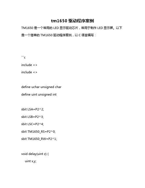
tm1650驱动程序案例TM1650是一个常用的LED显示驱动芯片,常用于制作LED显示屏。
以下是一个简单的TM1650驱动程序案例,以C语言编写:```cinclude <>include <>define uchar unsigned chardefine uint unsigned intsbit LSA=P2^2;sbit LSB=P2^3;sbit LSC=P2^4;sbit TM1650_RS=P2^0;sbit TM1650_RW=P2^1;void delay(uint z) {uint x,y;for(x=z;x>0;x--)for(y=110;y>0;y--);}void Write_Com(uchar com) {LSA=0;LSB=0;LSC=0;P0=com; //先写地址,后写数据delay(5);LSB=1; //将LSB置1,再改变LSA即可写入数据 delay(5);LSA=1; //先写地址,后写数据delay(5);LSC=1; //先写地址,后写数据}void Write_Data(uchar date) {P0=date; //向指定的地址写入数据delay(5);}void InitTM1650() { //初始化TM1650芯片Write_Com(0x38); //设置基本模式Write_Com(0x0C); //设置段选位反转Write_Com(0x06); //开显示,光标位移到右端 Write_Com(0x01); //清除显示,光标移到最左边}void main() { //主函数InitTM1650(); //初始化TM1650芯片while(1) { //循环显示数字Write_Com(0x80); //设置段选位为第一段Write_Data('1'); //向第一段写入数字'1'delay(50); //延时一段时间Write_Com(0x9F); //设置段选位为第五段Write_Data('2'); //向第五段写入数字'2'delay(50); //延时一段时间Write_Com(0xDF); //设置段选位为第七段Write_Data('3'); //向第七段写入数字'3'delay(50); //延时一段时间}}```。
边缘计算机 EC900 系列 用户手册说明书

边缘计算机EC900 系列用户手册(适用于 Debian10)Version1.3,2023 年 5月本手册中描述的软件是根据许可协议提供的,只能按照该协议的条款使用。
版权声明© 2023 映翰通网络保留所有权利。
商标InHand 标志是映翰通网络的注册商标。
本手册中的所有其他商标或注册商标属于其各自的制造商。
免责声明本公司保留对此手册更改的权利,产品后续相关变更时,恕不另行通知。
对于任何因安装、使用不当而导致的直接、间接、有意或无意的损坏及隐患概不负责。
目录1 导言 (1)2 硬件安装说明 (1)2.1介绍 (1)2.2 EC900面板 (2)2.3 EC900外部连接器 (3)2.3.1 以太网 (3)2.3.2 串口 (3)2.3.3 CAN (4)2.3.4 开关量输入接口(Digital Input) (5)2.3.5 开关量输出接口(Digital Output) (5)2.3.6 USB (6)2.3.7 LED (6)2.3.8 用户可编程按键 (9)2.3.9 直流输入 (9)2.3.10 SIM卡插槽 (10)2.3.11 MicroSD卡槽 (10)2.3.12 恢复出厂按键 (11)2.3.13 开关机按键 (11)2.3.14 天线接口 (12)2.3.15 拨码开关 (13)2.3.15 mSATA硬盘接口 (13)3 入门 (14)3.1连接到EC900 (15)通过SSH Console进行连接 (16)3.2用户账户管理 (18)切换到root用户 (18)创建和删除用户账户 (19)禁用默认的用户账户 (19)3.3网络设置 (20)配置以太网口 (20)设置一个静态IP地址 (20)设置一个动态IP地址 (20)3.4系统管理 (21)查询固件版本 (21)查看可用磁盘空间 (21)调整时间 (22)设置时区 (23)使用localtime文件 (24)关闭设备 (25)启动设备 (25)4 外设接口的高级配置 (25)4.1串口 (26)更改串口设置 (26)查看串口信息: (29)设置COM1串口的波特率: (29)设置COM2串口的波特率 (30)4.2 USB接口 (30)USB自动挂载 (30)micro SD卡自动挂载 (30)4.3 CAN总线接口 (33)配置连接CAN接口 (34)4.4 IO调试 (34)5 无线网络连接配置 (35)5.1 配置蜂窝网络 (35)使用nvram (35)5.2 GPS (39)5.3 配置Wi-Fi连接 (40)Wi-Fi的其他功能 (42)6 安全 (44)sudo机制 (45)防火墙 (45)7 系统恢复出厂设置及更新 (45)恢复出厂设置 (46)系统升级 (46)1 导言本用户手册适用于基于Arm架构的边缘计算机EC900,并涵盖整套适用于所有支持型号的说明。
tm1650中文资料_数据手册_参数

©Titan Micro Electronics
V1.0
1
管脚信息
LED 驱动控制/键盘扫描专用集成电路 TM1650
管脚功能
端口 名称 DIG1 DIG2 DIG3 DIG4 SCL SDA A/KI1 B/KI2 C/KI3 D/KI4 E/KI5 F/KI6 G/KI7 DP/KP GND VDD
功能特点
两种显示模式:8段×4位和7段×4位 段驱动电流大于25mA,位驱动电流大于150mA 提供8级亮度控制 键盘扫描:7×4bit内部集成三极管驱动 高速两线式串行接口 内置时钟振荡电路 内置上电复位电路 支持2.8V-5.5V电源电压 提供DIP16及SOP16封装
适用领域: 家用电器产品如机顶盒、空调、DVD/VCD等显示的驱动。
VIL
低电平输入电压
2.8
VIH
高电平输入电压
2.8
VOH
高电平输出电压
VDD-0.4
VDD
VOL
低电平输出电压
0.3
VOLdig VOLdig VOHdig VOLki VOLki
IDN1 VR
DIG 引脚低电平输出电压 DIG 引脚低电平输出电压 DIG 引脚高电平输出电压 KI 引脚低电平输出电压 KI 引脚低电平输出电压 KI 引脚输入下拉电流 上电复位的默认电压门限
键盘扫描码:
TM1650 对应键盘扫描码:
编址
DIG4
DIG3
DIG2
A/KI1
47H
46H
45H
B/KI2
4FH
4EH
4DH
C/KI3
57H
56H
55H
D/KI4
infinite 双网控制主机安装编程手册

Infinite 主机安装编程手册 - 版本 Version 3.00本产品通过了CE和CCC认证.。
华际电子及EL3000公司声明:此产品符合CE和中国CCC认证机构相关规定。
如果内容数据改变恕不另行通知。
目录目录 (2)第一章系统简介 (5)1.1: 文档协定 (5)1.2: 特性 (6)1.3: 系统概述 (7)1.4: 系统布置 (9)第二章: 安装指导 (13)2.1: 准备安装 (13)2.2: 打开外壳 (14)2.3: 固定主机 (14)2.4: 后背方拆开关 (15)第三章 系统基本操作 (16)3.1: Infinite-LCD版系统管理主机操作 (16)3.2: 系统状态显示 (16)3.3: 字母数字键盘 (17)3.4: LCD液晶显示器显示 (17)3.5: 布防/撤防(Arming/Disarming) (18)3.6: 通过短信息遥控布撤防 (20)3.7:前面板紧急报警 (21)第四章:高级系统操作 (22)4.1: 菜单导航 (22)4.2: 停止通讯(STOP COMM.:菜单1) (22)4.3: 防区的旁路/旁路恢复(Sensor Bypass:菜单2) (23)4.4: 用户密码(USER CODES:菜单4) (23)4.5:修改Follow Me电话号码(Follow Me:菜单5) (25)4.6: 事件记录(EVENT LOG:菜单6) (25)4.7: 服务菜单(SERVICE:菜单7) (26)第五章: 双向语音对讲监听 (30)5.1: 主动拨入通讯 (30)5.2: 报警拨出通讯 (31)第六章: 家电自动化 (33)6.1: 用键盘控制电器 (33)6.2: 用无线四键按钮控制电器 (33)6.3: SMS 短信息控制 (33)6.4: 自动定时控制电器 (34)第七章: 设备 (36)7.1: 无线设备注册(Device Registration) (36)7.2: 设备描述名称(Device Descriptors) (36)7.3: 删除设备(Device Deletion) (36)7.4: 监控时间(Supervision Time:菜单[916]) (37)7.5: 再同步(Re-Synchronization:菜单[917]) (37)7.6: 防区(Zones:菜单[911]) (37)7.7: 遥控按钮(Keyfobs :菜单[912]) (40)7.8: 键盘(Keypads:菜单[913]) (41)7.9: 无线信号中继器(Repeaters:菜单[914]) (43)7.10: 无线警号(Exteral Siren) (43)7.11: 智能钥匙(Smartkeys:菜单[913],将来预留功能) (44)第八章:进入/退出延时及布防提示音 (45)8.1: 布/撤防延时(Entry/Exit:菜单[92]) (45)8.2: 退出布防(Arm on Exit:菜单[923]) (45)8.3: 布防语音提示方式(Arming Tones:菜单[93]) (45)8.5: 选择提示音输出设备(Tones Output:菜单[938]) (47)第九章: 系统选项 (48)9.1: 报警次数限制设置(SWINGER:菜单[9401]) (48)9.2: 错误用户密码锁键盘设置(Code Lockout:菜单[9402]) (48)9.3: 是否容许强制布防(Forced Arm:菜单[9403]) (48)9.4: 是否容许家居自动化控制(HA CONTROL:菜单[9404]) (48)9.5: 紧急求救报警是否有声(Panic Alarm:菜单[9405]) (48)9.6: 一键布防(One-Key Arming:菜单[9406]) (49)9.7: 辅助的进入延时(SUPP ENT DELAY:菜单[9407]) (49)9.8: 进入偏离(ENT DEVIATION:菜单[9408]) (49)9.9: 交流断电延时报警时间(AC LOSS DELAY:菜单[9409]) (49)9.10: 布防状态显示(Arm Status :菜单[9410]) (50)9.11: 显示系统标识(Banner :菜单[9411]) (50)9.12: 可编程输出(PGM Output:菜单[9412]) (50)9.13: Guard Code (将来使用) (51)9.14: 时间/日期格式 (Time/Date Format) (51)9.15: 无布防操作提示 (“No Arm” Indication) (52)9.16: 监控布防 (Supervised Arm) (52)第十章:通讯 (53)10.1: 通讯账户(A c c o u n t s 菜单[951]) (53)10.2: 通用账户选项(General Account Options) (55)10.3: 遥控编程(Remote Programming) (56)10.4: 服务电话(Service Call) (58)10.5: 短信息中心(SMS Center菜单[954]) (58)10.6: 通讯选项( Communications Options菜单[9551]) (58)10.7: 双向监听对讲功能设置(Two-Way Audio Options) (60)10.8: GSM接收信号强度报道(GSM RX Report) (61)10.9:事件传输选项( Event Options) (61)第十一章:家具自动化控制编程 (64)11.1: X10 概述(X10 Overview) (64)11.2: 家居自动化控制单元( HA Units) (64)11.3: 房屋根码(House Code) (66)11.4: 短信息确认(SMS Confirmation) (66)第十二章:系统初始化 (68)12.1: 初始化( Initialization) (68)12.2: 缺省编程恢复(Default Program Restore) (68)12.3: 清除用户密码(Clear User Codes) (68)12.4: 清除无线发射器(Clear Wireless Transmitters) (68)12.5: 检测模块(Find Modules) (68)附录A:菜单结构 (70)附录B:Infinite事件代码总表 (75)附录C:报警监听功能 (77)附录D:Infinite-LCD无线系统安装注意 (78)附录E:Infinite无线系列发射设备中文说明 (80)1、EL-2600/EL-2600PI/EL-2645/ EL-2645 PI无线红外探测器 (80)2.EL-2650无线方向幕帘探测器 (83)3、EL-2601无线门磁 (85)4、EL-2614/2611无线按钮 (87)5、烟感探测器 (EL-2603) (88)6、无线键盘 (EL-2620/EL-2640) (88)发射器基本参数 (90)第一章系统简介此说明书为安装和编程操作Infinite主机而设计,我们强烈建议您在安装和调试此设备之前全面地阅读此手册,这样才能更好的理解和利用主机功能,我们鼓励最终用户阅读使用手册,如果有问题请致电供货商和工程商。
TrueSecure TM GTU Series Fingerprint Module User M

TrueSecure TMGTU Series Fingerprint ModuleUser Manual���� 10� �01�Revision: V1.00 Date: ���� 10� �01�Table of ContentsTable of Contents1 Introduction .............................................................................................................32 Functional Description . (3)View Image (5)Enro�� (6)Verif� (7)Identif� (8)Se�ect User (9)De�ete User ..........................................................................................................................10Save Image ..........................................................................................................................10View Log (10)Settings (11)Simi�arit� Thresho�d .............................................................................................................11Exit (11)Introduction1 IntroductionThis demonstration program is a simple but helpful program that will assist users to becomefamiliar with the features of the GTU series of fingerprint modules. The program allows easyimplementat of all the major functions required for fingerprint recognition.2 Functional DescriptionAfter program installation, execute the program by double-clicking on the Gingy_Demo.exe in theSDK program directory. After execution the following start up screen will be displayed.The program includes the following fingerprint recognition functions:Functional DescriptionThis start up screen contains a set of fingerprint module functions which are described in thefollowing section.Functional Description View ImageThe View Image can be selected to view the recorded fingerprint image. This function is used toadjust the image quality for the CMOS optical device. As the default settings may be not suitablefor certain environment or finger types, the user can adjust the brightness, contrast and gamma toget a satisfactory image quality for later enrollment or authentication.Functional DescriptionEnrollThe Enroll function is used to enroll a new fingerprint as the current user. At least three fingerprints are required to complete the enrollment. Place the finger on the reader for at least three times until the enrolled quality is displayed.The fingerprint reader will take the common features of these fingerprints and after a few seconds of processing, the reader will inform the user of the enrolment result.The following table shows the five levels of quality that are provided.You can Select Enroll to enter the enrollment mode. The screen is the same as the snap function. After enrolling a fingerprint successfully, a dialog box will appear which shows the enrolled quality. The user is now requested to input a name and choose the enrolled finger. After inputtingthe desired data, select “Save” to save the data.Functional Description VerifyThe Verify function is used to check a live-scanned fingerprint from the current user. It implementsonly a one-to-one matching. The matching compares a live-scanned fingerprint image against apreviously enrolled fingerprint image, to verify that they came from the same finger. To use thisfunction place a finger on the reader and the fingerprint reader will check it out automaticallyaccording to the security level settings.The objects to be compared are the live-scanned fingerprint image and the final fingerprinttemplate - EnrlTemplate, which is the data that was saved during enrollment. After a successfulsnapping, the live-scan fingerprint image data is stored in the main memory. The EnrlTemplate canbe chosen by clicking Select User or by creating a new user through the enrollment process.The Verify function can be selected to enter the matching fingerprint mode. Before clicking theVerify button, a user must first be selected, otherwise the following screen will appear.After verification, the result will be displayed on the screen to show if the verification achieved amatch or if it failed. See Identify for details.Functional DescriptionIdentifyThe Identify function is used to identify a live-scanned fingerprint image from the database. This function implements a one-to-many matching. The matching process compares a live-scanned fingerprint image with a previously enrolled database. To use this, a finger should be placed upon the reader to allow the fingerprint reader to check it out automatically according to the security level settings.The Identify function can be selected to enter the matching fingerprint mode. After identification, the result will be displayed on the screen to show if the identification has achieved a match or if ithas failed. If the identification is successful the user information will also be shown on the screen.Functional Description Select UserThe Select User function is used to select a User for verification. The user data files are createdafter enrollment. Once a user has been selected, it will become the target for verification. The nameof the user will be displayed on the demo program screen.There are two methods to change the target that is to be verified:▆Select another user from the function of Select User.▆After enrollment, the enrolled user will become the new matching target automatically.The Select User can be selected to enter the Select User mode. The following screen will appearshowing the user list, containing the name, enrolled finger and enrolled class. To select a user,choose the user and click the “OK” button or double-click on the desired user.Functional Description Delete UserThe Delete User function will delete a User from the database. Once you have selected a user, the user will be deleted from the list.Save ImageThe Save Image function is used to save the fingerprint image to a file. After a successful fingerprint snap operation, the fingerprint image will be stored in the main memory. A fingerprint image can be saved using this function. Select the Save Image function to enter the Save Image mode. Select a specified folder and input the filename.According to the user’s requirements, there are two file types that can be selected:▆File TypeBMP: Save the fingerprint image in bitmap file format.View LogThe View Log is used to view the operation history. The log can be sorted by “Date”, “Name” or“Action” by clicking the relative radio buttons. See the dialog box below.Functional DescriptionSettingsSecurity LevelThe default security level is Medium. Set up the security level for matching by setting the verification threshold. High is the safest mode, providing a FAR of less than 1/100,000. Fair is a less tight mode, providing a FAR of less than 1/1000.DeviceSelect a device for the system.Enroll ModeSelect an enrolled mode for the enrollment. All three modes will give high matching performances. However, larger template sizes will require the storage of more fingerprint data, giving higher accuracy but lower speed. The user may use the different modes depending upon their applications.For smaller capture device areas or 1-1 verification or 1-few identifications, the 504-byte mode is recommended. Where it is required to identify a large number of fingerprints, then speed may be the main concern and subsequently the 168-byte or 336-byte mode is recommended.Similarity ThresholdThe Similarity Threshold function is used to adjust the Security Level. The higher the Similarity Threshold, the higher the security levels. However higher security levels will also result in enrollment difficulties.ExitThe Exit function is used to terminate the demo program.Functional DescriptionCopyright© �01� b� HOLTEK SEMICONDUCTOR INC.The information appearing in this Data Sheet is believed to be accurate at the timeof publication. However, Holtek assumes no responsibility arising from the use ofthe specifications described. The applications mentioned herein are used solely forthe purpose of illustration and Holtek makes no warranty or representation that such applications will be suitable without further modification, nor recommends the use ofits products for application that may present a risk to human life due to malfunction or otherwise. Holtek's products are not authorized for use as critical components in lifesupport devices or systems. Holtek reserves the right to alter its products without prior notification. For the most up-to-date information, please visit our web site at http://www.ho�.Note that Holtek’s fingerprint recognition products have been designed in conjunction withGing� T echno�og�.。
Installation Manual

Fast installation for IR Remote Control Code Analyzer 2009 -Professional & YG-920 V8.01. Copy the directory “IRReader2009” to your harddisk, remove all attributes of all files, or run setup.exe.2. If using RS-232, please plug in DC9V ,connect RS-232 port to COM1 or COM2, goto step 4.3. If using USB port, connect USB port to PC ’s usb port, PC will auto install driver for receiver.4. Run “IRReader.EXE”, refer to step 1 to step 5 below.Step 3: set receiver work mode to 38K Carrier.Fast installation for IR Remote Control Code Analyzer 2009 -Professional & YG-920 V6.01.Copy the directory “IRReader2009” to your harddisk, remove all attributes of all files, or run setup.exe.2. If using RS-232, please plug in DC9V,connect RS-232 port to COM1 or COM2, goto step5.3. If using USB port, connect USB port to PC,DC9V isn’t needed, PC report “Found New Hardware”, show below.Select “Continue Anyway”.Select“Next”until complete, maybe you need to restart computer.4. Open Device Manager, Extract “Ports(COM & LPT)”,you can see “Prolific U SB-to-Serial Bridge (COM3)”,that means the Sampler maping to COM3, than run IRReader.exe, select “COM3”,Sampler may map to different serial port in different computer or USB.5. Run “IRReader.EXE”,select sampler and communication port ”COM3”, than pre ss down “ON/OFF” button on top-right ofwindow. Now start to use.Step 3: set receiver work mode to 38K Carrier.。
TM-U950 User's Manual

TM-U950User’s Manual / Bedienungsanleitung Gebruikershandleiding / Manuel d’utilisation Manual do utilizador / Manual del usuarioManuale dell’utente401406102Printer PartsDIP Switch Tables34Serial interfaceSW FunctionON OFF 1-1Data word length 7 bits 8 bits 1-2ParityEnabled Disabled 1-3Parity selectionEvenOdd1-4 ~ 1-5Transmission speed (see table below)1-6Display module connection ConnectedNotconnected 1-7Data receive error IgnoredPrints “?”1-8HandshakingXON/XOFFDTR/DSRTransmission speedSpeed 1-41-51200ON ON 2400OFF ON 4800ON OFF 9600OFF OFFSW Function ON OFF 2-1Auto line feed Always enabled Always disabled 2-2Receive buffer32 bytes2048 bytes2-3Font selection (default)9 × 97 × 92-4Carriage speed default Low High 2-5Handshaking (BUSY)Receive buffer full Offline or receive buffer full 2-6Internal use Fixed —2-7I/F pin 6 reset Enabled Disabled 2-8I/F pin 25 resetEnabledDisabledParallel interfaceSWFunctionON OFF 1-1 ~ 1-5Undefined ——1-6Internal use—Fixed 1-7 ~ 1-8Undefined ——SW Function ON OFF 2-1Auto line feed Always enabled Always disabled 2-2Receive buffer32 bytes2048 bytes2-3Font selection (default)9 × 97 × 92-4Carriage speed default Low High 2-5Handshaking (BUSY)Receive buffer full Offline or receive buffer full 2-6Internal use Fixed —2-7Undefined ——2-8Internal useFixed—All rights reserved. No part of this publication may be reproduced, stored in a retrieval system, or transmitted in any form or by any means, electronic, mechanical, photocopying, recording, or otherwise, without the prior written permission of Seiko Epson Corporation. No patent liability is assumed with respect to the use of the information contained herein. While every precaution has been taken in the preparation of this book, Seiko Epson Corporation assumes no responsibility for errors or omissions. Neither is any liability assumed for damages resulting from the use of the information contained herein.Neither Seiko Epson Corporation nor its affiliates shall be liable to the purchaser of this product or third parties for damages, losses, costs, or expenses incurred by purchaser or third parties as a result of: accident, misuse, or abuse of this product or unauthorized modifications, repairs, or alterations to this product, or (excluding the U.S.) failure to strictly comply with Seiko Epson Corporation’s operating and maintenance instructions.Seiko Epson Corporation shall not be liable against any damages or problems arising from the use of any options or any consumable products other than those designated as Original Epson Products or Epson Approved Products by Seiko Epson Corporation.EPSON and ESC/POS are registered trademarks of Seiko Epson Corporation in the U.S. and other countries. NOTICE: The contents of this manual are subject to change without notice.Copyright © 1995, 1998, 2001 by Seiko Epson Corporation, Nagano, Japan.EMC and Safety Standards AppliedProduct Name: TM-U950/U950PModel Name: M62UA/M114AThe following standards are applied only to the printers that are so labeled. (EMC is tested using the Epson power supplies.)Europe:CE markingSafety:EN 60950North America:EMI:FCC/ICES-003 Class ASafety:UL 1950/CSA C22.2 No. 950 Japan:EMC:VCCI Class AOceania: EMC:AS/NZS3548WARNINGThe connection of a non-shielded printer interface cable to this printer will invalidate the EMC standards of this device. You are cautioned that changes or modifications not expressly approved by SEIKO EPSON Corporation could void your authority to operate the equipment. CE MarkingThe printer conforms to the following Directives and Norms:Directive 89/336/EEC EN 55022 Class BEN 55024IEC 61000-4-2IEC 61000-4-3IEC 61000-4-4IEC 61000-4-5IEC 61000-4-6IEC 61000-4-8IEC 61000-4-11 Directive 90/384/EEC EN 45501FCC Compliance Statement For American UsersThis equipment has been tested and found to comply with the limits for a Class A digital device, pursuant to Part 15 of the FCC Rules. These limits are designed to provide reasonable protection against harmful interference when the equipment is operated in a commercial environment.This equipment generates, uses, and can radiate radio frequency energy and, if not installed and used in accordance with the instruction manual, may cause harmful interference to radio communications. Operation of this equipment in a residential area is likely to cause harmful interference, in which case the user will be required to correct the interference at his own expense.For Canadian UsersThis Class A digital apparatus complies with Canadian ICES-003.Safety PrecautionsThis section presents important information intended to ensuresafe and effective use of this product. Please read this sectioncarefully and store it in an accessible location.TM-U950 User’s Manual 12 TM-U950 User’s ManualWARNING:Shut down your equipment immediately if it produces smoke, a strange odor, or unusual noise. Continued use may lead to fire. Immediately unplug the equipment and contact your dealer or a SEIKO EPSON service center for advice.Never attempt to repair this product yourself. Improper repair work can be dangerous.Never disassemble or modify this product. Tampering with this product may result in injury or fire.Be sure to use the specified power source. Connection to an improper power source may cause fire.Do not allow foreign matter to fall into the equipment. Penetration by foreign objects may lead to fire.If water or other liquid spills into this equipment, unplug the power cord immediately, and then contact your dealer or a SEIKO EPSON service center for advice. Continued usage may lead to fire.CAUTION:Do not connect cables in ways other than those mentioned in this manual. Different connections may cause equipment damage and burning.Be sure to set this equipment on a firm, stable, horizontal surface. The product may break or cause injury if it falls.Do not use in locations subject to high humidity or dust levels. Excessive humidity and dust may cause equipment damage or fire.Do not place heavy objects on top of this product. Never stand or lean on this product. Equipment may fall or collapse, causing breakage and possible injury.To ensure safety, unplug this product before leaving it unused for an extended period.Do not use aerosol sprayers containing flammable gas inside or around this product. Doing so may cause fire.Caution LabelsWARNING:Do not connect a telephone line to the drawer kick-out connector or the display module connector; otherwise, the printer and the telephone line may be damaged.CAUTION:The print head is hot.UnpackingThe following items are included with the standard specification printer. If any item is damaged, contact your dealer.❏Printer❏Paper rolls (2)❏Ribbon cassette❏Power switch cover❏Take-up spool❏Caution label❏Hexagonal lock screws (2) (only for the serial interface) Downloading Drivers, Utilities, and ManualsDrivers, utilities, and manuals can be downloaded from one of the following URLs.For customers in North America, go to the following web site:/ and follow the on-screeninstructions.For customers in other countries, go to the following web site:/Select the product name from the ‘Select any product‘ pulldownmenu.Control PanelRECEIPT FEED buttonPress to feed receipt paper; hold down to feed continuously. JOURNAL/SLIP FEED buttonIn roll paper mode, feeds the journal roll. In slip mode (when the SLIP LED is on or flashing and slip paper is inserted), feeds slippaper.POWER LEDOn when the printer is on.ERROR LEDIndicates an error.RECEIPT OUT LEDIndicates a receipt paper near end or out.TM-U950 User’s Manual 34 TM-U950 User’s ManualJOURNAL OUT LEDIndicates a journal roll paper near end or out.SLIP LEDIndicates slip mode. Flashes while waiting for a slip to be inserted or removed.Removing the Transportation DamperThe printer is protected duringshipping by a transportation damper that you must remove before turning on the printer.Pull the damper out, as shown in illustration 1.Note:Before shipping the printer, reinstall the transportation damper.Using the Power Switch CoverWARNING:If an accident occurs with the power switch cover attached, unplug the power cord immediately. Continued use may cause fire.The enclosed power switch cover ensures that the power switch is not pressed accidentally. To use this cover, install it as shown in illustration 2.Installing the Paper RollsNote:Use only paper rolls that meet the specifications.TM-U950 User’s Manual 51.Make sure the leading edge ofthe paper is straight.2.Turn on the printer and openthe printer cover.3.Insert paper rolls on both thereceipt and journal sides of the printer, as shown inillustration 3. (The journal roll is on the right in this illustration.)4.For each roll, insert the tip of thepaper into the paper inlet and push it in until it is automatically detected and fed into the printer. See illustration 4.5.Tear off the receipt paper on thecutter. If the paper was not fed far enough, press the RECEIPT FEED button to feed additional paper.6.Insert the tip of the journal paperinto the groove in the take-up spool and rotate the spool two or three times to secure the paper. See illustration 5. If not enough paperwas fed, press JOURNAL/SLIP FEEDto feed more.7.Install the take-up spool and close theprinter cover.8.To remove the journal paper roll, firstThen remove the take-up spool. See illustration 6.9.next press the release lever (marked PRESS ) on the appropriate side of the the roll.Inserting Slip PaperNotes:Do not use wrinkled, folded, or curled paper.Use only slip paper that matches the printer’s specifications.To prevent paper jams, install both paper rolls in the printer even if you plan to print only on slip paper.1.When the SLIP LED flashes,guide. See illustration 7.2.in and begins printing.CAUTION:Be sure to put the caution label exactly in the position shown. If you put it another place, such as over the slip paper inlet, the printer may bedamaged.Installing a RibbonUse the EPSON ERC-31. The use of any ribbon cassettes other than those approved by EPSON may damage the printer and will void the warranty.1.Turn the printer on and open the ribbon cover.2.take up any slack.3.ribbon in the correct position.4.the print head without wrinkles or creases.5.To remove the ribbon cassette, grasp the ribbon cassette’s taband pull it out of the printer.Using the MICR Reader (Option)The optional, factory-installed magnetic ink character recognition (MICR) reader lets the printer read MICR ink on personal checks.6 TM-U950 User’s ManualTM-U950 User’s Manual 7CAUTION:To prevent paper jams, be sure both paper rolls are installed.Do not insert checks with staples in them; do not insert wrinkled checks.1.The SLIP light flashes.2.Insert the check face down, with theMICR characters on the right-hand side.3.Insert the check straight into the inlet,using the right edge of the inlet as a guide, as far as the check will go. See illustration 9.4.The printer starts drawing the checkin. Let go of the check immediately. The SLIP LED goes from blinking to on.5.When MICR reading is complete, the printer ejects the checkand the SLIP LED starts blinking again.6.Remove the check by pulling it straight out (not at an angle).The SLIP LED goes off.Cleaning the Optional MICR MechanismClean the MICR head and MICR roller every 6000 passes or once a month. Note:If you encounter frequent MICR reading errors, use the procedure below.For the MICR headUse a moistened cleaning sheet, such as PRESAT brand (KIC) “Check Reader Cleaning Card” or an equivalent commercially available cleaning sheet. For the MICR feed rollerUse an adhesive cleaning sheet available from EPSON. Contact your dealer.Cleaning procedureUse this procedure for both cleaning sheets.1.Load both paper rolls into the printer; then turn off the power.2.Open the front cover and turn the power back on while holdingdown the JOURNAL/SLIPbutton.8 TM-U950 User’s Manual3.Press the JOURNAL/SLIP button 3 times.4.Close the front cover (the SLIP LED flashes).5.Follow the instructions on the cleaning sheet. You will insertthe cleaning sheet the same way you insert a normal check.6.When the sheet is ejected, remove it from the printer; then turnoff the power.TroubleshootingLEDs on the control panel do not come onCheck the power cable and power outlet. If the outlet is controlled by a switch or timer, use another outlet.ERROR LED is on (not flashing) with no printingIf RECEIPT OUT or JOURNAL OUT is on , a paper roll is not installed or nearly out. If these LEDs are off , the cover is not closed properly.ERROR LED is flashing with no printing (and no paper jam)The print head may be overheated. Printing resumes after the print head cools. If this does not occur, turn the printer off for 10 seconds and then back on. If there is still a problem, contact a qualified servicer.The printer appears to be printing, but nothing is printedCheck ribbon installation and ribbon wear.A line of dots is missingThe print head may be damaged. Stop printing and contact a qualified servicer.Removing Jammed PaperCAUTION:Do not touch the print head because it can be very hot after printing.1.Turn the printer off and open the printer cover.TM-U950 User’s Manual 92.For a journal roll paper jam, cut with scissors or a knife, as shown in illustration 10, and remove the take-up spool.3.Cut the paper from the paper rolls as shown in illustration 11.4.If paper is caught in the automatic cutter, open the cutter blade by turning the gear in the direction shown in illustration 12.5.Move the OPEN ↔ LOCK lever on each side of the printer in the direction shown in illustration 13; the cutter opens automatically.6.Pull the paper out gently. If it tears, remove any pieces.7.If necessary, remove the print head cover. Loosen the screw on the right as shown in illustration 14. (Replace it by sliding the tab in the slot, and fasten the screw.)8.After clearing all paper, close and lock the cutter unit (lock both locks), andreinstall the paper rolls.TM-U950 SpecificationsPrinting method Serial impact dot matrixHead wire configuration9-pin vertical line, wire pitch 0.353 mm {1/72"}, 0.29 mm {0.01"} wirediameterPrinting direction Bidirectional, minimum distance printingPrinting width Roll paper: 61.1 mm {2.41"}; slip paper: 135.6 mm {5.34"}Characters per line (default)9 × 9: roll paper = 30; slip paper = 66 7 × 9: roll paper = 40; slip paper = 88Character spacing(default)9 × 9: 3 dots (half dots); 7 × 9: 2 dots (half dots)Print speed High-speed —9 × 9: 233 characters/second7 × 9: 311 characters/secondLow-speed —9 × 9: 200 characters/second7 × 9: 267 characters/secondPaper feed speed Approx. 60.3 ms/line (4.23 mm {1/6"} feed);Approx. 86.36 mm/second {3.4"/second} continuous feed Line spacing (default) 4.23 mm {1/6"}Number of characters Alphanumeric characters: 95; International characters: 32Extended graphics: 128 × 9 pages (including space pages) Character structure9 × 9 or 7 × 9Paper roll (single-ply)Size:Width: 69.5 ± 0.5 mm {2.74 ± 0.02"}Maximum outside diameter: 83 mm {3.27"}Paper roll spool inside diameter: 10 mm {0.39"} or more Slip paper Normal, carbon-copy, and pressure-sensitiveNumber of copies for slip Original + 4 (at 20 to 40°C {68 to 104°F})Original + 1 to 3 copies (at 5 to 40°C {41 to 104°F})Total slip thickness0.09 to 0.36 mm {0.0035 to 0.0141"}Ribbon cassette ERC-31Buffer size32 bytes or 2KB, depending on the DIP switch settingSupply voltage+24 VDC ± 10%Current consumption (at 24V)Printing receipt and journal paper (40 columns):Mean: Approx. 1.8A (alphanumeric characters)Peak: Approximately 8.0AFeeding slip paper to the print start position or MICR reading: Mean: Approx. 2.3A for approx. 1.4 secondsLife Mechanism:7,500,000 linesPrint head:150 million charactersRibbon:4,500,000 charactersMICR:240,000 passesMTBF180,000 hoursMCBF18,000,000 linesTemperature Operating: 5 to 40°C {41 to 104°F}Storage:–10 to 50°C {14 to 122°F}, except for ribbon Humidity Operating:30 to 80% RHStorage:30 to 90% RHOverall dimensions194.5 × 251 × 298 mm {7.7× 9.9× 11.7"}(H × W × D)Weight (mass)Approximately 5.6 kg {12.3 lb}10 TM-U950 User’s Manual。
- 1、下载文档前请自行甄别文档内容的完整性,平台不提供额外的编辑、内容补充、找答案等附加服务。
- 2、"仅部分预览"的文档,不可在线预览部分如存在完整性等问题,可反馈申请退款(可完整预览的文档不适用该条件!)。
- 3、如文档侵犯您的权益,请联系客服反馈,我们会尽快为您处理(人工客服工作时间:9:00-18:30)。
WirelessAccess Point & Client BridgeUser’s ManualVersion: 1.1Table of Contents1INTRODUCTION (5)1.1F EATURES (5)1.2P ACKAGE C ONTENTS (6)1.3S AFETY G UIDELINES (6)1.4S YSTEM R EQUIREMENTS (6)1.5A PPLICATIONS (7)2UNDERSTANDING THE HARDWARE (8)2.1H ARDWARE I NSTALLATION (8)2.2H ARDWARE D ESCRIPTION (8)2.3M OUNTING K ITS (9)2.4IP A DDRESS C ONFIGURATION (9)3SWITCHING BETWEEN OPERATING MODES (11)3.1L OGGING I N (11)4ACCESS POINT OPERATING MODE (12)L OGGING I N (12)S TATUS (13)M AIN (13)W IRELESS C LIENT L IST (14)S YSTEM L OG (14)S YSTEM (15)S YSTEM P ROPERTIES (15)IP S ETTINGS (15)S PANNING T REE S ETTINGS (16)W IRELESS (17)W IRELESS N ETWORK (17)W IRELESS S ECURITY -WEP (17)W IRELESS S ECURITY –WPA-PSK,WPA2-PSK,WPA-M IXED (18)W IRELESS S ECURITY –WPA,WPA2 (19)W IRELESS MAC F ILTER (20)W IRELESS A DVANCED S ETTINGS (21)M ANAGEMENT (22)A DMINISTRATION (22)SNMP S ETTINGS (22)B ACKUP/R ESTORE SETTINGS,R ESET TO FACTORY DEFAULT SETTINGS (23)F IRMWARE U PGRADE (24)T IME S ETTINGS (25)L OG (25)5CLIENT BRIDGE OPERATING MODE (26)5.1L OGGING I N (26)5.2S TATUS (27)5.2.1M AIN (27)5.2.2C ONNECTION S TATUS (28)5.2.3S YSTEM L OG (28)5.3S YSTEM (29)5.3.1S YSTEM P ROPERTIES (29)5.3.2IP S ETTINGS (29)5.3.3S PANNING T REE S ETTINGS (30)5.4W IRELESS (31)25.4.1W IRELESS N ETWORK (31)5.4.2W IRELESS S ECURITY -WEP (32)5.4.3W IRELESS S ECURITY –WPA-PSK,WPA2-PSK, (33)5.4.4W IRELESS A DVANCED S ETTINGS (33)5.5M ANAGEMENT (34)5.5.1A DMINISTRATION (34)5.5.2SNMP S ETTINGS (35)5.5.3B ACKUP/R ESTORE SETTINGS,R ESET TO FACTORY DEFAULT SETTINGS (35)5.5.4F IRMWARE U PGRADE (36)5.5.5T IME S ETTINGS (37)5.5.6L OG (37)6CLIENT ROUTER OPERATING MODE (39)6.1L OGGING I N (39)6.2S TATUS (40)6.2.1M AIN (40)6.2.2C ONNECTION S TATUS (41)6.2.3S YSTEM L OG (41)6.3S YSTEM (42)6.3.1S YSTEM P ROPERTIES (42)6.4R OUTER (42)6.4.1WAN S ETTINGS (42)6.4.1.1WAN-DHCP (43)6.4.1.2WAN–S TATIC IP (44)6.4.1.3WAN–PPP O E (45)6.4.2VPN P ASS T HROUGH (46)6.5W IRELESS (46)6.5.1W IRELESS N ETWORK (46)6.5.1.1W IRELESS S ECURITY -WEP (47)6.5.1.2W IRELESS S ECURITY –WPA-PSK,WPA2-PSK, (48)6.5.2W IRELESS A DVANCED S ETTINGS (49)6.6M ANAGEMENT (50)5.5.7A DMINISTRATION (50)5.5.8SNMP S ETTINGS (51)5.5.9B ACKUP/R ESTORE SETTINGS,R ESET TO FACTORY DEFAULT SETTINGS (51)5.5.10F IRMWARE U PGRADE (52)5.5.11T IME S ETTINGS (53)5.5.12L OG (53)APPENDIX A – SPECIFICATIONS (55)APPENDIX B – FCC INTERFERENCE STATEMENT (58)3Revision HistoryVersion Date Notes1.0 August 24, 2008 Initial Version41 IntroductionEOC1650 is a long range outdoor wireless Access Point and Client Bridge that operates seamlessly in the 2.4GHz frequency spectrum. It features high transmitted output power and high receivable sensitivity. High output power and high sensitivity can extend range and coverage to reduce the roaming between Access Points to get a more stable wireless connection. It also reduces the expense of equipment in the same environment. It supports distance range from 1km to 30km and RSSI indicator which enables the best transmit and receive signals for traffic communication. This product comes with PoE injector for building in outdoor environment easily.To protect your wireless connectivity, it can encrypt all wireless transmissions through 64/128-bit WEP data encryption and also supports WPA/WPA2. The MAC address filter lets you select exactly which stations should have access to your network. In addition, the User Isolation function can protect the private network between client users.The attractive design, high performance, and array of features make EOC1650 a suitable wireless solution for your residence or office.This chapter describes the features, package contents, applications, and network configuration.1.1 FeaturesWireless• 2.4GHz It works in 2.4GHz frequency spectrum•High output power Transmit output power programmable for different country selections•High Data Rate High speed transmitting rate up to 54Mbps, support large payload such as MEPG video streaming•Multifunction application Access Point/Client Bridge/Client Router•Long range transmitting Transmit power control and distance control (ACK timeout)•Signal Strength LED indicators have the best transmit and receive signal for traffic communicationNetworking•Public wireless solution An AP interface that is especially useful in public areas such as hotspots and enterprise•Signal Strength Display RF signal strength status shown LEDs of 3 colors, making network build-up easier•QoS(WMM) Enhance performance and quality of serviceSecurity•802.11i WEP, WPA, WPA2 (Encryption support TKIP/AES)5•802.1x IEEE 802.1x Authenticator•MAC address functions MAC address filter (AP mode)•Station isolationManagement•Firmware Upgrade Upgrading firmware via web browser, setting are reserved after upgrade•Reset & Backup Reset to factory default. User can export all setting into a file via WEB•MIB MIB I, MIB II(RFC1213)•SNMP V1, V2c1.2 Package ContentsOpen the package carefully, and make sure that none of the items listed below are missing. Do not discard the packing materials, in case of return; the unit must be shipped in its original package.h1* 802.11b/g Long range AP/CB (EOC1650)injector(EPE-1212)PoEh 1*h1* Power Adaptorh1* CD with User’s Manualh1* Quick Installation Guide (QIG)h1* Metal Straph2* Special Screw Seth1* 5dBi Dipole AntennaCuph 2*Suction1.3 Safety GuidelinesIn order to reduce the risk of fire, electric shock and injury, please adhere to the following safety guidelines.h Carefully follow the instructions in this manual; also follow all instruction labelson this device.h Except for the power adapter supplied, this device should not be connected toany other adapters.h Do not spill liquid of any kind on this device.h Do not place the unit on an unstable stand or table. This unit may drop andbecome damaged.h Do not place any hot devices close to this unit, as they may degrade or causedamage to the unit.h Do not place any heavy objects on top of this unit.h Do not use liquid cleaners or aerosol cleaners. Use a soft dry cloth for cleaning.1.4 System RequirementsThe following are the minimum system requirements in order configure the device.h PC/AT compatible computer with an Ethernet interface.6h Operating system that supports HTTP web-browser1.5 ApplicationsThe wireless LAN products are easy to install and highly efficient. The following list describes some of the many applications made possible through the power and flexibility of wireless LANs:a) Difficult-to-wire environmentsThere are many situations where wires cannot be laid easily. Historicbuildings, older buildings, open areas and across busy streets make theinstallation of LANs either impossible or very expensive.b) Temporary workgroupsConsider situations in parks, athletic arenas, exhibition centers, disaster-recovery, temporary offices and construction sites where one wants atemporary WLAN established and removed.c) The ability to access real-time informationDoctors/nurses, point-of-sale employees, and warehouse workers canaccess real-time information while dealing with patients, serving customersand processing information.d) Frequently changed environmentsShow rooms, meeting rooms, retail stores, and manufacturing sites wherefrequently rearrange the workplace.e) Small Office and Home Office (SOHO) networksSOHO users need a cost-effective, easy and quick installation of a smallnetwork.f) Wireless extensions to Ethernet networksNetwork managers in dynamic environments can minimize the overheadcaused by moves, extensions to networks, and other changes with wirelessLANs.g) Wired LAN backupNetwork managers implement wireless LANs to provide backup for mission-critical applications running on wired networks.h) Training/Educational facilitiesTraining sites at corporations and students at universities use wirelessconnectivity to ease access to information, information exchanges, andlearning.72 Understanding the Hardware2.1 Hardware Installation1. Place the unit in an appropriate location after conducting a site survey.2. Plug one end of the Ethernet cable into the Network port of the PoE injector andanother end into your PC/Notebook.3. Plug one end of another Ethernet cable to AP/Bridge port of the PoE injector and theother end into you cable/DSL modem (Internet)4. Insert the DC-inlet of the power adapter into the 24V port of the PoE injector and theother end into the power socket on the wall.This diagram depicts the hardware configuration2.2 Hardware DescriptionThe images below depict the front and rear panel of the Access Point / Client Bridge.Front Panel Rear Panel2.3 Mounting KitsThe images below depict the standard mounting kits.2.4 IP Address ConfigurationThis device can be configured as a Bridge/Router or Access Point. The default IP address of the device is 192.168.1.1 In order to log into this device, you must first configure the TCP/IP settings of your PC/Notebook.1. In the control panel, double click Network Connections and then double click on theconnection of your Network Interface Card (NIC). You will then see the following screen.Pole Mount Wall Mount Window Mount92. Select Internet Protocol (TCP/IP) and then click on the Properties button. This willallow you to configure the TCP/IP settings of your PC/Notebook.3. Select Use the following IP Address radio button and then enter the IP addressand subnet mask. Ensure that the IP address and subnet mask are on the same subnet as the device.For Example:PC IP address: 192.168.1.10PC subnet mask: 255.255.255.04. Click on the OK button to close this window, and once again to close LAN propertieswindow.103 Switching Between Operating ModesThis device can operate in three modes: Access Point, Client t Bridge, and Client Router. This chapter will describe how to switch between operating modes.3.1 Logging InTo configure the device through the web-browser, enter the IP address of the device (default: 192.168.1.1) into the address bar of the web-browser and press Enter.Make sure that the device and your computers are configured on the same subnet.Refer to Chapter 2 in order to configure the IP address of your computer.After connecting to the IP address, the web-browser will display the login page.Specify admin for both the user name and password.After logging in, you will see the graphical user interface of the device. Click on the System Properties link under the System navigation drop-down menu.Select and operating mode from the list (Access Point, Client Bridge, or Client Router) and then click on the Apply button.11124 Access Point Operating ModeLogging InTo configure the device through the web-browser, enter the IP address of the device(default: 192.168.1.1) into the address bar of the web-browser and press Enter .Make sure that the device and your computers are configured on the same subnet.Refer to Chapter 2 in order to configure the IP address of your computer.After connecting to the IP address, the web-browser will display the login page. Specify admin for both the user name and password.After logging in you will graphical user interface (GUI) of the device. The navigation drop-down menu on left is divided into four sections:1. Status : Displays the overall status, connection status, and event log.2. System : This menu includes the system properties, IP and Spanning Tree settings.3. Wireless : This menu includes status, basic, advanced, and security.4. Management : This menu includes the admin setup, SNMP, firmware upgrade, and save/restore backup.13StatusClick on the Status link on the navigation drop-down menu. You will then see three options: Main, Wireless Client List, and System Log. Each option is described in detail below.MainClick on the Main link under the Status drop-down menu. The status that isdisplayed corresponds with the operating mode that is selected. Information such as system up time, firmware version, serial number, kernel version and application version are displayed in the ‘System’ section. LAN IP address, subnet mask, and MAC address are displayed in the ‘System’ section. In the ‘Wireless section, the frequency, channel is displayed.ListClientWirelessClick on the Wireless Client List link under the Status drop-down menu. This page displays the list of Clients that are associated to the Access Point.The MAC addresses and signal strength for each client is displayed. Click on the Refresh button to refresh the client listSystemLogClick on the System Log link under the Status drop-down menu. The device automatically logs (records) events of possible interest in its internal memory. If there is not enough internal memory for all events, logs of older events are deleted, but logs of the latest events are retained.1415SystemClick on the System link on the navigationdrop-down menu. You will then see three options: System Properties, IP Settings, and Spanning Tree Settings. Each option is described in detail below.System PropertiesClick on the System Properties link under the System drop-down menu. This pageallows you to switch the operating mode of the device, as well as specify a name and select the operating region.Device Name : Specify a name for the device (this is not the SSID), Country/Region : Select a country from the drop-down list.Operating Mode : Select and operating mode. Configuration for each operatingmode is described in their respective chapters. Click on the Apply button to save the changes.IP SettingsClick on the IP Settings link under the System drop-down menu This page allowsyou to configure the device with a static IP address or a DHCP client.IP Network Setting : Select Obtain an IP address automatically (DHCP) radiobutton if the Access Point is connected to a DHCP server. This will allow the AccessPoint to pass IP addresses to the clients associated with it. You may select Specify an IP Address radio button if you would like the device to use a static IP address. In this case, you would be required to specify an IP address, subnet mask, and default gateway IP address.IP Address: Specify an IP addressIP Subnet Mask: Specify the subnet mask for the IP addressDefault Gateway: Specify the IP address of the default gateway.Click on the Apply button to save the changes.Spanning Tree SettingsClick on the Spanning Tree link under the System drop-down menu Spanning-Tree Protocol is a link management protocol that provides path redundancy while preventing undesirable loops in the network.Spanning Tree Status: Choose to enable or disable the spanning tree feature.Bridge Hello Time: Specify the number of seconds for the hello time.Bridge Max Age: Specify the number of seconds for the max age.Bridge Forward Delay: Specify the number of seconds for the bridge forward delay. Priority: Specify the number of seconds for the priority.Click on the Apply button to save the changes.1617WirelessClick on the Wireless link on the navigationdrop-down menu. You will then see four options: wireless network, wireless MAC filter, WDS link settings, and wireless advanced settings. Each option is described below.Wireless NetworkThe Wireless Network page allows you to configure the wireless mode, channel,SSID, and security settings.Wireless Mode : Depending on the type of wireless clients that are connected to thenetwork, you may select B , G or B/G-mixed . If you are not sure about which clients will be accessing the wireless networks, it is recommended that you select B/G-mixed for the best performance.Channel : Select a channel from the drop-down list. The channels available arebased on the country’s regulation.Wireless Security - WEPSecurity Mode : Select WEP from the drop-down list if your wireless network usesWEP encryption. WEP is an acronym for Wired Equivalent Privacy, and is a security protocol that provides the same level of security for wireless networks as for a wired network.Authentication Type: Select an authentication method. Options available are Open Key, Shared Key. An open system allows any client to authenticate as long as it conforms to any MAC address filter policies that may have been set. All authentication packets are transmitted without encryption. Shared Key sends an unencrypted challenge text string to any device attempting to communicate with the Access Point. The device requesting authentication encrypts the challenge text and sends it back to the Access Point. If the challenge text is encrypted correctly, the Access Point allows the requesting device to authenticate. It is recommended to select Auto if you are not sure which authentication type is used.Input Type: Select Hex or ASCII from the drop-down listKey Length: Select a key format from the drop-down list. 64bit-hex keys require 10 characters, where as 128-bit keys require 26 characters. A hex key is defined as a number between 0 through 9 and letter between A through F and a through f.Default Key: You may use up to four different keys for four different networks. Select the current key that will be used.Key 1-4: You may enter four different WEP keys.Click on the Apply button to save the changes.Wireless Security – WPA-PSK, WPA2-PSK, WPA-MixedSecurity Mode: Select WPA-PSK, WPA2-PSK, or WPA-Mixed from the drop-down list if your wireless network uses WPA pre-shared key.18Encryption: Select TKIP or AES from the drop-down list if your wireless network uses this encryption. WPA (Wi-Fi Protected Access) was designed to improve upon the security features of WEP (Wired Equivalent Privacy). The technology is designed to work with existing Wi-Fi products that have been enabled with WEP. WPA provides improved data encryption through the Temporal Integrity Protocol (TKIP), which scrambles the keys using a hashing algorithm and by adding an integrity checking feature which makes sure that keys haven’t been tampered with.Passphrase: Specify a passphrase that is shared amongst the Access Points and clients.Group Key Update Interval: Specify the number of seconds after which the Access Point will probe the client for the passphrase.Click on the Apply button to save the changes.Wireless Security – WPA, WPA2Security Mode: Select WPA or WPA2 from the drop-down list if your wireless network uses WPA. WPA (Wi-Fi Protected Access) was designed to improve upon the security features of WEP (Wired Equivalent Privacy). The technology is designed to work with existing Wi-Fi products that have been enabled with WEP. WPA provides improved data encryption through the Temporal Integrity Protocol (TKIP), which scrambles the keys using a hashing algorithm and by adding an integrity checking feature which makes sure that keys haven’t been tampered with.19Encryption: Select TKIP or AES from the drop-down list if your wireless network uses this encryption.RADIUS IP Address: Enter the IP address of the RADIUS server.RADIUS Port: Enter the port number of the RADIUS server. The default is usually 1812.RADIUS Secret: Enter the shared password of the RADIUS server.Group Key Update Interval: Specify the number of seconds after which the Access Point will probe the client for the secret.Click on the Apply button to save the changes.FilterMACWirelessClick on the Wireless MAC Filter link under the Wireless menu. On this page you can filter the MAC address by allowing or blocking access the network.ACL (Access Control) Mode: You may choose to Disable, Allow Listed, or Deny Listed MAC addresses from associating with the network. By selecting Allow MAC20in the List, only the address listed in the table will have access to the network; all other clients will be blocked. On the other hand, selected Deny MAC in the List, only the listed MAC addresses will be blocked from accessing the network; all other clients will have access to the network.MAC Address: Enter the MAC address.This table lists the blocked or allowed MAC addresses; you may delete selected MAC address or delete all the addresses from the table by clicking on the Deletebutton.Click on the Apply button to save the changes.AdvancedSettingsWirelessClick on the Wireless Advanced Settings link. On this page you can configure the advanced settings to tweak the performance of your wireless network. Options available are: data rate, transmit power, fragmentation threshold, RTS threshold, protection mode and distance.Data Rate: If you would like to force a data rate, you may select one from the drop-down list. However, for best performance it is recommended to use the Auto setting.Transmit Power: You may have the different application distance of the device by selecting a value from the drop-down list. This feature can be helpful in restricting the coverage area of the wireless network.Fragment: Packets over the specified size will be fragmented in order to improve performance on noisy networks.RTS Threshold: Packets over the specified size will use the RTS/CTS mechanism to maintain performance in noisy networks and preventing hidden nodes from degrading the performance.Protection Mode: If your wireless network is using both 802.11b and 802.g devices then it is recommended to enable this feature so that the 802.11b devices will not degrade the performance of 802.11g devices.WMM: Enable wireless Quality of ServiceDistance (1-30km): Specify a distance between 1 and 30Km.Click on the Apply button to save the changes.2122ManagementClick on the Management link on thenavigation drop-down menu. You will then see seven options: administration, SNMP settings, backup/restore settings, firmware upgrade, time settings, and log. Each option is described below.AdministrationClick on the Administration link under the Management menu. This option allowsyou to create a user name and password for the device. By default, this device is configured without a user name and password admin . For security reasons it is highly recommended that you create a new user name and password.Name : Specify a user name into the first field.Password : Specify a password into this field and then re-type the password into theConfirm Password field.Click on the Apply button to save the changes.SNMP SettingsClick on the SNMP Settings link under the Management menu. This option allowsyou to assign the contact details, location, and community name and trap settings for SNMP. This is a networking management protocol used to monitor network-attached devices. SNMP allows messages (called protocol data units) to be sent to various parts of a network. Upon receiving these messages, SNMP-compatible devices (called agents) return data stored in their Management Information Bases. .SNMP Enable/Disable: Choose to enable or disable the SNMP feature.Contact: Specify the contact details of the device.Location: Specify the location of the device.Read-Only Community Name: Specify the password for access the SNMP community for read only access.Read-Write Community Name: Specify the password for access to the SNMP community with read/write access.Send SNMP Trap: Specify the IP address of the computer that will receive the SNMP traps.Trap Community Name: Specify the password for the SNMP trap community.Click on the Apply button to save the changes.Backup/Restore settings, Reset to factory default settingsClick on the Backup/Restore Setting link under the Management menu. This option is used to save the current settings of the device in a file on your local disk or load settings on to the device from a local disk. This feature is very handy for administrators who have several devices that need to be configured with the same settings.Save a copy of the current settings: Click on the Backup button to save the current configuration.23Restore saved settings from a file: Once a file has been backed up, you may restore it by clicking on the Browse button to select the file, and then the Restore button.Revert to factory default settings: Click on the Factory Default Settings button to reset the device to the default settings. Please wait while the device restart and then access the device using the default IP address: 192.168.1.1UpgradeFirmwareClick on the Upgrade Firmware link under the Management menu. This page is used to upgrade the firmware on the device. Make sure that downloaded the appropriate firmware from your vendor.Click on the Browse button and then select the appropriate firmware and then click on the Upgrade button.Note: The upgrade process may take about 1 minute to complete. Do not power off the device during this process as it may crash the device and make it unusable. The device will restart automatically once the upgrade is complete.24TimeSettingsClick on the Time Settings link under the Management menu. This page allows you to configure the time on the device. You may do this manually or by connecting to a NTP server.Manually Set Date and Time: Specify the date and timeAutomatically Get Date and Time: Select the time zone from the drop down list and then specify the IP address of the NTP server.Click on the Apply button to save the changes.LogClick on the Log link under the Management menu. The Log page displays a list of events that are triggered on the Ethernet and Wireless interface. This log can be referred when an unknown error occurs on the system or when a report needs to be sent to the technical support department for debugging purposes.Syslog: Choose to enable or disable the system log.Log Server IP Address: Specify the IP address of the server that will receive the system log.Local Log: Choose to enable or disable the local log.Click on the Apply button to save the changes.25265 Client Bridge Operating Mode5.1 Logging InTo configure the device through the web-browser, enter the IP address of the device(default: 192.168.1.1) into the address bar of the web-browser and press Enter .Make sure that the device and your computers are configured on the same subnet.Refer to Chapter 2 in order to configure the IP address of your computer.After connecting to the IP address, the web-browser will display the login page. Specify admin for both the user name and password.After logging in you will graphical user interface (GUI) of the device. The navigation drop-down menu on left is divided into four sections:1. Status : Displays the overall status, connection status, and event log.2. System : This menu includes the system properties, IP and Spanning Tree settings.3. Wireless : This menu includes status, basic, advanced, and security.4. Management : This menu includes the admin setup, SNMP, firmware upgrade, and save/restore backup.275.2 StatusClick on the Status link on the navigationdrop-down menu. You will then see three options: Main, Connection Status, and System Log. Each option is described in detail below.5.2.1 MainClick on the Main link under the Status drop-down menu. The status that isdisplayed corresponds with the operating mode that is selected. Information such as system up time, firmware version, serial number, kernel version and application version are displayed in the ‘System’ section. LAN IP address, subnet mask, and MAC address are displayed in the ‘System’ section. In the ‘Wireless section, thefrequency, channel is displayed.。