再一次感受bauma
跑鞋矩阵图

Lunar Glide
Defyance Dyad
Max Moto Bounce Titan
ProGrid Jazz Response Cushion Summon Grid FUSION Equipment Air Pegasus
ProGrid Ignition Grid Outduel Grid COHESION Grid Shadow 6000 Pure Grit(越野) Pure Cadence(指导) PowerGrid Cortana Pure Flow Hattori Pure Connect Vapor Trance Infiniti(指导) Adrenaline GTS ProGrid Omni Supernova Sequence Ravenna(指导) ProGrid Guide Zoom Structure Triax Lunar Eclipse ProGrid Hurricane adiSTAR Salvation Zoom Equalon Shay XC adipure gazelle adipure adapt adipure motion Free Run ProGrid Peregrine 清风
恢复用鞋 62 备注:
Brooks Glycerin
Saucony ProGrid Triumph
adidas adiSTAR Ride
Nike Zoom Vomero
Ghost
Supernova Glide ProGrid Ride adiStar Solution ProGrid Echelon
brooksglycerinsauconyprogridtriumphadidasadistarridenikezoomvomeroghostsupernovaglideprogridrideadistarsolutionprogridechelonlunarglidedefyancedyadmaxmotobouncetitanprogridjazzresponsecushionsummongridusionequipmentairpegasusprogridignitiongridoutduelgridcohesiongridshadow6000puregrit越purecadence指导powergridcortanapureflowhattoripureconnectvaportranceinfiniti指导adrenalinegtsprogridomnisupernovasequenceravenna指导progridguidezoomstructuretriaxlunareclipseprogridhurricaneadistarsalvationzoomequalonshayxcadipuregazelleadipureadaptadipuremotionfreerunprogridperegrine清风supernovasequenceravenna指导progridguidelunareclipseswitchshadow000responsestabilitylunarswiftbeastarieladdictionprogridstabilcsadrenalineasradistarravencascadiaprogridxodusprogridoutlawsupernovariottrailbladeprogridguidetrprogridperegrinekanadiatrgridadaptadizeroxtgridcohesiontrgridexcursiontrghostgtxprogridrazoradrenalinegtxprogridkinvaratrincisiontrmarathontrpegasusgtxstructuretriaxtrailgtxadizero系列progridkinvaragreensilencegridlightspeedgridcrossfireg
Theta
27 27 29 30 31
2
28.1 Full Circles . . . . . . . . . . . . . . . 58 28.2 Ellipses . . . . . . . . . . . . . . . . . 58 28.3 Circular and Elliptical Arcs . . . . . . 58
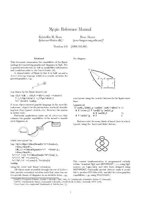
The current implementation is programmed entirely within \standard TEX and METAFONT", i.e., using TEX macros (no \specials) and with fonts designed using METAFONT. Optionally special `drivers' make it possible to produce DVI les with `specials' for extra graphics capabilities, e.g., using PostScript.1
BRICS, Computer Science, Aarhus University (bld. 540), Ny Munkegade, DK{8000 Aarhus C, Denmark. y MPCE (Mathematics dept.), Macquarie University, North Ryde, Sydney, Australia NSW 2109. 1 PostScript is a registered Trademark of Adobe, Inc. 1].
BE 9 q j j j @G S AF B CD j j j j Aj j
Baumer 堡盟视觉传感器应用
n 采用
技术实现强大的360°目标识别功能,充分满足拿放应用要求
n 通过校正透视扭曲和镜头扭曲进行坐标转换
n 可自由定义的处理接口和灵活的结果连接
n 用户等级和密码保护功能,防范未经授权的更改
通过坐标转换,实现精确定位
采用
XF-100 / XF-200,无论零件是否发生旋转,其定位值可输出在
用户定义的坐标处。要输出精确位置,需要在坐标转换过程中对透视扭曲和
以太网,RS485
代码 10 mm
ID-110 3.5
以太网
文本,代码 10 mm
矩阵码 可在任何旋转位置读取矩阵码。质量测定标准为ISO / IEC 15415和AIM DPM-1-2006;读取 结果通过处理接口输出并可与设定值比较。
采用默认参数的典型计算时间(*由于被检零件的特征不同,计算时间可能显著增加)
15 ms* 25 ms* 20 ms* 35 ms*
读取食品包装上“best-before date”(保质期),字 符读取结果通过处理接口输出并与设定值比较。
20 ms* 35 ms*
读取药品包装上的 条形码
读取压铸件上的激光刻写 矩阵码
读取结果通过处理接口输出至机器控制系统。
即使在要求苛刻的应用中,功能强大的
算法仍然能够实现高速读码,例如识别金属表面
上的DataMatrix码、具有透视扭曲、低对比度或码元丢失等情况。
系列
ID-110 多功能读码器
Best before date • Shelf life
为您带来的好处
n 零件无需机械引导 n 快速实施检查任务 n 目标定位功能允许同时检测多个产
品特征
轮廓处理 —— 采用
ARM CoreSight MTB-M0+ Technical Reference Manual

CoreSight™ MTB-M0+Revision: r0p1 Technical Reference ManualCoreSight MTB-M0+Technical Reference ManualCopyright ©2012 ARM. All rights reserved.Release InformationThe following changes have been made to this book.Change historyDate Issue Confidentiality Change19 January 2012A Confidential First release for r0p014 December 2012B Non-Confidential First release for r0p1 Proprietary NoticeWords and logos marked with® or ™ are registered trademarks or trademarks of ARM® in the EU and other countries, except as otherwise stated below in this proprietary notice. Other brands and names mentioned herein may be the trademarks of their respective owners.Neither the whole nor any part of the information contained in, or the product described in, this document may be adapted or reproduced in any material form except with the prior written permission of the copyright holder.The product described in this document is subject to continuous developments and improvements. All particulars of the product and its use contained in this document are given by ARM in good faith. However, all warranties implied or expressed, including but not limited to implied warranties of merchantability, or fitness for purpose, are excluded.This document is intended only to assist the reader in the use of the product. ARM shall not be liable for any loss or damage arising from the use of any information in this document, or any error or omission in such information, or any incorrect use of the product.Where the term ARM is used it means “ARM or any of its subsidiaries as appropriate”.Confidentiality StatusThis document is Non-Confidential. The right to use, copy and disclose this document may be subject to license restrictions in accordance with the terms of the agreement entered into by ARM and the party that ARM delivered this document to.Product StatusThe information in this document is final, that is for a developed product.Web AddressContentsCoreSight MTB-M0+ Technical Reference ManualPrefaceAbout this book (vi)Feedback (ix)Chapter1Introduction1.1About the CoreSight MTB-M0+ ............................................................................... 1-21.2Compliance .............................................................................................................. 1-31.3Features ................................................................................................................... 1-41.4Interfaces ................................................................................................................. 1-51.5Configurable options ................................................................................................ 1-61.6Test features ............................................................................................................ 1-71.7Product documentation and design flow .................................................................. 1-81.8Product revisions ................................................................................................... 1-10Chapter2Functional description2.1About the functions .................................................................................................. 2-22.2Interfaces ................................................................................................................. 2-32.3Operation .................................................................................................................2-6Chapter3Programmers model3.1About the programmers model ................................................................................ 3-23.2Memory model ......................................................................................................... 3-33.3Register summary .................................................................................................... 3-43.4Register descriptions ............................................................................................... 3-8Appendix A Signal descriptionsA.1About the signal descriptions ................................................................................... A-2A.2Clock, reset, and control signals .............................................................................. A-3ContentsA.3AMBA AHB-Lite interface ........................................................................................ A-4A.4SRAM memory interface .......................................................................................... A-6A.5Execution trace interface ......................................................................................... A-7A.6External trace control interface ................................................................................ A-8A.7Debug authentication interface ................................................................................ A-9A.8Miscellaneous signals ............................................................................................ A-10 Appendix B Example Programming SequencesB.1Discovery .................................................................................................................B-2B.2Trace Enable Programming Sequence .................................................................... B-3B.3Trace Disable Programming Sequence ................................................................... B-4 Appendix C RevisionsPrefaceThis preface introduces the CoreSight MTB-M0+Technical Reference Manual. It contains thefollowing sections:•About this book on page vi.•Feedback on page ix.About this bookThis book is for the CoreSight Micro Trace Buffer for the Cortex™-M0+ processor, theCoreSight MTB-M0+ macrocell.Product revision statusThe r n p n identifier indicates the revision status of the product described in this book, where:r n Identifies the major revision of the product.p n Identifies the minor revision or modification status of the product.Intended audienceThis book is written for:•System designers, system integrators, and verification engineers.•Software developers who want to use the MTB.Using this bookThis book is organized into the following chapters:Chapter1 IntroductionRead this chapter for an introduction to the MTB and its features.Chapter2 Functional descriptionRead this chapter for a description of the functionality of the MTB.Chapter3 Programmers modelRead this chapter for a description of the MTB programmable registers andinformation for programming the MTB.Appendix A Signal descriptionsRead this for a description of the signals in the MTB.Appendix B Example Programming SequencesRead this for a description of some example programming sequences for theMTB.Appendix C RevisionsRead this for a description of the technical changes between released issues of thisbook.GlossaryThe ARM Glossary is a list of terms used in ARM documentation, together with definitions forthose terms. The ARM Glossary does not contain terms that are industry standard unless theARM meaning differs from the generally accepted meaning.See ARM Glossary, /help/topic/com.arm.doc.aeg0014-/index.html. ConventionsThis book uses the conventions that are described in:•Typographical conventions on page vii.•Timing diagrams on page vii.•Signals .Typographical conventionsThe following table describes the typographical conventions:Timing diagramsThe figure named Key to timing diagram conventions explains the components used in timing diagrams. Variations, when they occur, have clear labels. You must not assume any timing information that is not explicit in the diagrams.Shaded bus and signal areas are UNDEFINED , so the bus or signal can assume any value within the shaded area at that time. The actual level is unimportant and does not affect normaloperation.Key to timing diagram conventionsSignalsStylePurpose italicIntroduces special terminology, denotes cross-references, and citations.boldHighlights interface elements, such as menu names. Denotes signal names. Also used for terms in descriptive lists, where appropriate.monospaceDenotes text that you can enter at the keyboard, such as commands, file and program names, and source code.monospace Denotes a permitted abbreviation for a command or option. You can enter the underlined text instead of the fullcommand or option name.monospace italic Denotes arguments to monospace text where the argument is to be replaced by a specific value.monospace bold Denotes language keywords when used outside example code.<and>Encloses replaceable terms for assembler syntax where they appear in code or code fragments. For example:MRC p15, 0 <Rd>, <CRn>, <CRm>, <Opcode_2>SMALL CAPITALS Used in body text for a few terms that have specific technical meanings, that are defined in the ARM glossary .For example, IMPLEMENTATION DEFINED , IMPLEMENTATION SPECIFIC , UNKNOWN , and UNPREDICTABLE .The signal conventions are:Signal level The level of an asserted signal depends on whether the signal isactive-HIGH or active-LOW. Asserted means:•HIGH for active-HIGH signals.•LOW for active-LOW signals.Lower-case n At the start or end of a signal name denotes an active-LOW signal. Additional readingThis section lists publications by ARM and by third parties.See Infocenter, , for access to ARM documentation.ARM publicationsThis book contains information that is specific to this product. See the following documents forother relevant information:•CoreSight MTB-M0+ Implementation and Integration Manual (ARM DIT 0031).•Cortex-M0+ Technical Reference Manual (ARM DDI 0484).•AMBA® 3 AHB-Lite™ Protocol Specification (ARM IHI 0033).•CoreSight Architecture Specification (ARM IHI 0029).•ARM v6-M Architecture Reference Manual (ARM DDI 0419).FeedbackARM welcomes feedback on this product and its documentation.Feedback on this productIf you have any comments or suggestions about this product, contact your supplier and give:•The product name.•The product revision or version.•An explanation with as much information as you can provide. Include symptoms anddiagnostic procedures if appropriate.Feedback on contentIf you have comments on content then send an e-mail to errata@. Give:•The title.•The number, ARM DDI 0486B.•The page numbers to which your comments apply.• A concise explanation of your comments.ARM also welcomes general suggestions for additions and improvements.NoteA RM tests the PDF only in Adobe Acrobat and Acrobat Reader, and cannot guarantee thequality of the represented document when used with any other PDF reader.Chapter1IntroductionThis chapter introduces the CoreSight MTB-M0+ and its features. It contains the followingsections:•About the CoreSight MTB-M0+ on page1-2.•Compliance on page1-3.•Features on page1-4.•Interfaces on page1-5.•Configurable options on page1-6.•Test features on page1-7.•Product documentation and design flow on page1-8.•Product revisions on page1-10.1.1About the CoreSight MTB-M0+The CoreSight MTB-M0+ (MTB), provides a simple execution trace capability to theCortex-M0+ processor. The MTB is not intended to be competitive with an ARM EmbeddedTrace Macrocell (ETM™) or Program Trace Macrocell (PTM™) trace solution.1.2ComplianceThe MTB complies with, or implements, the specifications described in:•Advanced Microcontroller Bus Architecture.•Debug authentication interface.This TRM complements architecture reference manuals, architecture specifications, protocolspecifications, and relevant external standards. It does not duplicate information from thesesources.1.2.1Advanced Microcontroller Bus ArchitectureThis MTB complies with the AMBA 3 AHB-Lite protocol. See the AMBA 3 AHB-Lite Protocol.1.2.2Debug authentication interfaceThis MTB complies with the CoreSight authentication interface. See the CoreSight ArchitectureSpecification.1.3FeaturesThe MTB features and benefits are:•Provision of program flow tracing for the Cortex-M0+ processor.•Very small area.•Power reduction features.•MTB SRAM can be used for both trace and general purpose storage by the processor.•MTB SRAM size is configurable at implementation time.•The position and size of the trace buffer in SRAM is configurable by software.•External hardware can control trace start/stop.•CoreSight compliant.1.4InterfacesThe three main interfaces on the MTB are:•AHB-Lite slave interface.•Processor execution trace interface.•Synchronous SRAM master interface.1.4.1AHB-Lite slave interfaceThe MTB AHB-Lite interface provides access to two memory regions for:•The Special Function Registers (SFRs).•The SRAM.HSELSFR selects the address space for the Special Function Registers and HSELRAM selectsthe address space for the SRAM. See AMBA AHB-Lite interface on page A-4 for moreinformation.1.4.2Processor execution trace interfaceThe processor execution trace interface transfers the execution information from the processorto the MTB. See Execution trace interface on page A-7 for more information. The MTB formatsinformation, received from this interface, into trace packets and writes it into the MTB SRAM.1.4.3Synchronous SRAM master interfaceThe SRAM interface connects to the MTB SRAM, that is used to store the trace packetinformation formatted by the MTB.The MTB also operates as a simple AHB-Lite SRAM bridge. The processor has read and writeaccess to the entire MTBSRAM address space using the AHB-Lite interface. This enables theprocessor to access the trace packet information and also to store program and data informationin the SRAM.1.5Configurable optionsTable 1-1 shows the MTB configurable options available at implementation time.Table 1-1 MTB configurable optionsFeatureConfigurable option SRAM address width(AWIDTH)aa.Because the SRAM interface is 32-bits wide, the actualwidth of the SRAM address bus is AWIDTH-2. SeeTable A-3 on page A-6.5-32 er/Privileged supportPresent or absent.Reset all registers Present or absent.1.6Test featuresThe MTB has no test features, because the necessary DFT logic is inserted automatically, duringimplementation by your EDA tools.1.7Product documentation and design flowThis section describes the MTB books and how they relate to the design flow. It includes:•Documentation.•Design flow.See Additional reading on page viii for more information about the books described in thissection. For information on the relevant protocols, see Compliance on page1-3.1.7.1DocumentationThe MTB documentation is as follows:Technical Reference ManualThe Technical Reference Manual (TRM) describes the functionality and theeffects of functional options on the behavior of the MTB. It is required at allstages of the design flow. The choices made in the design flow can mean thatsome behavior described in the TRM is not relevant. If you are programming theMTB then contact:•The implementer to determine:—The build configuration of the implementation.—What integration, if any, was performed before implementing theMTB.•The integrator to determine the pin configuration of the device that you areusing.Integration and Implementation ManualThe Implementation and Integration Manual (IIM) describes:•The available build configuration options and related issues in selectingthem.•How to configure the Register Transfer Level (RTL) with the buildconfiguration options.•How to integrate the MTB into a SoC. This includes describing the pins thatthe integrator must tie off to configure the macrocell for the requiredintegration.•The processes to sign off the integration and implementation of the design.The IIM is a confidential book that is only available to licensees.1.7.2Design flowThe MTB is delivered as synthesizable RTL. Before it can be used in a product, it must gothrough the following processes:ImplementationThe implementer configures and synthesizes the RTL to produce a netlist.Integration The integrator connects the implemented design into a SoC. This includesconnecting it to a memory, processor and AHB-Lite bus.ProgrammingThis is the last process. The tools developer creates the software required toconfigure and initialize the MTB, and tests the required debug software.Each process:•Can be performed by a different party.•Can include implementation and integration choices affect the behavior and features of the MTB.Typically, a single design team integrates the MTB into a SoC before synthesizing the complete design. Alternatively, the team can synthesise the MTB on its own or partially integrated, to produce a macrocell that is then integrated, possibly by a separate team.The operation of the final device depends on:Build configurationThe implementer chooses the options that affect how the RTL source files arepre-processed. These options usually include or exclude logic that affects one ormore of the area, maximum frequency, and features of the resulting macrocell. Configuration inputsThe integrator configures some features of the MTB by tying inputs to specificvalues. These configurations affect the start-up behavior before any softwareconfiguration is made. They can also limit the options available to the software. Software configurationThe programmer configures the MTB by programming particular values intoregisters. This affects the behavior of the MTB.NoteT his manual refers to implementation-defined features that are applicable to build configuration options. Reference to a feature that is included means that the appropriate build and pin configuration options are selected. Reference to an enabled feature means one that has also been configured by software.1.8Product revisionsThis section describes the differences in functionality between product revisions:r0p0 First release.r0p1 ECOREVNUM is in the Peripheral ID3 register instead of the Peripheral ID2register.Chapter2Functional descriptionThis chapter describes the functionality of the MTB. It contains the following sections:•About the functions on page2-2.•Interfaces on page2-3.•Operation on page2-6.2.1About the functionsFigure2-1 shows the main interfaces on the MTB and how they are connected in a simpleCortex-M0+ based system.Figure2-1 MTB system diagram When enabled, the MTB records changes in program flow, reported by the Cortex-M0+processor over the execution trace interface. This information is stored as trace packets in theSRAM. An off-chip debugger can extract the trace information using the DAP to read the traceinformation from the SRAM, over the AHB-Lite interface. The debugger can then reconstructthe program flow from this information.The processor accesses the SRAM using the AHB-Lite interface. The MTB simultaneouslystores trace information into the SRAM, and gives the processor access to the SRAM. The MTBensures that trace write accesses have priority over processor accesses.The MTB does not:•Include any form of load/store data trace capability.•Include tracing of any other information.2.2InterfacesThis section describes the MTB interfaces. it contains:•Clock and reset interface on page2-4.•AHB-Lite interface on page2-4.•Execution trace interface on page2-4.•External trace enable interface on page2-5.•SRAM interface on page2-5.•Debug authentication interface on page2-5.Figure2-2 shows the interface details.Figure2-2 MTB interfaces2.2.1Clock and reset interfaceThe clock and reset interface consists of the HCLK, RESETn and IDLE signals. The IDLEsignal can be used to gate HCLK outside the MTB to save power. See Clock, reset, and controlsignals on page A-3 for additional information.2.2.2AHB-Lite interfaceThe following sections describe the AHB-Lite interface used by the MTB:•Wait state behavior.•Buffering.The MTB AHB-Lite interface provides access to two memory regions, one for the SpecialFunction Registers and the other for the SRAM. The memory regions are selected by theHSELSFR and HSELRAM inputs respectively. Only one of these select inputs can be HIGHat a time. If they are both HIGH at the same time the behavior is UNPREDICTABLE.SFR accesses must be word accesses. SRAM accesses can be either byte, halfword or wordaccesses.See the AMBA 3 AHB-Lite Protocol Specification for more information.Wait state behaviorSRAM accesses from the AHB-Lite interface occur with zero wait states when there is no tracedata being written to the SRAM.Trace packet write access to the SRAM take priority over access from the AHB-Lite interface.Therefore, one or more wait states can be inserted into the AHB-Lite accesses if traceinformation is simultaneously written to the SRAM.Special Function Register, SFR, accesses always occur with zero wait states.BufferingThe MTB AHB-Lite interface can buffer two address phases and one data write phase forSRAM accesses. This enables:•AHB-Lite accesses to the SRAM to occur at the same time as a trace packet is written tothe SRAM.•AHB-Lite read access to the SRAM to follow an AHB-Lite write access without insertingwait states.•AHB-Lite write access to be adapted to the SRAM interface protocol.2.2.3Execution trace interfaceThe execution trace interface consists of the IAXEN, IAEXSEQ, IAEX[30:0], ATOMIC, andEDBGRQ signals.Optionally, you can program the MTB to use the EDBGRQ output to request the processor toenter the halt state when the trace buffer is full. This avoids loss of trace information. See FLOWRegister on page3-11.2.2.4External trace enable interfaceThis interface enables external control over when tracing starts and stops. It consists of theTSTART and TSTOP signals. See Trace start and stop on page2-7 and External trace controlinterface on page A-8.2.2.5SRAM interfaceThis is a synchronous interface to the SRAM. The MTB uses this interface for trace andAHB-Lite accesses to the SRAM. See MTB execution trace packet format on page2-6 andSRAM memory interface on page A-6.2.2.6Debug authentication interfaceThis interface permits trace to be disabled for security purposes. See also Debug authenticationinterface on page A-9 for signal information.Table2-1 shows a summary of the authentication behavior.Table2-1 Debug authentication interface behaviorDBGEN NIDEN Execution traceenabledSRAM accessallowed from AHBSFR accessallowed from AHBEDBGRQ00No Yes Yes001Yes Yes Yes01X Yes Yes Yes MASTER.HALTREQ2.3OperationThis section describes the operation of the MTB. It contains the following sections:•MTB execution trace packet format.•Trace start and stop on page2-7.2.3.1MTB execution trace packet formatThe execution trace packet consists of a pair of 32-bit words that the MTB generates when itdetects the processor PC value changes non-sequentially. A non-sequential PC change can occurduring branch instructions or during exception entry.NoteT he processor can cause a trace packet to be generated for any instruction.Figure2-3 shows the signal combination that detects a non-sequential PC change.Figure2-3 MTB non-sequential PC diagram Figure2-4 shows how the execution trace information is stored in memory as a sequence ofpackets.Figure2-4 MTB execution trace storage format The first, lower addressed, word contains the source of the branch, the address it branched from.The value stored only records bits[31:1] of the source address, because Thumb instructions areat least halfword aligned. The least significant bit of the value is the A-bit. The A-bit indicatesthe atomic state of the processor at the time of the branch, and can differentiate whether thebranch originated from an instruction in a program, an exception, or a PC update in Debug state.When it is zero the branch originated from an instruction, when it is one the branch originatedfrom an exception or PC update in Debug state. This word is always stored at an even wordlocation.The second, higher addressed word contains the destination of the branch, the address itbranched to. The value stored only records bits[31:1] of the branch address. The least significantbit of the value is the S-bit. The S-bit indicates where the trace started. An S-bit value of 1indicates where the first packet after the trace started and a value of 0 is used for other packets.Because it is possible to start and stop tracing multiple times in a trace session, the memorymight contain several packets with the S-bit set to 1. This word is always stored in the nexthigher word in memory, an odd word address.When the A-bit is set to 1, the source address field contains the architecturally-preferred returnaddress for the exception. For example, if an exception was caused by an SVC instruction, thenthe source address field contains the address of the following instruction. This is different fromthe case where the A-bit is set to 0. In this case, the source address contains the address of thebranch instruction.For an exception return operation, two packets are generated:•The first packet has the:—Source address field set to the address of the instruction that causes the exceptionreturn, BX or POP.—Destination address field set to bits[31:1] of the EXC_RETURN value. See theARM v6-M Architecture Reference Manual.—The A-bit set to 0.•The second packet has the:—Source address field set to bits[31:1] of the EXC_RETURN value.—Destination address field set to the address of the instruction where executioncommences.—A-bit set to 1.2.3.2Trace start and stopTracing is enabled when the MASTER.EN bit in the Master Trace Control Register is 1. Thereare various ways to set the bit to 1 to start tracing, or to 0 to stop tracing. See MASTER Registeron page3-9.You can control trace externally using the TSTART and TSTOP signals or using the MasterTrace Control Register, see TSTART and TSTOP signals on page2-8. You can program the MTBto stop tracing automatically when the memory fills to a specified watermark level or you canstart or stop tracing by writing directly to the MASTER.EN bit, see MASTER Register onpage3-9. If you do not use the watermark mechanism, and the trace buffer overflows, then thebuffer wraps around overwriting previous trace packets.If more than one source attempts to modify the MASTER.EN bit value in the same cycle thenthe following priority order is used to determine which value is accepted. The lowest number isthe higher priority.1.Watermark stop.2.Software write to the MASTER.EN bit.3.TSTART and TSTOP signals.Note•If you use the watermark auto stop feature to stop trace, you cannot restart trace untilsoftware clears the watermark auto stop. You can achieve this in one of the followingways:—By setting the POSITION.POINTER field to point to the beginning of the tracebuffer. See POSITION Register on page3-8.—By setting the FLOW.AUTOSTOP bit to 0. See FLOW Register on page3-11.。
ROHM BD34301EKV 32位D A转换器IC说明书

32bit D/A Converter I C ‘BD34301EKV’for Hi-Fi Audio EquipmentApril 1, 2021ROHM Co., Ltd.Marketing Communications Dept.*MUS-IC TM is a trademark or registered trademark of ROHM Co., Ltd.*Please note that this document is current as of the date of publicationROHM's first, most advanced MUS-IC TM series DAC chip enablesexpressive playback of classical musicAudio SoCSpeakersHigh Fidelity Audio Equipment and ROHM’s ApproachRadio/TV TunerRecording Media (Audio Source)Power Supply ICReleased Sep 2017We are developing a variety of products for high-fidelity audio equipmentAnalog Signal Digital Signal Control SignalMedia DecoderAmplifierAnalog DesignAudio DeviceSound Processor (Digital)MCUD/A ConverterSound Processor (Analog)Sound ProcessorReleased Oct 2016AmplifierReleased Mar 2018Digital DesignSpeakersClass D Speaker AmplifierClass AB Speaker AmpSupports high-fidelity, high-res audioSupports high-res audioSupports high-fidelity, high-res audio Supports high-fidelity, high-res audio12345Listening Evaluation ResultsConventional New ProductClarityRealityExpansionResolutionLocalizationBass feeling stereotacticDistortion feelingPowerfulnessAchieving Optimum Sound Quality Using ROHM’s Vertically Integrated Production System and Sound Quality Design TechnologyIC Layout, PhotomaskManufacturingWafer Formation ProcessDie and Lead FrameFinished IC ChipROHM’s Vertically Integrated Production SystemThe parameters in each process confirmedto have an effect on sound quality are shown belowLead FrameIC LayoutBonding WirePackageAt various steps in our vertically integrated production process, we have identified 28 parametersthat affect sound quality and adjusted them one by one to create the desired soundEx) Sound Processors for Hi-Fi AudioPlayer (Audio Source)PlayerPreamp (Volume Control)Sound ProcessorMain AmpPower AmpSpeakersIntegrated AmpMaintains information even at low volumeCheck sound quality through actual listening evaluation basedon a set of indicatorsPackageCircuit Design12 parameters6 parameters6 parameters1 parameter3 parametersVerify the sound quality in a dedicated listening room (At the Yokohama Technology Center)ROHM’s High -End Audio Device Brand: ROHM Musical Device [MUS-IC]For more information, please visit ROHM’s Musical Device ‘MUS -IC TM ’ web page.https:///mus-ic/MUS-IC TMCreated by combining the ‘Sound Quality Design Technology ’with ROHM’s corporate mission of ‘Quality First ’, ‘Vertically Integrated Production System ’, and ‘Contribution to the Musical Culture ’, MUS-IC TM (official name: ROHM Musical Device‘MUS -IC TM ’) is an audio device brand that represents the ultimate IC solutions developed by ROHM’s team of experienced and dedicated engineers.Quality FirstQ ualityContributing to Music CultureF or everyonemoved by musicSound QualityDesign TechnologyS oundVertically Integrated Production SystemC raftsmanshipDevelopment ConceptMUS-IC TMProduct OverviewROHM's first top-shelf MUS-IC TM series of DAC chips enables expressive playback of classical musicKey CharacteristicsNo. of Outputs: 2ch (stereo)Resolution: 32bitSampling Frequency: 32kHz to 768kHzS/N Ratio: 130dB (typ.)THD+N: -115dB (typ.)DSD Clock: 2.8MHz, 5.6MHz,11.2MHz, 22.4 MHzFIR Filter: Preset, Custom, External Segment We will begin selling the BD34301EKV DAC chip along with an evaluationBD34301EKV-EVK-001 Evaluation BoardEnables immediateevaluation of the soundquality of the BD34301EKV Please refer to the evaluation board user’s guide for details.The BD34301EKV delivers superior performance in audio equipment by improving sound quality in ways that cannotbe defined by numerical characteristicsDeliver sound quality characteristics that allow one to hear elementssuch as ‘spatial reverberation’, ‘quietness’, and ‘dynamic range’D/A Conversion Circuit⚫Minimizes the power supplyimpedance of each current segment ⚫Optimized wiring layout⇒Reduces the clock delay (thatdetermines the timing operation of each current segment) as much as possibleDigital Signal Processing Circuit⚫The FIR filter (a key function) isdesigned to faithfully process even the smallest signals⇒Achieves a rejection band attenuation (a filter performance index) of -150dB or lessEfforts to improve sound quality performanceBD34301EKV MUS-IC TM 32bit D/A Converter ICFeature 1: Achieves best-in-class sound quality characteristics ideal for classical musicFeature 2: Customizable digital filter allows designers to tailor the sound to audio equipment The BD34301EKV includes a customizable digital filter -a key feature of the digital signal processing circuit -supporting the creation of the ideal sound sought by audio equipmentmanufacturersFIR Filter Specifications⚫Select from preset / custom / external settings⚫The filter’s calculation coefficients and oversampling rate can alsobe customized with the program function⇒Configure unique digital filters to easily achieve different sound qualitytunings for each audio deviceCustomizable digital filters help reduce development loadand create the ideal sound sought by manufacturersReduce the power supply wiring impedance of each currentsegment as much as possibleSound quality improvement effect: Improved bass power and depth,resulting in better sound range balanceEliminating the common impedance from each current segment to the power supply pin makes it possible to align the matching characteristics of the current segments-120-110-100-90-80-70-60-50-40-30-20-100-100-90-80-70-60-50-40-30-20-10T H D +N (d B )Input Level (dBFS)THD+N vs Input LevelBD34301EKVWiring ImpedanceCurrent SegmentCurrent Segment Current SegmentMinimize clock skew and optimize slew rateSound quality improvement effect: Increased realism and resolution alongwith bassClockCurrent SegmentCurrent SegmentCurrent SegmentCurrent Segment time Level (L→H)Fastest ClockClock WaveformSlowest ClockMinimize clock skew between current segmentsMaterial of bonding wires connecting the chip to the lead frameMinimize stress on chips in IC packagesAu CuSound improvement effect: More natural reverberation , with a more delicateinstrumental toneSelect the best bonding wires material for the device because its material that connecting the device to the lead frame is affected the sound qualityBonding WireSelect the IC package and wafer processing method that minimize stress . At the same time, adopt a completelysymmetrical chip layout for the current segment circuit.Sound improvement effect: Reduced sound peculiarities, resulting in amore natural soundCurrent OutputPins Current OutputPinsChipIC PackageCompletely symmetricalLch Rch 電流セグメントLchRchCurrent Segment Examples of Sound Quality Improvement Effects Based on Sound Quality Design Tech.P . 10© 2021 ROHM Co., Ltd. Sales InformationThe BD34301EKV enables evaluation and adoption for a wide range of customerMUS-IC TM Sales⚫Supporting documents required for evaluation are now available on ROHM’s website:https:///products/audio-video/audio-converters/audio-dacs/bd34301ekv-product/documents⚫An evaluation board (BD34301EKV-EVK-001) is also available together with IC through online distributors Part No: BD34301EKVSales Launch Date: From December 2020Reference Price:$80.5 /pc. (excluding tax)Production Status: In mass production Evaluation Board Sales Part No: BD34301EKV-EVK-001Sales Launch Date: From February 2021Reference Price: Please refer to each online distributor websitePlease consider the BD34301EKV MUS-IC TM 32bit D/A converter IC for your next design Electronic Components and Parts Search | DigiKey ElectronicsSearch results for: bd34301ekv ROHM Semiconductor –Mouserbd34301ekv -Search Results | Farnell DE© 2021 ROHM Co., Ltd.Notes•The content specified herein is for the purpose of introducing ROHM’s products (hereinafter “Products”).•If you wish to use any such Product, please be sure to refer to the specifications, which can be obtained from ROHM upon request.•Great care was taken in ensuring the accuracy of the information specified in this document. However, should you incur any damage arising from any inaccuracy or misprint of such information, ROHM shall bear no responsibility for such damage.•The technical information specified herein is intended only to show the typical functions of and examples of application circuits for the Products.•ROHM does not grant you, explicitly or implicitly, any license to use or exercise intellectual property or other rights held by ROHM and other parties.•ROHM shall bear no responsibility whatsoever for any dispute arising from the use of such technical information.•If you intend to export or ship overseas any Product or technology specified herein that may be controlled under the Foreign Exchange and the Foreign Trade Law, you will be required to obtain a license or permit under the Law.•The content specified in this document is correct as of April 2021.© 2021 ROHM Co., Ltd.P. 12。
A Tutorial on Using the ALSA Audio API(中英文版)

Let us first review the basic design of an audio interface. As an application developer, you don't need to worry about this level of operation - its all taken care of by the device driver (which is one of the components that ALSA provides). But you do need to understand what is going at a conceptual level if you want to write efficient and flexible software.
o Opening The Device o Setting The Parameters o Receiving And Delivering Data Why You Might Want To Forget About All Of This
A Tutorial on Using the ALSA Audio API/ALSA Audio API 使用指南
Both of these are very important for many kinds of audio software, though some programs do not need be concerned with such matters.
What a typical audio application does
Author: Paul Davis Translate: kang_liang Sort out: Zhao lijun Added: Zhao lijun
斑马技术公司DS8108数字扫描仪产品参考指南说明书

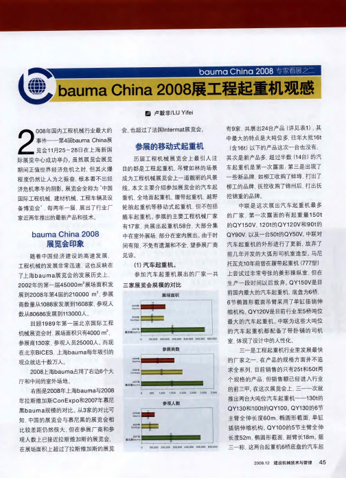
bauma China 2008展工程起重机观感
了很大的提高。 特别是徐工集团.
一
共推出6 个全 地面起重机 产品,
京城重工生产的底盘。 后桥采用 了橡胶悬架, 配备72 3 W的发 8k
动机 车总 重4 t 行驶状 态可 整 8,
基本上形成了 全系列产品, 在最大 吨位、 产品规格、 技术水平和市场
占有 率 上 , 牢 牢巩 固了其 行 业 都
盘。 值得注意的是QY 0 , 2 F 这是一个抚 个厂家, 国内国外各三家。 本次展览会
挖 锦重 推 出的全 新产 品, 目前 行业 内 是 是国内厂家展出全地面起重机最多的一 2 l 级产 品中唯一配 备了5 0E I 节伸 缩臂 的 次 , 应 出国 内全 地面 起重 机技 术 已日 反
N 3 0 R 加藤 在 日 K 0V 。 产和三菱放 弃汽车 飞 猛进 的发展 。
起 重机 底盘 生 产后 , 一直 受到底 盘 问题
2 0 年b u 展览会上起重机臂架如林 0 8 a ma
全 地 面起 重机 一 共 展 出了1 个产 2
的困扰, 最终开始尝试中国一汽生产的 品, 详见表2 与两年前相比较. 。 国产全
是整机 的可靠性和工艺水平, 都有
北起 一 田野推 出的GT7 0 是 这 汽 车起重 机底 盘 主要销 往东 南亚和 中 地面 起 重机 不论 是 吨位 、 多 5E . 技术 水 平, 还
家合资公司生产的最大规格的汽
车起重 机 , 大起 重 量 为7 t 主 最 5, 臂长4 m 4 副臂 1
表2本届b u ia a maCh 参展的全地面起重机 n
协 会 统 计 , 0 6 中国 国产 履带 起 重 20 年 机 的销量 为5 7 最 大吨位 是 中联 在 0 台. 2 0 年上 海 b u 展 览会 上 展 出的 06 a ma
- 1、下载文档前请自行甄别文档内容的完整性,平台不提供额外的编辑、内容补充、找答案等附加服务。
- 2、"仅部分预览"的文档,不可在线预览部分如存在完整性等问题,可反馈申请退款(可完整预览的文档不适用该条件!)。
- 3、如文档侵犯您的权益,请联系客服反馈,我们会尽快为您处理(人工客服工作时间:9:00-18:30)。
iCC展会报道Exhibition Report
bauma
本刊对展
会进行了预览
2007年4月23
举办时间稍晚
因此
由于新建了2个展馆
总面积达到53万m
2
就是关闭了贯穿室外展区的一
条道路
从主展区进入室
b 再一次感受bauma
外展场最北部的区域只能通过拥挤的
人行天桥
人员的流动
要顺畅得多了
例如提供给来自中国
分配给
中国制造商的面积是2004年的5倍
给
日本制造商的是2004年的5倍
来自奥地利
韩国和希腊的参展商提出的参
展面积要求翻了一番
特别
是欧洲市场的重要性
上一届bauma在2004
年举办
(下半月刊)
2007.1-2
iCC
展会报道
Exhibition Report
德国本身对设备供应商也有强大
的吸引力
有3/4是
来自德国
可以说
上届展会有12万观众来自
德国以外的地区
近年来
很多指令将在2007
年生效
新的欧洲Stage IIIA
法规将对使用
19
130kW
它新品有
ZX170W-3
履带式挖掘机ZX160-3
(16t)和ZX180-3(18t)
它的展
台将展出新型C系列挖掘机
23.4t的履带式挖掘机EC160C
以及14.3
EW160C和
EW180C
首批投产的
型号是116kW的
L60F
凯斯将在展会上发布
同时
比如配备159kW发动机的821E轮式装
载机
已经经过本刊
确认
也
并不是bauma上推出的所有新品都是
属于这2个功率段
另外值得注意的是
配
备发动机的土方机械和筑路设备制造商的展台都是最大的
有很多参展商是生产属
虽然没有受到2007年排放法规的影响
该机型的工作级别为10m3
/min
这些功率范围覆盖了很多设备
5t以下的小型挖
掘机
欧洲市场每
年约销售7万台这样的设备
19涵
盖了所谓的涉及到的机械有
13
斗容2m3
标准容量
虽然这些设备的销量不如应用在狭小场地和市政工作的小
型设备那样多
涵盖了路面建设和养
护设备中很多
畅销的设备以及中小型市政工程所用
的设备
在世界也是如此
其中有山猫的
425 ZTS小型无尾挖掘机
将发
布
0.8
ZX10U-2这些
带U的型号都是无尾的意思
包括Roadtec筑路设备和公司制造的破碎筛分
设备
2007.1-2
(下半月刊)
iCC展会报道Exhibition Report
52
旅行和宾馆
bauma已与Smart and More
GmbH旅行社达成协议
该公司可
以帮您预定宾馆飞
机/火车/
汽车
smartfairs@sam-hh.de
电话
一些国家的观众需要签证才能进入德
国沙特
阿拉伯印度尼西亚和
泰国
如果需要展会的邀请函
具
新技术
一个有趣的领域是发动机制造
商
他们正在瞄准Stages IIIB和
Stages IV
这些标准将会苛刻
得多
另外还要进一步减少污染气体的排放
比
如在非公路机械中引进particulate fil-
ters和after-treatment systems技术
在2006年法国的Intermat
展会上
在理论上
生物能
更多的公司加入到这个趋势
中来将是非常有益的
关注下个月
总的来说
日立的新型19吨
级的轮式挖掘机
ZX190W
图示为将在展会上展出
的沃尔沃
EW140C
请浏览
您将收到您的观众入场券
1天参观券28.60美元
3天参观券58.50美元
全程参观券
75.40美元
团购会享受折扣
2007年4月23-29日
开展时间
上午9.30
上午8.30
上午9.30
慕尼黑新国际博览中心
主办方
电话
www.bauma.de
如何到达展馆
如果乘地铁
在地铁U2线上
30
运行到午夜
在bauma 2007的开馆和闭馆时
段地铁可以直接到达慕
尼黑新国际博览中心
/ICM
Messestadt West
在展会期间
设有
为观众服务的bauma
信息咨询台
凭参观券
还可以免费乘坐从
机场到展场的大巴
慕尼黑新国际博览中心
和ICM位于A94公路上
Munchen-Riem出口(5号出
口)和Moosfeld出口(4号出口)可直接到达
再一次感受bauma
刊名:
建筑机械(下半月)
英文刊名:INTERNATIONAL CONSTRUCTION CHINA
年,卷(期):2007(1)
本文链接:/Periodical_jzjx-xby200701012.aspx。