BRG 457-N
457双桥中桥

重汽总成图号所属总成序号青特图号重汽图号名称单位专用Z通用T易损C常用B非常用A安全件A功能件G结构件J装饰件ZQT457S648-2502000WG7112330720+001/2中桥主减总成(i=4.444)件T A G182502170K5HWG7112330722+021/2贯通轴油封总成件T C G 2502166K5HA01WG7112330720+002/2贯通轴凸缘总成件T B G 192502166K5H WG7112330722+022/2贯通轴凸缘总成件T B G 202502071K5H WG7112330722+023/2螺母-紧固主动锥齿轮突缘件T B G 212403084-4EWG7112330722+024/2半轴垫密片件T B G 2403081K5HB1WG7112330722+025/2半轴(左)件T B G 2403082K5HB1WG7112330722+026/2半轴(右)件T B G Q40316WG7112330722+027/2弹簧垫圈件T B G 2403083-4EWG7112330722+028/2半轴螺栓件T B G QT457S648-3530010WG7112330720+003/2后制动气室件T B A QT457S233-3530010WG7112330722+029/2后制动气室件T B A2223Q40308WG7112330724+002/2弹簧垫圈件T B G CQ1500816WG7112330724+003/2螺栓-止动片件T B G(二)、Q40312WG7112330722+030/2弹簧垫圈件T B G CQ1501235WG7112330722+031/2螺栓-止动片件T B G 42403072A31WG7112330722+032/2止动片件T B G 52403071D1H WG7112330722+033/2调整环件T B G 6594A/592A WG7112330722+034/2轴承件T C G 32503010M5H(I=5.286)WG7112330722+035/2差速器总成件T B G 2503010N5H(I=5.833)WG7112330723+002/2差速器总成件T B G 2503010L5H(i=4.875)WG7112330741+002/2差速器总成件T B G 2503010P5H(I=6.333)WG7112330724+004/2差速器总成件T B G 2503010K5H(i=4.444)WG7112330720+004/2差速器总成件T B G 842708KWG7112330722+036/2主动圆锥齿轮圆柱滚子轴承总成件T C G 92502015K5H WG7112330722+037/2中桥主减速器壳总成件T A G CQ1501440T WG7112330722+038/2螺栓-紧固圆柱齿轮外壳件T B G Q40314WG7112330722+039/2弹簧垫圈件T B G 112502045K5H WG7112330722+040/2主动锥齿轮轴承座件T B G 122502097-99K5H WG7112330722+041/2调整垫片件T B G 13Q1801440WG7112330722+042/2自锁螺栓-轴承座件T B G 142502122K5H WG7112330722+043/2堵盖-圆柱齿轮外壳件T B J CQ1501020WG7112330722+044/2螺栓-紧固圆柱齿轮外壳堵盖件T B G Q40310WG7112330722+045/2弹簧垫圈件T B G 162507010K5H WG7112330722+046/2轴间差速器及外壳总成件T A G 172502161K5H WG7112330722+047/2贯通轴件T B G 182508052K5H WG7112330722+048/2齿套-轴间差速锁件T B G 192502124K5H WG7112330722+049/2垫密片-堵盖件T C J 202502107K5H WG7112330722+050/2主动圆柱齿轮件T B G 2130215WG7112330722+051/2主动圆柱齿轮轴承件T C G 222502126K5H WG7112330722+052/2主动圆柱齿轮轴承座件T B G 232507013K5H WG7112330722+053/2垫密片-轴间差速器壳垫片件T B G CQ1501455WG7112330722+054/2螺栓-紧固轴间差速器外壳件T B G Q40314WG7112330722+055/2弹簧垫圈件T B G CQ1501030WG7112330722+056/2螺栓-紧固外壳件T B G Q40310WG7112330722+057/2弹簧垫圈件T B G 262508013-52WG7112330722+058/2垫密片-差速锁外壳件T B J QT457S623-2511000WG7112330720+005/2轴间差速锁总成件T B G 2508010K5H WG7112330722+059/2轴间差速锁总成件T B G7101524252722403053D1H WG7112330722+060/2垫片-半轴齿轮件T C G 32403051D1HB1WG7112330722+061/2半轴齿轮件T B G 42403061D1H WG7112330722+062/2十字轴件T B G 52403058D1H WG7112330722+063/2垫片-行星齿轮件T C G 62403056D1HWG7112330722+064/2行星齿轮件T B G 2502940L5H(I=4.875)WG7112330741+003/2中桥主从动锥齿轮(I =4.875)套T B G 2502940N5H(I=5.833)WG7112330743+001/2中桥主从动锥齿轮(I =5.833)套T B G 2502940K5H(I=4.444)WG7112330720+006/2中桥主从动锥齿轮(I =4.444)套T B G 2502940P5H(6.333)WG7112330724+005/2中桥主从动锥齿轮(I =6.333)套T B G 2502940M5H(I=5.286)WG7112330722+065/2中桥主从动锥齿轮(I =5.286)套T B G 82403015D1HB1WG7112330722+066/2差速器外壳总成(4.444-5.286)套T B G 92402063D1HWG7112330722+067/2螺栓-紧固从动锥齿轮与差速器左壳件TBG(三)、差速器组件7102403023D1H WG7112330722+068/2螺栓-紧固差速器壳件T B G29278/9220WG7112330722+069/2主动圆锥滚子轴承总成件T C G 32502049K5HWG7112330722+070/2主动锥齿轮轴承座件T B G 42402081D1HB1-2402089D1HB1WG7112330722+071/2调整垫片-主动锥齿轮轴承件T B G 530613B WG7112330722+072/2主动圆锥滚子轴承总成件T C G 62502108K5H WG7112330722+073/2从动圆柱齿轮件T B G 72402071D1HWG7112330722+074/2螺母-紧固从动圆柱齿轮件TBG(四)、中桥主动锥齿轮轴承座总成12507050K5H WG7112330722+075/2轴间差速器总成件T B G 2CQ61803WG7112330722+076/2放油螺塞件T B J 32507011K5H WG7112330722+077/2轴间差速器壳总成件T A G 46313K WG7112330722+078/2轴间差速器轴承件T C G 5Q430140WG7112330722+079/2挡圈-轴间差速器件T B J 62402055D1H WG7112330722+080/2轴间差速器油封总成件T C G 72402067D1HWG7112330722+081/2挡尘罩-轴间差速器油封件T B G 8QT457D285-2402060WG7112330722+082/2中桥轴间差速器凸缘总成件T B G 82402065D1HB01WG7112331863+003/2中桥轴间差速器凸缘总成件T B G 92402071D1HWG7112330722+083/2中桥轴间差速器凸缘螺母件T B G(五)、轴间差速器及外壳组件112507055K5H WG7112330722+093/2轴间差速器壳总成1QT457S2-2406030WG7112330722+094/2指示灯开关件T B G 22508011-52WG7112330722+095/2外壳-差速锁件T B G 32508041K5H WG7112330722+096/2拨叉件T B G 4Q5280516WG7112330722+097/2弹性圆柱销件T B G 62508027-52WG7112330722+098/2拨叉轴件T B G 72508032-52WG7112330722+099/2回位弹簧件T B G 82508026-52WG7112330722+100/2活塞件T B G 9Q7343150WG7112330722+101/2O型橡胶密封圈-轴间差速锁件T B G 10QT457S623-2511021WG7112330722+102/2气缸-差速锁件T B G 11CQ63505WG7112330722+103/2管接头-气缸件T B G 12Q40308WG7112330722+104/2弹簧垫圈件T B G 13CQ1500825WG7112330722+105/2螺栓-紧固气缸件T B G(七)、轴间差速锁组件(八)、1Q150B1016WG7112330722+106/2螺栓-紧固蹄片轴挡板用件T B G 23501087-4E WG7112330722+107/2锁片件T B G 33501086-4E WG7112330722+108/2蹄片轴挡板件T A G 43502082-4E WG7112330722+109/2后制动蹄支承销件T A G 53502436-4E WG7112330722+110/2后制动蹄回位弹簧件T B G 6Q40306WG7112330722+111/2弹簧垫圈件T B G 7CQ1500610WG7112330722+112/2螺栓-紧固挡尘盘与制动支架用件T B G83501034-02WG7112330722+113/2堵塞-挡尘盘检查孔件T A G 93501156-01WG7112330722+114/2调整垫片-刹车凸轮件T B G 3502205-A0B WG7112330720+007/2后制动调整臂总成件T B A 3502205-1HA01WG7112330722+115/2后制动调整臂(手动 左)件T B A 3502210-1HA01WG7112330722+116/2后制动调整臂(手动 左)件T B A 113501158-01WG7112330722+117/2凸轮垫圈件T B G 123501157-01WG7112330722+118/2调整垫片-后刹车凸轮件T B G 13Q5006035WG7112330722+119/2开口销件T B G 143502407-4E WG7112330722+120/2后制动摩擦片件T C A 15CQ1501635T WG7112330722+121/2螺栓-紧固后制动支架用件T B J 3502031-1H WG7112330722+122/2后制动左上(右下)挡尘盘件T A G 3502032-1H WG7112330722+123/2后制动左下(右上)挡尘盘件T A G 183502039-4E WG7112330722+124/2锁片件T B G 3502151-5H WG7112330740+004/2后左凸轮轴件T B G 3502152-5H WG7112330740+005/2后右凸轮轴件T B G 3502151-A0A WG7112330722+125/2后制动凸轮轴(左)件T B G 3502152-A0A WG7112330722+126/2后制动凸轮轴(右)件T B G 203501158-01WG7112330722+127/2凸轮垫圈件T B G 3502125-5H WG7112330740+006/2中桥左气室支架件T B G 3502130-5H WG7112330740+007/2中桥右气室支架件T B G S3502127-A0A WG7112330722+128/2后气室支架(左)件T B G S3502128-A0A WG7112330722+129/2后气室支架(右)件T B G 22Q151B1435WG7112330722+130/2螺栓-紧固后制动凸轮支架用件T B J 23Q40314WG7112330722+131/2弹簧垫圈件T B G1710192113501408-4EWG7112330722+132/2后制动摩擦片铆钉件T B G 23502407-4E WG7112330722+133/2后制动摩擦片件T C A 33502390-4E WG7112330722+134/2后制动蹄总成件T B A 4CQ34016WG7112330722+135/2螺母-紧固柱销用件T B G 53501393-02WG7112330722+136/2后制动蹄回位弹簧销件T A G 63501397-02WG7112330722+137/2后制动蹄滚轮件T B G 73501398-02WG7112330722+138/2后制动蹄滚轮轴件T A G 83501396-4E WG7112330722+139/2后制动蹄衬套件T B J 9Q5006035WG7112330722+140/2开口销件T B G(九)、后制动蹄片组件3502571-4EA1WG7112330722+141/2后制动鼓件T B A 3502571-4E WG7112331743+001/2后制动鼓件T B A 23104045-4EB1WG7112330722+142/2后轮毂油封件T C G 330621WG7112330722+143/2后轮毂内轴承总成件T C G 4QT457D1-3104059WG7112330722+144/2螺母件T B J 5ZL3104051B116-F-2WG7112330722+145/2后车轮螺栓件T B A 67819EWG7112330722+146/2后轮毂外轴承总成件T C G 3104011-4ED3WG7112331743+002/2轮毂件T A A 3104011-4EB1WG7112330722+147/2轮毂件T A A1(十)、后制动鼓组件7QT457S650-2500001QT457S651-2500001QT457S652-2500001QT457S648-2500001QT457S661-2500001QT457S662-2500001QT457S663-2500001QT457S664-2500001QT457S711-2500001QT457S929-2500001QT457S709-2500001QT457S727-2500001WG711233072 2/2(5.286)WG7112330723/2(5.833)WG7112330724/2、WG7112330730/2(6.333)WG7112330720/2、WG7112330726/2WG7112330740/2、WG7112330746/2WG7112330741/2、WG7112330747/2WG7112330742/2、WG7112330748/2WG7112330743/2、WG7112330749/2WG7112331743/2、WG7112331749/2WG7112331863/2;WG7112331869/2WG7112331741/2、WG7112331747/2WG7112331848/2、WG7112331842/2备注单台用量11。
l245n化学成分

l245n化学成分
L245N钢是石油和天然气工业中常用的一种管线钢。
它主要由碳、锰、硅、磷、硫等
元素组成。
其中,碳是最主要的元素,其含量通常为0.22%~0.28%。
锰是次要的合金元素,其含量通常为1.2%~1.5%。
硅和磷的含量通常为0.03%~0.06%。
硫的含量通常低于0.003%,以保证管线钢的耐腐蚀性能。
除了上述元素外,L245N钢中还包含一些微量元素,如铜、钒、铬、钛、锆、铝等。
这些元素虽然含量极少,但却对管线钢的性能起着重要的影响。
例如,铜的加入可提高钢
的耐腐蚀性能;钒、铬、钛的加入可提高钢的强度和韧性;锆的加入可提高钢的热稳定性
和抗氧化性;铝的加入可提高钢的耐蚀性和抗氧化性。
此外,在生产L245N钢中,还需要加入一些合金化合物,如钒铁、铬铁、锰硅等。
这
些合金化合物不仅能够提高钢的强度和韧性,还能够改进钢的冷加工和热加工性能。
总之,L245N钢的化学成分是十分复杂的,其中每个元素的含量和比例都能够对钢的
性能产生重要的影响。
因此,在生产L245N钢时,需要严格控制每个元素的含量和比例,
以确保钢的各项性能符合要求。
n457资料
&RQWDFW &RQYHQRU ,62,(& -7& 6& :* 0U (0HODJUDNLV $FKDUQRQ .DWR 3DWLVVLD $7+(16 ± *5((&( 7HO )D[ (PDLO HHP#HORWJU
SOURCE : PROJECT: STATUS :
ITTF JTC 1.02.20.13 The attached table of replies indicates that this DIS has been approved. In accordance with ResolutionM07.24 adopted at the 7WK SC 2 plenary meeting held in Crete, Greece, 1997-07-08/09, the project editor is requested to prepare a disposition of comment report and a revised text For SC 2 consideration and action
元器件交易网
,62,(&-7&6&:*1
元器件交易网
,62,(&-7&6&:*1
元器件交易网
,62,(&-7&6&:*1
元器件交易网
,62,(&-7&6&:*1
元器件交易网
,62,(&-7&6&:*1
Date : 1998-04-15
,62,(&-7&6&:* ELWDQGELWFRGHVDQGWKHLUH[WHQVLRQ 6(&5(7$5,$7(/27
Bell 412CF-23-73 尾旋驱动杠轴集装箱检查说明说明书

Applicability of this bulletin to any spare part shall be determined prior to its installation on an affected helicopter.Table 1. Corresponding Replacement Part NumbersLegacy Part Number Current Production Part Number412-040-620-101 412-040-620-105412-040-620-103 412-040-620-107412-040-621-105 412-040-621-109412-040-621-107 412-040-621-111 APPROVAL:The engineering design aspects of this bulletin are FAA approved.CONTACT INFO:For any questions regarding this bulletin, please contact:Bell Product Support EngineeringTel:1-450-437-2862/1-800-363-8023/*****************************MANPOWER:Approximately 2.0 man-hours are required to complete PART I and approximately 12.0 man-hours are required to complete PART II of this bulletin. This estimate is based on hands-on time and may vary with personnel and facilities available. WARRANTY:There is no warranty credit applicable for parts or labor associated with this bulletin.MATERIAL:Required Material:The following material is required for the accomplishment of this bulletin and may be obtained through your Bell Supply Center.Part Number Nomenclature Qty (Note)412-040-620-105 Drive shaft assembly A/R (1)412-040-621-109 Drive shaft assembly A/R (2)412-040-621-111 Drive shaft assembly A/R (3)412-040-620-107 Drive shaft assembly A/R (4)NOTES:1. Required only if 412-040-620-101 shaft assembly is found unserviceable.2. Required only if 412-040-621-105 shaft assembly is found unserviceable.3. Required only if 412-010-621-107 shaft assembly is found unserviceable.4. Required only if 412-040-620-103 shaft assembly is found unserviceable. Consumable Material:The following material is required to accomplish this bulletin, but may not require ordering, depending on the operator’s consumable material stock levels. This material may be obtained through your Bell Supply Center.Part Number Nomenclature Qty (Note) Reference * 2230-00559-00 Primer, Epoxy Polyamide 9 OZX (1) C-2041 QT C-100 2100-00345-00 Chemical film material foraluminum* C-XXX numbers refer to the consumables list in the BHT-ALL-SPM, Standard Practices Manual NOTES:1. Primer (C-246) can be used as an alternate.SPECIAL TOOLS:None required.WEIGHT AND BALANCE:Not Affected.ELECTRICAL LOAD DATA:Not affected.REFERENCES:C-12-146-000/MF-001, Maintenance Manual, Chapter 65C-12-146-000/MY-001, Illustrated Parts List, Chapter 65BHT-412CF-IPB Illustrated Parts Breakdown, Chapter 65PUBLICATIONS AFFECTED:C-12-146-000/MF-001, Maintenance Manual, Chapter 65C-12-146-000/MY-001, Illustrated Parts List, Chapter 65BHT-412CF-IPB Illustrated Parts Breakdown, Chapter 65ACCOMPLISHMENT INSTRUCTIONS:PART I: Tail rotor drive shaft assembly inspection.1. Prepare the helicopter for maintenance and gain access to the tail rotor drive shaftassemblies.-NOTE-Depending on the equipment available, the shaft assemblyconnected to the main transmission and the short shaftlocated in the engine reduction gearbox area may requireremoval to allow for proper inspection. For the removal andinstallation of the drive shaft assembly, refer to the C-12-146-000/MF-001, MM, Chapter 65.2. Perform a detailed 10 X visual inspection of the drive shaft flanged adapter outboardsurfaces. Pay particular attention to the three segments where the bolt holes are located (Figure 1).3. Refer to Figure 4 for damage limits allowed.4. If a crack is found, replace the shaft assembly before next flight.-NOTE-It is acceptable to accomplish PART II independently on eachshaft assembly. If a shaft requires removal for corrosion repairand accomplishment of PART II, it is not necessary toaccomplish PART II on all the shaft assemblies at the sametime. PART II can be accomplished within the compliancetimeframe allowed.5. If corrosion not exceeding the limitation is found, repair in accordance with the C-12-146-000/MF-001, Maintenance Manual Chapter 65 and do PART II within the next 600 flight hours or 12 months whichever comes first.6. If corrosion exceeding the limitation is found but there is no crack, contact ProductSupport Engineering for evaluation and possible expanded repair.7. If there is no crack and no corrosion, accomplish PART II within the compliancetimeframe allowed.8. Make an entry in the helicopter logbook and historical service records indicatingfindings and compliance with PART I of this Alert Service Bulletin.PART II: Tail rotor drive shaft assembly rework and re-identification.1. Prepare the helicopter for maintenance and gain access to the tail rotor driveshaftassemblies.2. Remove the tail rotor driveshaft assembly (C-12-146-000/MF-001, MM, Chapter 65).3. Perform a detailed inspection of the driveshaft assembly. Inspect the drive adapterfor corrosion and mechanical damage. Perform a detailed 10 X visual inspection of the three flanged adapter segments where the bolt holes are located (Figure 1). If damage is found, refer to the maintenance manual for damage limits and repair procedure. Make sure that the primer application meets the requirements of Figures 3A and 3B. There shall be no primer applied where Note 2 is shown on Figure 3A.CAUTIONPrimer shall be applied as evenly as possible to minimizeunbalance.4. Prior to primer application, use a vibrating stylus and re-identify the driveshaftassembly by adding “FM” to the end of the part number. If insufficient space is available between the part number and the serial number, it is acceptable to mark the new dash number after the serial number as shown on Figure 2.5. With reference to Figures 3A and 3B, apply one coat of primer (C-204) to the areaindicated by Note 1 in Figure 3B.6. Install the tail rotor driveshaft assembly (C-12-146-000/MF-001, MM, Chapter 65).7. Make an entry in the helicopter logbook and historical service records indicatingcompliance with PART II of this Alert Service Bulletin.Figure 1. Area susceptible to stress corrosion cracking.-103FMFigure 2. Driveshaft assembly marking.Pre ASB ConfigurationPost ASB ConfigurationFigure 3A. Primer and Paint application pre and post ASB.PRIMER ONLY PRIMER AND TOPCOAT ANODIZE FINISH ONLYNOTES:1. Apply primer (C-204) as indicated.2. Anodize finish only. Refer also to Figure 3A.Figure 3B. Primer application.Figure 4. Tail Rotor Driveshaft – Corrosion Damage Limits.。
华菱斯太尔车桥

过桥箱盖
25-5
HLG斯太尔驱动中桥驱动装置Ⅰ装置图
25-B
HLG中桥系统
25-6
序号
件号
数量
名称
适用产品
备注
1
Q5005055
1
开口销
2
HL2402036T00H
1
凸缘螺母
3
HL2402040T00H
1
凸缘总成
4
HL2402034T00H
1
轴密封圈
5
HL2402035T00H
1
轴密封圈
6
Q433130
2
差速器轴承盖
13
HL2401034T00H
1
磁性螺塞总成
16
HL2401033T00H
1
碗型堵塞
22
HL2407010T00H
1
操纵杆总成
23
HL2406020T00H
1
压力开关
26
HL2407014T00H
1
ES平头锁
28
HL2407015T00H
1
弹簧储内能缸
24-3
HLF斯太尔驱动后桥桥壳装置图
1
主动锥齿轮
i=4.8,5.73,
7
HL2502042S00
1
从动圆柱齿轮
i=4.8
8
Q150B1430TF2
1
六角头螺栓
9
HL2502048T00
1
防松锁片
10
HL2512015T00
1
隔套
11
Q33210
8
2型全金属六角锁紧螺母
4
HL2401034T00H
JAPAN UNIX机器人英文

•Head office :2-21-25, Akasaka Minato-ku, Tokyo 107-0052, Japan.TEL : +81-3-3588-0551 FAX : +81-3-3588-0554Contact :Web site : http://www.japanunix.co.jp/Printed in japan 05093000-S代理商:CHIAHBO 联系人:陈生联系电话:15986828919Experiencing difficulty finding a solution to lead-free soldering tasks. Soldering robots can help by offering an easy to use, highly productive solution.What Are Desktop Soldering Robots?JAPAN UNIX’s soldering robots are extensively used in soldering electrical equipmentfor automobiles where high reliabilityand safety is of critical importance.ÅúSemi-automated robot for soldering parts after the main SMT production process. Best suited for use in cellular manufacturing.ÅúDesktop robots take up less space. A table, a power supply and dry air are all that is needed.ÅúEnables novice soldering workers to yield an equivalent of the work performance of an experienced solderer.ÅúOnce a robot is programmed, it can be immediately put into service upon installation and the push of the start button.ÅúFully versatile robots can be easily adapted to production line changes due to product modifications.ÅúOur experienced staff of experts is ready to support the creation of your own soldering programs.ÅúProduction method optimized for lead-free soldering operations, with extensive proven performance.Å°Automobile dashboard panelÅ° Surface-mount photo-receiver modulesÅ°Tuner cases()Å° Surface-mounting CMOS sensor IC terminalsSimple to operate so you can solder with confidenceDesktop soldering robots adapt to all kinds of workAll robots come complete with easy to usesoldering programs that reflect user needs.Built-in soldering robot programsfor professional programming knowledge,enabling beginners to learn quickly.Multilanguage supportfrom language to language (languages supported as standard:Japanese, English, German, Spanish and Italian).Increased Storage Capacity()and maximum data capacityof 30,000 points (fives times more than past).Simplified PLC FacilityPLC (programmable logic controller)facility runs independently of the robot.with an extruded aluminum materialwith a stiff cross section in the columns.Standard with an easy-to-viewlarge LCD original teaching pendantwith an original teaching pendantspecifically designed for soldering.Automatic Tip PositionCorrection MechanismSoldering ParameterSetup ScreenÅñThe sensor unit and the position correction controller areoptions.Detects the tip position and corrects the entireprogram accordingly, thus drastically cuttingthe time spent making edits to the program forposition calibration.Soldering Point TeachingPreprogrammed position data can be easilyentered by numeric entry or by JOG mode.Soldering parameters can be numericallyentered from the teaching pendant.PreprogrammedWire Brush CleaningTemperature setting, temperature correctionand other values can also be numericallyentered from the teaching pendant.Built-in Counter FunctionsSoldering Temperature SettingInformation of vital importance to the manager,such as product quantity, number of pointssoldered, heater energization time and cycle timeper program, is displayed in the teaching pendant.Multiple cleaning positions can be preprogrammed.Apart from standard air-blow cleaning, a wirebrush-based cleaning setup item has beennewly added.Automatic TimerStandby Temperature SettingTeaching Pendant Modifiedfor Soldering PurposesThe teaching pendant has now been madelighter in weight and easier to use. Theteaching pendant comes with new commandsrequired for teaching soldering operations.Simplified PLC ProgramIf the robot remains idle for a preset period of time,the heater cools down to a standby temperatureautomatically to check the exhaustion of the tipand heater and also save energy (timer setting:0 to 100 minutes).A built-in simplified PLC (programmablecontroller)facility allows external devices tobe controlled with I/O output signals.Select from Three Standard Typesto Suit Work Size and Work Environment.1. Robot body2. Soldering controller (UP-05)3. Teaching pendant (RK-TP )4. Iron tip cleaner (UJC-214)5. Soldering head (UMC-086)6. Solder feeder (UPM-011A )7. Solder feed tube set (PT Series )8. Switch box (RK-SWB )UNIX-412RStandard Configurations1. Robot body2. Soldering controller (UP-05)3. Teaching pendant (RK-TP )4. Iron tip cleaner (UJC-214)5. Soldering head (UMC-087)6. Solder feeder (UPM-011A )7. Solder feed tube set (PT Series )8. Switch box (RK-SWB )Standard Configurations1. Robot body2. Soldering controller (UP-05)3. Teaching pendant (RK-TP )4. Iron tip cleaner (UJC-214)5. Soldering head (UMC-087)6. Solder feeder (UPM-011A )7. Solder feed tube set (PT Series )8. Switch box (RK-SWB )Standard ConfigurationsUNIX-413RUNIX-414RSpecifications•Main body of RobotModelUNIX-412RUNIX-413RUNIX-414RNumber of axes 4 axes simultaneous control Range of operationMaximum movable weight (Workpiece)Maximum speed (PTP )Repeatability accuracy Workpiece size (Maximum jig size)X-axis table, Space between table and soldering tip (Z axis direction )Position teaching method Number of programs Point memory capacity Drive system Control system Interpolation function Exclusive input/output (Max.)Simplified PLC function Outside dimensions Power source AirWorking temperature Relative humidity WeightTeaching format External interfaceŶ1:The point memory area is shared with the point attribute data, point work data and sequence data. When such data amount increases, the maximum point data amount decreases.200mm 250mm 50mm7kg500mm/sec . (5 to 500mm/sec .)200mm Å~210mm (X,Y )300mm Å~275mm (X,Y )400mm Å~365mm (X,Y )In case of UMC-086:85mmIn case of UMC-087:145mm In case of UMC-087:145mmApprox.22kgApprox.39kgApprox.47kgW:432Å~D:435Å~H:783(mm )W:615Å~D:581Å~H:861(mm )W:611Å~D:641Å~H:890(mm )250mm/sec .(2.5 to 250mm/sec .)600˚/sec .(6 to 600˚/sec .)11kg800mm/sec .(8 to 800mm/sec .)320mm/sec .(3.2 to 320mm/sec .)800˚/sec .(8 to 800˚/sec .)11kg800mm/sec .(8 to 800mm/sec .)320mm/sec .(3.2 to 320mm/sec .)800˚/sec .(8 to 800˚/sec .)320mm 100mm±360˚400mm 150mm300mm 400mm X-axis (Back and forth axis)Y-axis (Right and left axis)Z-axis X,Y-axisZ-axis R-axisX,Y-axisZ-axis R-axis±0.01mm Remote teaching (MDI )255 programs 30000 points maximum Ŷ15-phase stepping motor drive PTP control, CP control3-dimensional linear,circular ark interpolation24 points for input, 24 points for output 50 programs, 1000 steps per programAC90 to 120V 50/60Hz 450VADry air 4 to 5kg/cm 20 to 40˚C20 to 95%(non-condensing )Direct teaching through teaching pendant Off-line teaching by personal computer(option)RS-232C 2channels (1channel for the PC and 1channel for an option unit )RS-422 1channel (dedicated for the teaching pendant )±0.01mm ±0.02˚R-axis•Soldering ControllerUP-05ModelNumber of soldering conditions Tip temperature range Heater alarm value Heater elementApplicable solder diameter Solder feeding control AlarmsŶ2:100W or 300W heater is available as an option.63450˚C maximum ±0 to 100˚C variable 200W Cross Heater Ŷ2Stepping motor controlOut of solder, solder jamming, heater alarmÉ”0.5 to É”1.2(Specified )AccessoriesÅ° Soldering Robot HeadsSoldering UnitService Parts•Standard component of the UNIX-413R and the UNIX-414R.•Unit section of the heater block easily removedto speed up tip and heater replacement times.•Pre-feeding of a wire solder for “crushed” soldering technique.•Point-to-point or linear soldering •Tip approach angle :60 to 90˚•Can accommodate Needle Swing option.•Complete with a graduated angle setter as standard.ŶUsed in combination with the brush cleaner. See the Options page.Weight:About 760gUMC-087High-Performance Soldering HeadCut downtime due to heater and tip replacement from 10 minutes to 30 seconds.•Standard component of the UNIX-412R.Lightweight, compact type.•Pre-feeding of a wire solder for “crushed” soldering technique.•Point-to-point or linear soldering •Tip approach angle:60 to 90˚Weight:About 650gUMC-086Compact Soldering HeadAfter heater block demountedGraduated angle setterU C-214•Air-blow vacuum cleaner•Vacuum-based regulation of solder scattering during cleaningOutside dimensions /W:70Å~D:120Å~H:80(mm )Weight:About 600gÅ° Iron Tip Cleaner (Vacuum Type )UPM-011AÅ° Solder Feeder•Compatible solderwire diameters/É”0.5Å`É”1.2Outside dimensions /W:70Å~D:125Å~H:222(mm )Weight:About 1kgŶOptional É”0.3Å`É”0.4 availableÅ° Switch box•Switch box housing the start and emergency stop buttons.Teaching pendantfeaturing a largeLCD screen.Å° Teaching PendantÅ° Solder Feed Tube Sets•UNIX-412R 500mmPT05-050É”0.5É”0.6É”0.8É”1.0É”1.2PT06-050PT08-050PT10-050PT12-050UNIX-413RUNIX-414R700mmPT05-070É”0.5É”0.6É”0.8É”1.0É”1.2PT06-070PT08-070PT10-070PT12-070Model patible robot type Overall length Solder wire diameterÅ° Needles•Model No.Solder wire diameterND-19G ND-18G ND-17G ND-16G ND-15GÉ”0.5É”0.6É”0.8É”1.0É”1.2Å° Heater Cables• head to the solder feeder.•The type of heater cable used varieswith the solder wire diameter and robot type.Compatible robot type UNIX-412RUNIX-413RUNIX-414RModel No.Overall length500mm 700mmWK-058BWK-058DÅ° Solder “Out” Sensors••The type of solder out sensor used varieswith the solder wire diameter.Model No.Solder wire diameterAFS-RN-05AFS-RN-06AFS-RN-08AFS-RN-10AFS-RN-12É”0.5É”0.6É”0.8É”1.0É”1.2Å° Solder Jam Sensors••The type of solder jam sensor varieswith the solder wire diameter.Model No.Solder wire diameterAFS-TN-05AFS-TN-06AFS-TN-08AFS-TN-10AFS-TN-12É”0.5É”0.6É”0.8É”1.0É”1.2Product Name Model No.UP-05UJC-214UPM-011A UMC-087UMC-086RK-TP RK-SWBUMC-087M-ANS UMC-086M-ANS UNIX-412RÅúÅúÅúÅ|ÅúÅúÅúÅ|ÅõUNIX-413RÅúÅúÅúÅúÅõÅúÅúÅúÅ|UNIX-414RÅúÅúÅúÅúÅõÅúÅúÅúÅ|Soldering controllerIron tip cleaner (Air blow )Solder feeder Soldering heads Teaching pendant Switch boxGraduated angle setters•Accessories Support TableProduct NameModel No.100AH-200S-79L AFS-RN-ÅñÅñAFS-TN-ÅñÅñPT ÅñÅñ-050PT ÅñÅñ-070WK-058B WK-058D NG-ÅñÅñG UNIX-412RÅúÅúÅúÅúÅúÅúÅ|ÅúUNIX-413RÅúÅúÅúÅúÅúÅ|ÅúÅúUNIX-414RÅúÅúÅúÅúÅúÅ|ÅúÅúCross-Heater (200W )Solder out sensorŶSolder jam sensorŶSolder feed tube setŶHeater cables Solder feed needle Åú StandardÅ@ Åõ ApplicableÅ@ Å| Not applicableŶ 100W and 300W heaters are available as options on request.Ŷ ÅñÅñvaries with each solder diameter. (Example ) É”0.5=05Å`É”1.2=12Options (Additional Features)Å° Three-Axis Tip Position Correction MechanismAn automatic tip position correction mechanismcompatible with the UNIX-410R Series.It quickly corrects misalignment in times of tip wearand thermal expansion automatically.(Contains a sensor unit, a controller and cables.)The Ultimate in the Prevention of Tip MisalignmentÅ° Three-Axis Position Correction SensorThe three-axis position correction mechanism comeswith a sensor unit only.It requires a controller to function exceptwhen it is used in conjunctionwith the extended controller UEC-01.The Ultimate in Efficiency Percentage EnhancementÅ° Extended ControllerOptional robot controller built to addressthe complete range of users’ needs.•Two separate heat controllers (For : solder preheating,N2 double heater, PC board preheating and so forth)•Needle swing control function(selectable between auto and manual mode)•Brush cleaner control function(selectable between auto and manual mode)•Three-Axis position correction mechanism control circuit(sensor unit option required)•LED indications of counters•Product quantity counter (Product quantity management)•Tip solder point counter (Tip wear management)•Heater “on” time counter (Heater wear management)The Ultimate in Soldering ManagementG raduated Angle Settermakes it easier to reproduce solder feed positions,eliminating defects caused bysolder feed position drifts.ŶIncluded in standard configuration of Soldering head/UMC-087.Compatible with the UMC-087 headCompatible with the UMC-086 headLateral Slide Mechanism(Patented)the soldering head laterally to buffer contactbetween the head and workpiece during soldering.Compatible with the UMC-087 headCompatible with the UMC-086 headSolder feed position perfectly reproducedby the scale lock mechanismThe Ultimate of Soldering Performance EnhancementWire Solder PreheatersThe Ultimate in Dispersion Fluxand Solder Ball ControlDiverse Functional Enhancements Designed for Quality Controland Production Management in Soldering Operationsrequire power supplies to operate.Simply connect it to compressed dry air sourceand it will generate nitrogen gasat 2L/min with a maximum concentration of 99.9%.The nitrogen atmosphereat the tip improves solder wettability and spreadability.Particularly useful in lead-free soldering operations.Outside dimensions/W:100Å~D:220Å~H:440(mm)Weight/About 8kgWith its rotating wire brush,the wire brush cleaner removesheavy dirt stuck to the tip end.Useful for cleaning off foreign matterthat could not otherwise be removedwith a standard air-blow cleaner,such as flux residue and tin oxides.ŶCannot be used with the UNIX-412R.Outside dimensions/W:80Å~D:80Å~H:95(mm)Weight/About 600gExtracts flux fumes during soldering then filtersand purifies the air through a HEPA filter.Three-level suction adjustment and clogged filter sensor.Outside dimensions/W:280Å~D:330Å~H:395(mm) Weight/About 14g(Patented)to swing away from the tip of the head automatically.Designed to work with the brush cleaner to cleanthe entire surface of the tip end.The needle swing mechanism is designed for exclusiveuse with the UMC-087 and cannot be used with the UMC-086.()heats the nitrogen gas creating a preheating effect.and editing soldering program data.The program eases the work of creatingand editing soldering positions, soldering conditions,simplified sequencer functions and so forth.Offline teaching is also possible (Windows XP-ready).measuring and confirming tip temperatures.Tip temperature management is an essentialpart of quality control.(Sensor unit only Model No.:UNI-9)Preheat wire solderto reduce heat shockingthat results in solder ballsand flux residue.Also reduces solderingtact time.to deliver nitrogen gas to the end of the tip.On Left :100RH-N2-CAOn Right :100RH-N2-CA-YZN2 Tip Capattached toa soldering robot.Available in severaldesigns to suit therobot type.Fume Extraction DuctModel No.Solder wire diameterSHN-10-05SHN-10-06SHN-10-08SHN-10-10SHN-10-12É”0.5É”0.6É”0.8É”1.0É”1.2UMC-087-RL UMC-086-RLCompatible robot typeUNIX-412RUNIX-413RUNIX-414RModel No.UAC-9DS-412RUAC-9DS-413RUAC-9DS-414RProduct Name Model No.UNIX-412R UNIX-413R UNIX-414R•Options Support TableÅúStandardÅ@ Åõ ApplicableÅ@ Å| Not applicableUNX-200ÅõÅõÅõNitrogen generator100RH-N2-CA/-YZÅõÅõÅõNitrogen gas cap(cap only)HN-W100ÅõÅõÅõNitrogen gas cap(double heater)UCS-410Z-SETÅõÅõÅõThree-axis position correction mechanism(including the controller)UCS-410SZÅ|ÅõÅõThree-axis position correction mechanism (sensor unit only)ŶSHN-10-ÅñÅñÅõÅõÅõWire solder preheating mechanismŶUJC-216Å|ÅõÅõBrush cleanerŶUMC-087-NSÅ|ÅõÅõNeedle swing mechanismUAC-1000ÅõÅõÅõFume extractorUAC-9DS-412RUAC-9DS-413RUAC-9DS-414RÅõÅ|Å|Å|ÅõÅ|Å|Å|ÅõFume extraction ductUEC-01Å|ÅõÅõExtended controllerUMC-086/087-RLÅõÅõÅõLateral slide mechanismUMC-087M-ANSÅ|ÅúÅúUMC-086M-ANSÅõÅ|Å|Graduated angle setterUSW-RK410ÅõÅõÅõWindows management softwareŶThree-axis position correction sensor unit requires position correction controlleror the extended controller UEC-01 in which control circuit built-in.ŶThe brush cleaner requires the needle swing mechanism UMC-087-NS when it is installed.ŶÅñÅñvaries with each solder diameter. (Example)É”0.5=05Å`É”1.2=12Outline DimensionsConsumablesÅ° HeatersSoldering Tips••Heaters dedicated to automatic soldering with calculated tipthermal conductance, thermal capacities and thermal efficiencies.•Built-in thermocouple (CA sensor )•Available with three heater sizes, ranging from 100W to 300W.CROSS HEATER•High-performance CROSS-BIT developedfor exclusive use in automatic soldering operations •Black chromium-plated tips••Available in numerous standard tip shapes,including point soldering and linear soldering.•Tips available in three sizes, rangingfrom 100W to 300W, to meet specific heater capacities.•Custom tips tailored to the customer’s specifications can be designedand built in multiples of 10.ŶSpecial tips are built to order.Output wattage 100W200W (standard )Model No.70AH-100S-79L 100AH-200S-79L 300W130AH-300S-97L Cross structureStandard CROSS-BIT list(for exclusive use with the 200W CROSS-HEAHER)ŶGray zones indicate solder “tinned area”.ŶShown above is a standard tip designed for use with 200W CROSS-HEATER. Other variations available include heater capacity-specific standard tips, many semi-custom tips and full custom tips.(。
B级波形防撞护栏设计图(全)

UPC4574G2-E1中文资料
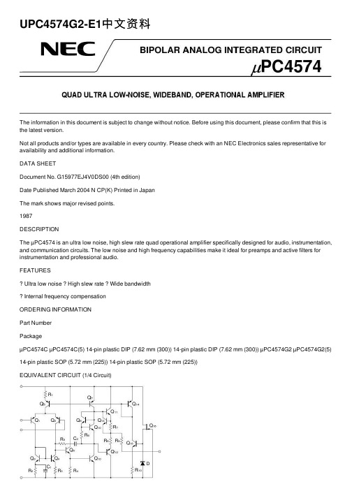
UPC4574G2-E1中⽂资料The information in this document is subject to change without notice. Before using this document, please confirm that this is the latest version.Not all products and/or types are available in every country. Please check with an NEC Electronics sales representative for availability and additional information.DATA SHEETDocument No. G15977EJ4V0DS00 (4th edition)Date Published March 2004 N CP(K) Printed in JapanThe mark shows major revised points.1987DESCRIPTIONThe µPC4574 is an ultra low noise, high slew rate quad operational amplifier specifically designed for audio, instrumentation, and communication circuits. The low noise and high frequency capabilities make it ideal for preamps and active filters for instrumentation and professional audio.FEATURESUltra low noise High slew rate Wide bandwidthInternal frequency compensationORDERING INFORMATIONPart NumberPackageµPC4574C µPC4574C(5) 14-pin plastic DIP (7.62 mm (300)) 14-pin plastic DIP (7.62 mm (300)) µPC4574G2 µPC4574G2(5) 14-pin plastic SOP (5.72 mm (225)) 14-pin plastic SOP (5.72 mm (225))EQUIVALENT CIRCUIT (1/4 Circuit)I I I NVVPIN CONFIGURATION (Top View)OUT 4I I4I N4V ?I N3I I3OUT 3OUT 1I I1I N1V +I N2I I2OUT 2PC4574C, 4574C(5), 4574G2, 4574G2(5)µData Sheet G15977EJ4V0DS2ABSOLUTE MAXIMUM RATINGS (T A = 25°C)Parameter SymbolRatings Unit Voltage between V +and V ? Note1V +V0.3 to +36VDifferential Input Voltage V ID ±30 V Input VoltageNote2V IV ??0.3 to V ++0.3 V Output VoltageNote3V OV ??0.3 to V + +0.3VC Package Note4570 mW Power Dissipation G2 PackageNote5P T 550 mW Output Short Circuit DurationNote610 sec Operating Ambient Temperature T A ?20 to +80 °C Storage TemperatureT stg55 to +125°CNotes 1. Reverse connection of supply voltage can cause destruction.2. The input voltage should be allowed to input without damage or destruction. Even during the transition periodof supply voltage, power on/off etc., this specification should be kept. The normal operation will establish when the both inputs are within the Common Mode Input Voltage Range of electrical characteristics.3. This specification is the voltage which should be allowed to supply to the output terminal from externalwithout damage or destructive. Even during the transition period of supply voltage, power on/off etc., this specification should be kept. The output voltage of normal operation will be the Output Voltage Swing of electrical characteristics.4. Thermal derating factor is –7.6 mW/°C when ambient temperature is higher than 50°C.5. Thermal derating factor is –5.5 mW/°C when ambient temperature is higher than 25°C.6. Pay careful attention to the total power dissipation not to exceed the absolute maximum ratings, Note 4 andNote 5.RECOMMENDED OPERATING CONDITIONSParameter Symbol MIN. TYP. MAX. UnitSupply Voltage V ± ±4 ±16 V Output Current I O±10 mASource Resistance R S 50k ?Capacitive Load (A V = +1)C L 100 pFµPC4574C, µPC4574G2±Notes 7. Input bias currents flow out from IC. Because each currents are base current of PNP-transistor on input stage.8.This current flows irrespective of the existence of use.Data Sheet G15977EJ4V0DS 3µPC4574C(5), µPC4574G2(5)±Notes 7. Input bias currents flow out from IC. Because each currents are base current of PNP-transistor on input stage.8.This current flows irrespective of the existence of use.4Data Sheet G15977EJ4V0DSMEASUREMENT CIRCUITFig.1 Total Harmonic Distortion Measurement CircuitnFig.3 Flat Noise Measurement Circuit (FLAT+JIS A)V O = 40 dB x V n100 V n =V O40 dBData Sheet G15977EJ4V0DS 5Data Sheet G15977EJ4V0DS6TYPICAL PERFORMANCE CHARACTERISTICS (T A = 25°C, TYP.) T A - Operating Ambient Temperature - ?CPOWER DISSIPATIONP T - T o t a l P o w e r D i s s i p a t i o n - m W800600400200020*********20406080100120110010 k 1 M 1 k 10100 k 10 Mf - Frequency - HzOPEN LOOP FREQUENCY RESPONSEA V - O p e n L o o p V o l t a g e G a i n - d BV ± = ±15 V202040608021.510.50?0.5?1?1.5?2T A - Operating Ambient Temperature - ?CINPUT OFFSET VOLTAGEV I O - I n p u t O f f s e t V o l t a g e - m V= ±15 VV ±each 5 samples data806040200?20550530510490470450T A - Operating Ambient Temperature - ?CINPUT BIAS CURRENTI B - I n p u t B i a s C u r r e n t - n A= ±15 VV ±f - Frequency - HzLARGE SIGNAL FREQUENCY RESPONSE V o m - O u t p u t V o l t a g e S w i n g - V p -p 01020301001 k 10 k 100 k 1 M 10 MV = ±15 V±R L = 10 k ?I O - Output Current - mAOUTPUT CURRENT LIMITV O - O u t p u t V o l t a g e - V±±5±10±15T A - Operating Ambient Temperature - ?CSUPPLY CURRENTI C C - S u p p l y C u r r e n t - m A12963204020060800V = ±15 V±SUPPLY CURRENTI C C - S u p p l y C u r r e n t - m A12963±10±20V - Supply Voltage - V±Data Sheet G15977EJ4V0DS7COMMON MODE INPUT VOLTAGE RANGE V I C M - C o m m o n M o d e I n p u t V o l t a g e R a n g e - V 20100±10±20V - Supply Voltage - V±VOLTAGE FOLLOWER PULSE RESPONSE V O - O u t p u t V o l t a g e - V10551002468t - Time - sµV = ±15 V ±A V = 1R L = 2 k ?INPUT NOISE VOLTAGE (FLAT + JIS A)V n - I n p u t N o i s e V o l t a g e - V r .m .s .1001010.1101001 k10 k100 kR S - Source Resistance - ?V = ±15 V±µf - Frequency - HzINPUT EQUIVALENT NOISE VOLTAGE DENSITY e n - I n p u t E q u i v a l e n t N o i s e V o l t a g e D e n s i t y - n V / H z20468100 1 k10 k 100 k10±R S = 100 VTOTAL HARMONIC DISTORTIONT H D - T o t a l H a r m o n i c D i s t o r t i o n - %10.0010.010.10.000110100 1 k10 k 100 kf - Frequency - HzV = ±15 V ±V O = 3 V r.m.s.A V = 1R L = 2 k ?Data Sheet G15977EJ4V0DS8PACKAGE DRAWINGS (Unit: mm)14-PIN PLASTIC DIP (7.62 mm (300))ITEM MILLIMETERS A 19.22±0.22.14 MAX.F I J D 1.32±0.12G 3.6±0.3C B 2.54 (T.P.)0.50±0.10R 0~15°H 0.51 MIN.K 7.62 (T.P.)L 6.4±0.23.554.3±0.2N 0.25NOTES1. Each lead centerline is located within 0.25 mm ofits true position (T.P.) at maximum material condition.2. ltem "K" to center of leads when formed parallel.P14C-100-300B1-3M 0.25+0.10?0.05Data Sheet G15977EJ4V0DS9ITEM B C I 14-PIN PLASTIC SOP (5.72 mm (225))D E G H J PMILLIMETERS 1.27 (T.P.)1.42 MAX.A 10.2±0.264.4±0.10.1±0.10.426.5±0.21.49+0.08?0.071.1±0.163°+7°?3°NOTEEach lead centerline is located within 0.1 mm ofits true position (T.P.) at maximum material condition.F 1.59+0.21?0.2K L M N 0.6±0.20.170.10.10+0.08?0.07S14GM-50-225B, C-6RECOMMENDED SOLDERING CONDITIONSThe µPC4574 should be soldered and mounted under the following recommended conditions.For soldering methods and conditions other than those recommended below, contact an NEC Electronics sales representative.For technical information, see the following website.Semiconductor Device Mount Manual (/doc/015a7dda76a20029bd642de6.html/pkg/en/mount/index.html)Type of Surface Mount DeviceµPC4574G2, 4574G2(5): 14-pin plastic SOP (5.72 mm (225))Process ConditionsSymbol Infrared Ray Reflow Peak temperature: 230°C or below (Package surface temperature),Reflow time: 30 seconds or less (at 210°C or higher),Maximum number of reflow processes: 1 time.IR30-00-1Vapor Phase Soldering Peak temperature: 215°C or below (Package surface temperature),Reflow time: 40 seconds or less (at 200°C or higher),Maximum number of reflow processes: 1 time.VP15-00-1Wave Soldering Solder temperature: 260°C or below, Flow time: 10 seconds or less,Maximum number of flow processes: 1 time,Pre-heating temperature: 120°C or below (Package surface temperature).WS60-00-1Partial Heating Method Pin temperature: 300°C or below,Heat time: 3 seconds or less (Per each side of the device).–Caution Apply only one kind of soldering condition to a device, except for "partial heating method", or thedevice will be damaged by heat stress.Type of Through-hole DeviceµPC4574C, 4574C(5): 14-pin plastic DIP (7.62 mm (300))Process ConditionsWave Soldering (only to leads) Solder temperature: 260°C or below, Flow time: 10 seconds or less.Partial Heating Method Pin temperature: 300°C or below,Heat time: 3 seconds or less (per each lead).Caution For through-hole device, the wave soldering process must be applied only to leads, and make sure that the package body does not get jet soldered.Data Sheet G15977EJ4V0DS10The information in this document is current as of March, 2004. The information is subject to change without notice. For actual design-in, refer to the latest publications of NEC Electronics data sheets or data books, etc., for the most up-to-date specifications of N EC Electronics products. N ot all products and/or types are available in every country. Please check with an N EC Electronics sales representative for availability and additional information.No part of this document may be copied or reproduced in any form or by any means without the prior written consent of NEC Electronics. NEC Electronics assumes no responsibility for any errors that may appear in this document.NEC Electronics does not assume any liability for infringement of patents, copyrights or other intellectual property rights of third parties by or arising from the use of NEC Electronics products listed in this document or any other liability arising from the use of such products. No license, express, implied or otherwise, is granted under any patents, copyrights or other intellectual property rights of NEC Electronics or others.Descriptions of circuits, software and other related information in this document are provided for illustrative purposes in semiconductor product operation and application examples. The incorporation of these circuits, software and information in the design of a customer's equipment shall be done under the full responsibility of the customer. NEC Electronics assumes no responsibility for any losses incurred by customers or third parties arising from the use of these circuits, software and information.While NEC Electronics endeavors to enhance the quality, reliability and safety of NEC Electronics products, customers agree and acknowledge that the possibility of defects thereof cannot be eliminated entirely. To minimize risks of damage to property or injury (including death) to persons arising from defects in NEC Electronics products, customers must incorporate sufficient safety measures in their design, such as redundancy, fire-containment and anti-failure features.NEC Electronics products are classified into the following three quality grades: "Standard", "Special" and "Specific".The "Specific" quality grade applies only to NEC Electronics products developed based on a customer-designated "quality assurance program" for a specific application. The recommended applications of an NEC Electronics product depend on its quality grade, as indicated below. Customers must check the quality grade of each NEC Electronics product before using it in a particular application."Standard":Computers, office equipment, communications equipment, test and measurement equipment, audioand visual equipment, home electronic appliances, machine tools, personal electronic equipment and industrial robots. "Special":Transportation equipment (automobiles, trains, ships, etc.), traffic control systems, anti-disastersystems, anti-crime systems, safety equipment and medical equipment (not specifically designed for life support). "Specific":Aircraft, aerospace equipment, submersible repeaters, nuclear reactor control systems, lifesupport systems and medical equipment for life support, etc.The quality grade of NEC Electronics products is "Standard" unless otherwise expressly specified in NEC Electronics data sheets or data books, etc. If customers wish to use NEC Electronics products in applications not intended by NEC Electronics, they must contact an NEC Electronics sales representative in advance to determine NEC Electronics' willingness to support a given application.(Note)(1)"NEC Electronics" as used in this statement means NEC Electronics Corporation and also includes itsmajority-owned subsidiaries.(2)"NEC Electronics products" means any product developed or manufactured by or for NEC Electronics (asdefined above).M8E 02. 11-1。
- 1、下载文档前请自行甄别文档内容的完整性,平台不提供额外的编辑、内容补充、找答案等附加服务。
- 2、"仅部分预览"的文档,不可在线预览部分如存在完整性等问题,可反馈申请退款(可完整预览的文档不适用该条件!)。
- 3、如文档侵犯您的权益,请联系客服反馈,我们会尽快为您处理(人工客服工作时间:9:00-18:30)。
POWER AND GROUND(VEGA-N)VEGA BOARDDESIGNATOR PART TYPE GNDV1_0H V1_8H U1VEGA_V5_JLWB8F6B7U10V2V6V10U2FLASH_FBGA48_JLW H1H6Y1XTALSMD_JLW24N17L11L8L7K12K11K8H9M8G17K13J7M12J9N6J12N13K1T13K7L10K9J10N7POWER AND GROUND LIST -1B13F7B12F1F11P17G7F13B17F8C16C1F9E1C14F10H17G11J13H1L6J8M13H12M11H10M9H7M6H2L13H8M7END POWER AND GROUND LISTV4U12V3V8V12U15U4U2U1T2T1R2L12L9K10J11N8H11M10G12K6F2F12G8G13G10J6G9H13DABCTITLE..AD B C7XTAL_ZXXTAL_ZX -@worklib_lib.DESIGN3D5WDOUT WDOUT -@worklib_lib.DESIGN 2B4TRSTN TRSTN -@worklib_lib.DESIGN 3C53C8TDO TDO -@worklib_lib.DESIGN 3C53C8SW10SW10-@worklib_lib.DESIGN 4D3SERIAL_SOUT SERIAL_SOUT -@worklib_lib.DESIGN 3B53B83B83C8SERIAL_SIN SERIAL_SIN-@worklib_lib.DESIGN3B53B83B83C8SATA_TX_N SATA_TX_N -@worklib_lib.DESIGN 2D4SATA_TP_N SATA_TP_N -@worklib_lib.DESIGN 2D3SATA_RX_P SATA_RX_P -@worklib_lib.DESIGN 2C4SATA_RX_N SATA_RX_N -@worklib_lib.DESIGN 2C4SATA_RP_P SATA_RP_P -@worklib_lib.DESIGN 2C3SATA_RP_N SATA_RP_N -@worklib_lib.DESIGN 2C3SATA_PIN_11SATA_PIN_11-@worklib_lib.DESIGN 2B22C7SATA_0_VTERM SATA_0_VTERM -@worklib_lib.DESIGN 4B5SATA_0_VDD SATA_0_VDD -@worklib_lib.DESIGN 4B5SATA_0_VCOVDD SATA_0_VCOVDD -@worklib_lib.DESIGN 4A5SAS_VDDSAS_VDD -@worklib_lib.DESIGN4A7SAS_TS_P SAS_TS_P-@worklib_lib.DESIGN2C7SAS_TS_N SAS_TS_N -@worklib_lib.DESIGN 2C7SAS_TP_P SAS_TP_P -@worklib_lib.DESIGN 2D7SAS_TP_N SAS_TP_N -@worklib_lib.DESIGN 2D7SAS_RS_P SAS_RS_P -@worklib_lib.DESIGN 2C7SAS_RS_N SAS_RS_N -@worklib_lib.DESIGN 2C7SAS_RP_P SAS_RP_P -@worklib_lib.DESIGN 2D7SAS_RP_N SAS_RP_N -@worklib_lib.DESIGN 2D7SAS_1_VTERM SAS_1_VTERM -@worklib_lib.DESIGN 4A7SAS_0_VTERM SAS_0_VTERM -@worklib_lib.DESIGN 4A7SAS1_TX_P SAS1_TX_P -@worklib_lib.DESIGN 2D5SAS1_TX_N SAS1_TX_N -@worklib_lib.DESIGN 2D5SAS1_RX_P SAS1_RX_P -@worklib_lib.DESIGN 2D5SAS1_RX_NSAS1_RX_N -@worklib_lib.DESIGN 2D5SAS0_TX_P SAS0_TX_P -@worklib_lib.DESIGN 2C5SAS0_TX_N SAS0_TX_N -@worklib_lib.DESIGN 2C5SAS0_RX_P SAS0_RX_P -@worklib_lib.DESIGN 2C5SAS0_RX_N SAS0_RX_N -@worklib_lib.DESIGN 2C5RTRIM_AN RTRIM_AN -@worklib_lib.DESIGN 2C5RTRIM_A RTRIM_A -@worklib_lib.DESIGN 2C5RST_OUT_N RST_OUT_N -@worklib_lib.DESIGN 2B4REV2REV2-@worklib_lib.DESIGN2C4REV1REV1-@worklib_lib.DESIGN 2C4REV0REV0-@worklib_lib.DESIGN2B4REFCLK_P REFCLK_P -@worklib_lib.DESIGN 3D5REFCLK_OUT REFCLK_OUT -@worklib_lib.DESIGN 3D5REFCLK_N REFCLK_N -@worklib_lib.DESIGN 3D5READY_LED_N READY_LED_N -@worklib_lib.DESIGN 2C62C2PROCMONPROCMON -@worklib_lib.DESIGN3C5POWER_DOWN POWER_DOWN -@worklib_lib.DESIGN 4D4PLL_VDDA18PLL_VDDA18-@worklib_lib.DESIGN 4B7PLL_SSC_VDDA PLL_SSC_VDDA -@worklib_lib.DESIGN 4C5PLL_SSC_VDD PLL_SSC_VDD -@worklib_lib.DESIGN 4B7@worklib_lib.DESIGNPLL_LOCK_STATUS PLL_LOCK_STATUS -2B4MFG_MODEMFG_MODE -@worklib_lib.DESIGN 2B43C7LSI_TNLSI_TN -@worklib_lib.DESIGN 3C5INSTR_CE_N INSTR_CE_N -@worklib_lib.DESIGN 3D4IDDTIDDT -@worklib_lib.DESIGN 3C5I2C_SDA I2C_SDA -@worklib_lib.DESIGN 3C53C8I2C_SCL I2C_SCL -@worklib_lib.DESIGN 3C53C8I2C_INT_L I2C_INT_L -@worklib_lib.DESIGN 3C5GPIO_MDIO GPIO_MDIO -@worklib_lib.DESIGN 2C43C7GPIO_MDC GPIO_MDC -@worklib_lib.DESIGN 2C43C7GPIO_26GPIO_26-@worklib_lib.DESIGN 2B4GPIO_15GPIO_15-@worklib_lib.DESIGN 2B5GPIO_14GPIO_14-@worklib_lib.DESIGN 2B5GPIO_12GPIO_12-@worklib_lib.DESIGN 2B5GPIO_11GPIO_11-@worklib_lib.DESIGN 2B5GPIO_10GPIO_10-@worklib_lib.DESIGN 2B5GPIO_9GPIO_9-@worklib_lib.DESIGN 2B5GPIO_8GPIO_8-@worklib_lib.DESIGN2B5GPIO_7GPIO_7-@worklib_lib.DESIGN 2B5GPIO_6GPIO_6-@worklib_lib.DESIGN 2B5GPIO_5GPIO_5-@worklib_lib.DESIGN 2B5GPIO_4GPIO_4-@worklib_lib.DESIGN 2B5GPIO_3GPIO_3-@worklib_lib.DESIGN 2B5GPIO_2GPIO_2-@worklib_lib.DESIGN 2C5GPIO_0GPIO_0-@worklib_lib.DESIGN 2C5GLBL_RST_N GLBL_RST_N -@worklib_lib.DESIGN 3B53C74B2FW_POWER_DOWN FW_POWER_DOWN -@worklib_lib.DESIGN 2B64C5FL_WP_NFL_WP_N -@worklib_lib.DESIGN3B13C5FL_WE_N FL_WE_N -@worklib_lib.DESIGN 3D4FL_RY FL_RY -@worklib_lib.DESIGN 3B1FL_RST_NFL_RST_N-@worklib_lib.DESIGN3D4FL_OE_N FL_OE_N -@worklib_lib.DESIGN 3D4FL_D7FL_D7-@worklib_lib.DESIGN 3B43C1FL_D6FL_D6-@worklib_lib.DESIGN 3B43C1FL_D5FL_D5-@worklib_lib.DESIGN 3B43C1FL_D4FL_D4-@worklib_lib.DESIGN 3B43C1FL_D3FL_D3-@worklib_lib.DESIGN 3B43C1FL_D2FL_D2-@worklib_lib.DESIGN 3B43C1FL_D1FL_D1-@worklib_lib.DESIGN 3B43C1FL_D0FL_D0-@worklib_lib.DESIGN 3B43C1FL_CE_N FL_CE_N -@worklib_lib.DESIGN 3D4FL_BYTE_N FL_BYTE_N -@worklib_lib.DESIGN 3B3FL_A21FL_A21-@worklib_lib.DESIGN3C4FL_A17FL_A17-@worklib_lib.DESIGN 3C4FL_A15FL_A15-@worklib_lib.DESIGN 3C45C3FL_A13FL_A13-@worklib_lib.DESIGN 3C45A6FL_A10FL_A10-@worklib_lib.DESIGN 3C4FL_A9FL_A9-@worklib_lib.DESIGN 3C4FL_A8FL_A8-@worklib_lib.DESIGN 3C4FL_A6FL_A6-@worklib_lib.DESIGN3C4FL_A0FL_A0-@worklib_lib.DESIGN 3D4FLT_LED FLT_LED -@worklib_lib.DESIGN 2C4FC1_VCO_VDD FC1_VCO_VDD -@worklib_lib.DESIGN 4B7FC0_VCO_VDD FC0_VCO_VDD -@worklib_lib.DESIGN 4B7EXT_ARMCLK EXT_ARMCLK -@worklib_lib.DESIGN 2B4DRIVE_PWR_SW DRIVE_PWR_SW -@worklib_lib.DESIGN 2C4DIODE_CDIODE_C -@worklib_lib.DESIGN3C5DIODE_ADIODE_A -@worklib_lib.DESIGN 3C5CS_TAP CS_TAP -@worklib_lib.DESIGN 3C5ACT_LED ACT_LED -@worklib_lib.DESIGN 2C4BaseSignalSynonyms Location([Zone][dir])Base nets and synonymsfor worklib_lib.DESIGN(@worklib_lib.design(sch_1))Date:Mar 2213:37:282010Design:design Title:Basenet Report FL_A11FL_A11-@worklib_lib.DESIGN 3C45B6FL_A14FL_A14-@worklib_lib.DESIGN 3C45A6FL_A16FL_A16-@worklib_lib.DESIGN 3C45C3FL_A18FL_A18-@worklib_lib.DESIGN 3C4FL_A19FL_A19-@worklib_lib.DESIGN 3C4FL_A20FL_A20-@worklib_lib.DESIGN3C4TDI TDI -@worklib_lib.DESIGN 3C53C8V1_0A V1_0A -@worklib_lib.DESIGN 4A84B44C14C5VDD_DIODE VDD_DIODE -@worklib_lib.DESIGN 4C7XTAL_A XTAL_A -@worklib_lib.DESIGN 3D5VDDA18VDDA18-@worklib_lib.DESIGN4C7TMS TMS -@worklib_lib.DESIGN3C53C8TCK TCK -@worklib_lib.DESIGN 3C53C8SATA_TX_P SATA_TX_P -@worklib_lib.DESIGN 2D4SATA_TP_P SATA_TP_P -@worklib_lib.DESIGN 2D3FL_A12FL_A12-@worklib_lib.DESIGN 3C45A6FL_A7FL_A7-@worklib_lib.DESIGN 3C4FL_A5FL_A5-@worklib_lib.DESIGN 3C4FL_A4FL_A4-@worklib_lib.DESIGN 3C4FL_A3FL_A3-@worklib_lib.DESIGN 3C45B6FL_A2FL_A2-@worklib_lib.DESIGN 3C4FL_A1FL_A1-@worklib_lib.DESIGN 3C4DABCTITLE..ADBCTN116TESTNODE design[4B7]8TN120TESTNODEdesign[4D7]TN118TESTNODE design[4A7]TN109TESTNODE design[3C4]TN106TESTNODE design[3C4]TN105TESTNODE design[3C4]TN101TESTNODE design[3C4]TN98TESTNODE design[3C4]TN96TESTNODE design[3C4]TN93TESTNODE design[3C4]TN92TESTNODE design[3C4]TN91TESTNODE design[3C4]TN90TESTNODE design[3D4]TN89TESTNODE design[3D4]TN88TESTNODE design[3D4]TN87TESTNODE design[3D4]TN86TESTNODE design[3D4]TN85TESTNODE design[3D4]TN84TESTNODE design[3D4]TN83TESTNODE design[3D6]TN82TESTNODE design[2C2]TN81TESTNODE design[2C3]TN80TESTNODE design[2B3]TN79TESTNODE design[2C3]TN78TESTNODE design[2C3]TN77TESTNODE design[2C3]TN76TESTNODE design[2C6]TN75TESTNODE design[2C6]TN74TESTNODE design[2C6]TN66TESTNODE design[4D5]TN65TESTNODE design[4C4]TN64TESTNODE design[3B1]TN63TESTNODE design[3B1]TN62TESTNODE design[3B3]TN61TESTNODE design[3B4]TN60TESTNODE design[3B4]TN59TESTNODE design[3B4]TN58TESTNODE design[3B4]TN57TESTNODE design[3B4]TN56TESTNODE design[3B4]TN55TESTNODE design[3B4]TN54TESTNODE design[3B4]TN53TESTNODE design[3C6]TN52TESTNODE design[3C6]TN51TESTNODE design[3D6]TN50TESTNODE design[3D6]TN49TESTNODE design[3C6]TN48TESTNODE design[3C6]TN47TESTNODE design[3D6]TN46TESTNODE design[2C3]TN45TESTNODE design[2B3]TN44TESTNODE design[2B3]TN43TESTNODE design[2B3]TN42TESTNODE design[2C3]TN41TESTNODE design[2B3]TN40TESTNODE design[2C3]TN39TESTNODE design[2B3]TN38TESTNODE design[2B3]TN37TESTNODE design[2C3]TN36TESTNODE design[2B6]TN35TESTNODE design[2B6]TN34TESTNODE design[2B6]TN33TESTNODE design[2B6]TN32TESTNODE design[2B6]TN31TESTNODE design[2B6]TN30TESTNODE design[2B6]TN29TESTNODE design[2B6]TN28TESTNODE design[2B6]TN27TESTNODE design[2B6]TN26TESTNODE design[2B6]TN25TESTNODE design[2B6]TN24TESTNODE design[3C6]TN23TESTNODE design[3C6]TN22TESTNODEdesign[3C6]TN21TESTNODE design[3B7]TN20TESTNODE design[3B6]TN19TESTNODE design[3C6]TN18TESTNODE design[3C6]TN17TESTNODE design[3C6]TN16TESTNODE design[2B6]TN15TESTNODE design[3C6]TN14TESTNODE design[3C6]TN13TESTNODE design[3C6]TN12TESTNODE design[2C6]TN11TESTNODE design[2C6]TN10TESTNODE design[3C1]TN9TESTNODE design[3C1]TN8TESTNODE design[3C1]TN7TESTNODE design[3C1]TN6TESTNODE design[3C1]TN5TESTNODE design[3C1]TN4TESTNODE design[3C1]TN3TESTNODE design[3C6]TN2TESTNODE design[3C6]TN1TESTNODE design[3C6]R97RESdesign[5A5]R79RES design[5B5]R76RES design[5B5]R69RES_JLW design[5C3]R68RESdesign[5A5]R67RES design[5A5]R63RES_JLW design[4C1]R62RES_JLW design[4B1]R57RESdesign[4B3]R40RES_JLW design[4D5]R37RES design[3B3]R31RESdesign[4C3]R29RES_JLW design[4B3]R26RES design[3C6]R20RES_JLW design[4C3]R19RESdesign[2C3]R18RES design[2C3]R17RES design[2B3]R15RES_JLW design[4C2]R14RES design[4C3]R13RES design[4D3]R12RES design[4D3]R10RES design[4D4]R9RES design[5C3]R6RES_JLW design[3C7]R5RES_JLW design[3C7]R4RESdesign[3C5]R3RES design[3D6]R2RES design[3C6]R1RES design[3D6]Q7NPN_3design[2C2]Q5PNP_3design[4B3]Q3NPN_DUAL design[4D54B3]L30FERRBEAD_JLW design[4B5]L25FERRBEAD_JLW design[4C8]L22FERRBEAD_JLW design[4A8]L19FERRBEAD_JLW design[4B8]L18FERRBEAD_JLW design[4C8]L17FERRBEAD_JLW design[3D6]L16FERRBEAD_JLW design[4A8]L15FERRBEAD_JLW design[4B5]L14FERRBEAD_JLW design[4B5]L13FERRBEAD_JLW design[4A5]L12FERRBEAD_JLW design[4A8]L11FERRBEAD_JLW design[4C5]L10FERRBEAD_JLW design[4B8]L9FERRBEAD_JLW design[4B8]L8FERRBEAD_JLW design[4B8]L7FERRBEAD_JLW design[4A8]L4IND_JLWdesign[4C1]L3IND_JLW design[4B2]L2A IND_JLW design[4D3]L2IND_JLW design[4D3]L1A IND_JLW design[4C3]L1IND_JLW design[4C3]J4SFV20R_JLWdesign[3C8]J3A MOLEX_527930470design[3B8]J3HFW4R_KAdesign[3B8]J2CONN_SATA_JLW design[2C1]J1CONN_SAS_JLW_1design[2C7]CR1DIODE_KAdesign[4C4]C94CAP_JLW design[4D7]C93CAPdesign[4A7]C80CAP_JLWdesign[3B5]C79CAP_JLW design[4D1]C78CAP_JLW design[4D1]C77CAPdesign[4C2]C76CAP_JLW design[4C2]C75CAP_JLW design[4C1]C74CAP design[4D1]C73CAP design[4D2]C72CAP design[4D2]C71CAP_JLW design[4C2]C70CAPdesign[4C1]C69CAP_JLW design[4D2]C68CAPdesign[4C1]C67CAP_JLW design[4C2]C66CAP_JLW design[4B1]C65CAP_JLW design[4D2]C64CAPdesign[4C1]C63CAP_JLW design[4C2]C62CAPdesign[4C1]C61CAP design[4D1]C60CAP_JLW design[4D3]C59CAPdesign[4C2]C58CAP design[4B2]C57CAP_JLW design[4D2]C56CAP_JLW design[4C3]C55CAP_JLW design[4C2]C54CAP design[4B2]C53CAP design[4C2]C52CAP_JLW design[4C3]C51CAPdesign[4C2]C50CAP_JLW design[4D2]C49CAPdesign[4C3]C48CAP_JLW design[4C2]C47CAP_JLW design[4D4]C46CAP_JLW design[4C4]C45CAP_JLW design[4D4]C43CAPdesign[4A5]C34CAP_JLW design[4B4]C32CAP design[4B5]C28CAP design[4B7]C27CAP design[4C7]C26CAP_JLW design[4B4]C25CAP design[4A7]C23CAP design[4C7]C21CAP design[4A7]C20CAP_JLW design[3D1]C18CAP_JLW design[4B5]C17CAPdesign[3D7]C16CAP_JLW design[4C5]C15CAP_JLW design[4C5]C13CAP_JLW design[3D6]C12CAP_JLW design[2C3]C11CAP_JLW design[2C3]C10CAP_JLW design[2D3]C8CAP_JLW design[2D6]C7CAP_JLW design[2D6]C6CAP_JLW design[2D6]C5CAP_JLW design[2D6]C3CAP_JLW design[2C6]C2CAP_JLW design[2C6]C1CAP_JLW design[2C6]Date:Mar 2213:37:282010Design:designTitle:Cref Part Report C4CAP_JLW design[2C6]C9CAP_JLW design[2D3]C14CAPdesign[3D6]C19CAP_JLW design[4C5]C24CAP design[4B7]R11RES design[4C4]R16RES design[2C6]R21RESdesign[4D3]R22RES_JLW design[4D3]R24RES design[2C6]R25RES design[2C2]R28RES design[4B4]R30RES design[2B2]R36RES design[3C6]R39RESdesign[3B1]TN95TESTNODE design[3C4]TN99TESTNODE design[3C4]TN103TESTNODE design[3C4]TN117TESTNODE design[4A7]TN119TESTNODE design[4A7]TN113TESTNODE design[4C7]TN114TESTNODE design[4B7]TN115TESTNODE design[4B7]TN112TESTNODE design[4C7]TN111TESTNODE design[4A8]TN110TESTNODE design[3C4]TN108TESTNODE design[3C4]TN107TESTNODE design[3C4]TN104TESTNODE design[3C4]TN102TESTNODE design[3C4]TN100TESTNODE design[3C4]TN97TESTNODE design[3C4]TN94TESTNODE design[3C4]R41RES_JLW design[4D5]R38RES design[3B1]R34RES_JLW design[3D6]R27RES design[2C3]C44CAP_JLW design[4D4]C42CAP design[4A5]C37CAP design[4C5]C41CAP design[4B3]C40CAP_JLW design[4D4]C39CAPdesign[4A7]C38CAP design[4A7]C36CAP design[4A5]C35CAP_JLW design[3D6]C33CAPdesign[4B5]C29CAP design[4B7]C22CAP design[4A7]DABCTITLE..ADBCTN121TESTNODE design[4D7]TN122TESTNODE design[4D7]TN123TESTNODE design[4D7]TN124TESTNODE design[4D7]TN125TESTNODE design[4D7]TN126TESTNODE design[4D7]TN127TESTNODE design[4C7]TN128TESTNODE design[4C7]TN129TESTNODE design[4C7]TN130TESTNODE design[4C5]TN131TESTNODE design[4B5]TN132TESTNODE design[4A5]TN133TESTNODE design[4A5]TN134TESTNODE design[4B4]TN716TESTNODE design[4C1]U1VEGA_V6_JLW design[3C5]U1VEGA_V6_JLWdesign[4B6]U3MP2120_JLW design[4D4]Y1XTALSMD_JLWdesign[3D7]9U4MP2119_JLW design[4C3]U2FLASH_FBGA48_JLW design[3C2]U1VEGA_V6_JLW design[2C5]TN715TESTNODEdesign[4C1]TN714TESTNODE design[4C1]TN713TESTNODE design[4D1]TN712TESTNODE design[4D1]TN711TESTNODE design[4D1]TN159TESTNODE design[4B5]TN158TESTNODE design[2C2]TN157TESTNODE design[4B3]TN156TESTNODE design[4C3]TN155TESTNODE design[4B3]TN154TESTNODE design[4C4]TN153TESTNODE design[4B4]TN152TESTNODE design[2C2]TN151TESTNODE design[4D3]TN150TESTNODE design[4C3]TN149TESTNODE design[4D3]TN148TESTNODE design[4C3]TN147TESTNODE design[4D3]TN146TESTNODE design[4D5]TN145TESTNODE design[4D1]TN144TESTNODE design[4C1]TN143TESTNODE design[4C1]TN142TESTNODE design[4B1]TN141TESTNODE design[4D3]TN140TESTNODE design[4C3]TN139TESTNODE design[4D3]TN137TESTNODE design[4C4]TN136TESTNODE design[4C3]TN135TESTNODE design[4C4]DABCTITLE..ADB C。