PDB1511221MZF中文资料
DA221中文资料

DA221中文资料Diodes1/4Switching diodeDA221M / DA221 / DA204U / DA204K DA228U / DA228K /UMR12Nz Applications Bias circuitsProtection circuitsz Features1) Three types of packages are available. (VMD3, EMD3, UMD3, SMD3)2) Two diode elements are connected in series (V F × 2) per circuit.z ConstructionSilicon epitaxial planarz Circuitz External dimensions (Unit : mm)Diodes2/4z MarkingUMD3DA204UDA228U UMD6UMR12NR12SMD3DA204KDA228KK BUKBU EMD3DA221KVMD3DA221Mz Absolute maximum ratings (T a=25°C)Type V RM (V)V R (V)I FM (mA)I O (mA)I surge (mA)(1μs)(TOTAL)Pd(mW)Tj(°C)Tstg(°C)DA2212020200100300150150?55 to +150DA221M 2020200100300150150?55 to +150DA204U 2020200100300200150?55 to +150DA228K 8080200100300200150?55 to +150UMR12N808020010030020015055 to +15055 to +150DA228U 8080200100300200150?55 to +150DA204K 2020200100300200150Peak reverse voltage Peak forward current Mean rectifying current Surge current Power dissipation Junction temperatureStoragetemperature DC reverse voltagez Electrical characteristics (T a=25°C)TypeForward voltageV F (V)Max.I R (μA)Max.Reverse current Fig.Cond.Cond.I F (mA)V R (V)DA221 1.0100.115 1 to 4DA221M 1.0100.115 1 to 45 to 9UMR12N1.210080DA204U 1.0100.115 1 to 40.1DA228U 1.210080 5 to 90.11.01015DA204K 1 to 40.1DA228K 1.210080 5 to 9Diodes3/4z Electrical characteristic curves (T a=25°C) (DA221, DA204U, DA204K) …Fig.1 to 4T a =125°CD1D1+D20.40.8 1.2 1.6 2.0 2.41001011.00.0175°C5°C25°C125°C75°C25°C25°CF O R W A R D C U R R E N T : I F (m A )FORWARD VOLTAGE : V F (V)Fig.1 Forward characteristicsF O R W A R D C U R R E N T : I F (m A )FORWARD VOLTAGE : V F (V)Fig.2 Forward characteristicsD2 125°CD1 100°C D2 100°CD1 75°C D2 75°C51015200.010.1110100D1 Ta=125°CR E V E R S E CU R R E N T : I R (n A )REVERSE VOLTAGE : V R (V)Fig.3 Reverse characteristics12510C A P A C I T A N C E B E T W E E N T E R M I N A L S : C T (p F )REVERSE VOLTAGE : V R (V)Fig.4 Capacitance between terminals characteristicsDiodes4/4(DA228U, DA228K, UMR12N) …Fig.5 to 9F O R W A R D C U R R E N T : I F (m A )FORWARD VOLTAGE : V F (V)Fig.5 Forward characteristics F O R W A R D C U R R E N T : I F(m A )FORWARD VOLTAGE : V F (V)Fig.6 Forward characteristics R E V E R S E C U R R EN T : I R (n A )REVERSE VOLTAGE : V R (V)Fig.7 Reverse characteristicsR E V E R S E C U R RE N T : I R (n A )REVERSE VOLTAGE : V R (V)Fig.8 Reverse characteristics110C A P A C I T A N C E B E T W E E N T E R M I N A L S : C T (p F )REVERSE VOLTAGE : V R (V)Fig.9 Capacitance between terminals characteristicsAppendixAbout Export Control Order in JapanProducts described herein are the objects of controlled goods in Annex 1 (Item 16) of Export Trade ControlOrder in Japan.In case of export from Japan, please confirm if it applies to "objective" criteria or an "informed" (by MITI clause)on the basis of "catch all controls for Non-Proliferation of Weapons of Mass Destruction.Appendix1-Rev1.0。
CSNE151中文资料
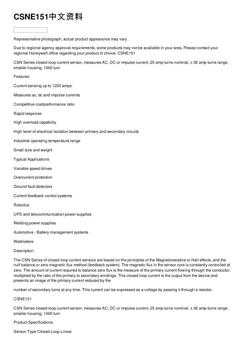
CSNE151中⽂资料Representative photograph, actual product appearance may vary.Due to regional agency approval requirements, some products may not be available in your area. Please contact your regional Honeywell office regarding your product of choice. CSNE151CSN Series closed loop current sensor, measures AC, DC or impulse current, 25 amp-turns nominal, ± 36 amp-turns range, smaller housing, 1000 turnFeaturesCurrent sensing up to 1200 ampsMeasures ac, dc and impulse currentsCompetitive cost/performance ratioRapid responseHigh overload capabilityHigh level of electrical isolation between primary and secondary circuitsIndustrial operating temperature rangeSmall size and weightTypical ApplicationsVariable speed drivesOvercurrent protectionGround fault detectorsCurrent feedback control systemsRoboticsUPS and telecommunication power suppliesWelding power suppliesAutomotive - Battery management systemsWattmetersDescriptionThe CSN Series of closed loop current sensors are based on the principles of the Magnetoresistive or Hall effects, and the null balance or zero magnetic flux method (feedback system). The magnetic flux in the sensor core is constantly controlled at zero. The amount of current required to balance zero flux is the measure of the primary current flowing through the conductor, multiplied by the ratio of the primary to secondary windings. This closed loop current is the output from the device and presents an image of the primary current reduced by thenumber of secondary turns at any time. This current can be expressed as a voltage by passing it through a resistor.CSNE151CSN Series closed loop current sensor, measures AC, DC or impulse current, 25 amp-turns nominal, ± 36 amp-turns range, smaller housing, 1000 turnProduct SpecificationsSensor Type Closed Loop LinearSensed Current Type ac or dcSensed Current Range± 36 APackage Style Series Connect PCB MountOutput Type CurrentMaximum Continuous Current± 36 ASupply Current± 10 mA + outputSupply Voltage± 15.0 VdcOffset Current< ± 0.15 mAOffset Current Drift< ± 0.6 mACoil Resistance @ 70 °C110 OhmResponse Time< 1 µsCoil Turns1000Output Nominal25 mAOperating Temperature Range0 °C to 70 °C [32 °F to 158 °F]Storage Temperature Range-40 °C to 90 °C [-40 °F to 194 °F]Minimum Measuring Resistance100 OhmMaximum Measuring Resistance320 OhmHousing Material Glass-filled PBT (UL94-V0)Mounting PCB on 13 pinsPinout Style 5 pinAccuracy± 0.5 %Availability GlobalComment Standard 25 A sensor with 5 integral primary turns. UNSPSC Code411121UNSPSC Commodity411121 TransducersSeries Name CSN SeriesCSNE151CSN Series closed loop current sensor, measures AC, DC or impulse current, 25 amp-turns nominal, ± 36 amp-turns range, smaller housing, 1000 turnCSNE151CSN Series closed loop current sensor, measures AC, DC or impulse current, 25 amp-turns nominal, ± 36 amp-turns range, smaller housing, 1000 turn PERSONAL INJURYDO NOT USE these products as safety or emergency stop devices, or in any other application where failure of the product could result in personal injury.Failure to comply with these instructions could result in death or serious injury.MISUSE OF DOCUMENTATIONThe information presented in this product sheet (or catalog) is for reference only.DO NOT USE this document as product installation information.Complete installation, operation and maintenance information is provided in the instructions supplied with each product. Failure to comply with these instructions could result in death or serious injury.Copyright Honeywell Inc.1998-2006 All rights reserved.。
PMC150, PMS150 datasheet V005_CN

PMC150/PMS150 系列
8 位 IO 类型单片机
重要声明
应广科技保留权利在任何时候变更或终止产品,建议客户在使用或下单前与应广科技或代理商 联系以取得最新、最正确的产品信息。
应广科技不担保本产品适用于保障生命安全或紧急安全的应用,应广科技不为此类应用产品承 担任何责任。关键应用产品包括,但不仅限于,可能涉及的潜在风险的死亡,人身伤害,火灾或严 重财产损失。
2. 系统概述和方框图 ................................................................................................................................. 7 3. 引脚功能说明 ........................................................................................................................................ 8
4. 器件电气特性 ...................................................................................................................................... 10 4.1 直流交流电气特性 ........................................................................................................................ 10 4.2 绝对最大值 ................................................................................................................................... 11 4.3 IHRC 频率与 VDD 关系曲线图 .................................................................................................... 12 4.4 ILRC 频率与 VDD 关系曲线图..................................................................................................... 12 4.5 IHRC 频率与温度关系曲线图 ...................................................................................................... 13 4.6 工作电流与 VDD、系统时钟 CLK=IHRC/n 曲线图 ....................................................................... 13 4.7 工作电流与 VDD、系统时钟 CLK=ILRC/n 曲线图........................................................................ 14 4.8 最低工作电流与 VDD、系统时钟 CLK=ILRC/n 曲线图 ................................................................ 15 4.9 引脚拉高电阻曲线图..................................................................................................................... 15 4.10 引脚输出驱电流(Ioh)与灌电流(Iol) 曲线图 ................................................................................. 16 4.11 引脚输出输入高电压与低电压(VIH / VIL) 曲线图 ......................................................................... 16
CMDA42CB15D13L中文资料

Americas Europe 147 Central Avenue Robert Bunsen Str. 1 Hackensack, NJ 07601 D-67098 Bad Durkheim (201) 489-8989 +49 (6322) 9567-0 CMDA42xx15D13L SeriesPower LED (1watt) Technical DatasheetCMDA42 Power series is designed for high current operation and high flux output applications. Its thermal management characteristic are better than other LED solutions due to the SMD package design and good thermal emission material.With these design advantages, it enables the Power LED to be applied in various lighting applications and design solution, automotive, architectural lighting, and large size LCD backlight etc.Features• Super high Flux output and high Luminance• Designed for high current operation• Low thermal resistance• SMT solderbility• Lead Free product• RoHS compliantApplication• Mobile phone flash• Automotive interior / exterior lighting• Automotive signal lighting• Automotive forward lighting• General Lighting (Torch)• Architectural lighting• LCD TV / Monitor Backlight• Projector light source• Traffic Signals• Task lighting• Decorative / Pathway lighting• Remote / Solar powered lighting• Household appliances1Dome TypeNotes :1. All dimensions are in millimeters.2. Scale : none3. This drawing without tolerances are for reference only4. Slug of package is connected to anode.2Americas Europe147 Central Avenue Robert Bunsen Str. 1 Hackensack, NJ 07601 D-67098 Bad Durkheim (201) 489-8989 +49 (6322) 9567-0 - 3 -Americas Europe 147 Central Avenue Robert Bunsen Str. 1 Hackensack, NJ 07601 D-67098 Bad Durkheim (201) 489-8989 +49 (6322) 9567-0 *Notes:[1] ФV is the total luminous flux output as measured with an integrating sphere. [2] Zener diode chip included to protect the LED from ESD. [3] R θ is measured with a metal core PCB (25 ºC ≤TJ ≤ 125 ºC).[4] CML maintains a tolerance of ± 10% on flux and power measurements. [5] CCT ± 5% tester tolerance.[6] Color Coordinate Measurement allowance is ± 0.005[7] A tolerance of ± 0.006V on forward voltage measurements1. Pure White1. 00. 80. 60. 40. 20. 0 300400 500 600 700 800 900W a v e le n g th (n m )2. Warm White1. 00. 80. 60. 40. 20. 0 30 04 005 0 06 00 70 0 8 0 0 9 0 0W a v e le n g t h (n m )4Americas Europe147 Central Avenue Robert Bunsen Str. 1 Hackensack, NJ 07601 D-67098 Bad Durkheim(201) 489-8989+49 (6322) 9567-0 3. Blue, Cyan, Green, Amber, Red1. 00. 80. 60. 40. 20. 0 40 05 0060 0 7 0 0W a v e le n g t h (n m )5Americas Europe147 Central Avenue Robert Bunsen Str. 1 Hackensack, NJ 07601 D-67098 Bad Durkheim (201) 489-8989 +49 (6322) 9567-0 1. Relative Light Output vs. Junction Temperature at I F =350mA, T A =25℃16 0 14 0 12 0 10 0 806040200J u n c tio n T e m p e r a tu r e , T [oC ] J16 0 14 0 12 0 10 0 80 6040 20 00 2 0 406080100 1 2 0J u n c tio n T e m p e r a tu r e , T [o C ]J6Americas Europe 147 Central Avenue Robert Bunsen Str. 1 Hackensack, NJ 07601 D-67098 Bad Durkheim(201) 489-8989+49 (6322) 9567-0 1. Forward Voltage vs. Forward Current, T A =25℃40 035 0 30 0 25 0 20 0 15 0 10 0 50 0 0.00 .5 1.0 1 .5 2.0 2 .5 3.0 3 .5 4.0Forw ard Voltage [V]40 035 0 30 0 25 0 20 0 15 0 10 0 500 .0 0 .51 .0 1 .52 .0 2 .53 .0 3 .5Forw ard Voltage [V]7Americas Europe147 Central Avenue Robert Bunsen Str. 1 D-67098 Bad Durkheim +49 (6322) 9567-0 8Americas Europe147 Central Avenue Robert Bunsen Str. 1 Hackensack, NJ 07601 D-67098 Bad Durkheim (201) 489-8989 +49 (6322) 9567-0 1. Pure White, Warm White, Royal Blue, Blue, Cyan, Green (T JMAX = 125 ºC)Ambient Temperature(oC)2. Amber, Red (T JMAX = 100 ºC)400350300250200 150 1005000 20406080100Ambient Temperature(oC)9Americas Europe147 Central Avenue Robert Bunsen Str. 1 Hackensack, NJ 07601 D-67098 Bad Durkheim(201) 489-8989+49 (6322) 9567-0 1. Pure White, Warm White1.00.80.60.40.20.0-100-80-60 -40 -20 0 20 40 60 80 100D i r e c t i o n a l A n g l e [d e g r e e ]2. Royal Blue, Blue, Cyan, Green1.00.80.60.40.20.03. Amber, Red10-100-80-60 -40 -20 0 20 40 60 80 100-100-80-60 -40 -20 0 20 40 60 80 100D i r e c t i o n a l A n g l e [d e g r e e ]D i r e c t i o n a l A n g l e [d e g r e e ]Note :1. All dimensions are in millimeters2. Scale none3. This drawing without tolerances are for reference only 11Americas Europe147 Central Avenue Robert Bunsen Str. 1(201) 489-8989 +49 (6322) 9567-0 Note :1. The number of loaded products in the reel is 750ea2. All dimensions are in millimeters3. Scale none4. This drawing without tolerances are for reference only12Americas Europe147 Central Avenue Robert Bunsen Str. 1Hackensack, NJ 07601 D-67098 Bad Durkheim(201) 489-8989+49 (6322) 9567-0 1. Reflow Soldering Conditions / ProfilePreliminary heating to be at 180℃max. for 2 minutes max. Soldering heat to be at 260℃max. for 5 seconds max.2. Hand Soldering conditions Lead : Not more than 3 seconds @MAX280℃Slug : Use a thermal-adhesives* CautionNo second soldering recommended13 Americas Europe147 Central Avenue Robert Bunsen Str. 1Hackensack, NJ 07601 D-67098 Bad Durkheim(201) 489-8989+49 (6322) 9567-0 。
BTS5215L中文资料

2) RI = internal resistance of the load dump test pulse generator 3) VLoad dump is setup without the DUT connected to the generator per ISO 7637-1 and DIN 40839 4) Device on 50mm*50mm*1.5mm epoxy PCB FR4 with 6cm2 (one layer, 70µm thick) copper area for Vbb
IL = 3.5 A, EAS = 178 mJ, 0 Ω
one channel:
IL = 7.0 A, EAS = 337 mJ, 0 Ω two parallel channels:
Electrostatic discharge capability (ESD)
IN:
(Human Body Model)
9EE $FWLYH FKDQQHOV RQH
9 WZR SDUDOOHO
P-DSO-12
2QVWDWH 5HVLVWDQFH 1RPLQDO ORDG FXUUHQW &XUUHQW OLPLWDWLRQ
521 ,/ 120 ,/ 6&U
PΩ $ $
PΩ $ $
9EE
,1 67 ,1 67
/RJLF &KDQQHO &KDQQHO
/RDG /RDG
'LDJQRVWLF )XQFWLRQ
*1'
• 'LDJQRVWLF IHHGEDFN ZLWK RSHQ GUDLQ RXWSXW
RMDVB1-15SS001P中文资料
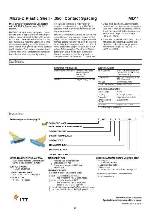
PCB ordering information - page 30SERIES-INSULATOR STYLE-MATERIAL SERIES-INSULATOR STYLE-MATERIALMDB - Screw mounting-Diallyl phthalate MDVB - Screw mounting-Polyester H -Insulated solid or stranded wire L -Uninsulated solid wireS -Solder pot to accept #26 AWG max.harness wire.No designator - No hardware - standard mounting .091 (2.31) hole diameterP -JackpostK -Jackscrew-standard L -Jackscrew-low profile F -Float mountM -Military specification hardware, see page 13.1-.050 (1.27) centers9-15-21-25-31-37-51. See page 9P -Pin S - SocketCONTACT SPACIN GCONTACT ARRAN G EMENTCONTACT TYPECONTACT SPACIN G CONTACT ARRAN G EMENT CONTACT TYPE TERMINATION TYPE TERMINATION TYPELOC K IN G H AR DW ARE (SCRE W MOUNTIN GONLY )TERMINATION CO D E LOC K IN G H AR DW AREM D** 1-9P H 001P(H) 001 - 18",7/34strand, #26 AWG, MIL-W-16878/4,T ype E T eflon, Y ellow.(H) 003 - 18",7/34strand, #26 AWG, MIL-W-16878/4,T ype E T eflon, color coded to MIL-S T D-681System I.(L) 1 - 1/2"uninsulated solid #25 AWG gold plated copper.(L) 2 - 1"uninsulated solid #25 AWG gold plated copper.TERMINATION CO D ERo H S COMPLIANCERSee page 79 and 81for additional codesDimensions shown in inch (mm)Specifications and dimensions subject to changeHow to OrderMicrominiature Rectangular Connectors with MICRO-Pin Contacts on .050 (1.27)centers.MICRO-D microminiature rack/panel connec-tors are used in applications requiring highly reliable, extremely small, lightweight connec-tors. These connectors are available in 2 insu-lator materials, 2 mounting variations, 7 shell sizes accommodating from 9 to 51 contacts and a special arrangement of 5 micro contacts and 2 coaxials. The insulator materials listed give the MICRO-D connector wide versatility in most applications required by industry.ITT can also terminate a wide variety of stranded or solid wire directly to MICRO-D contacts, which is often desirable in high den-sity arrangements.MICRO-D connectors can also be custom har-nessed to meet any customer requirement of single or multiple connectors. Pigtail lead and harness description must be given by the cus-tomer. A typical description would be: .5" #25AWG, gold plated copper leads or 18" of #26yellow, Teflon-insulated, Type E wire. Shown below are various methods of termination.Consult customer service for any routine or complex harnessing of MICRO-D connectors.•Glass-filled diallyl phthalate thermoset material used in high temperature applica-tions that is immune to cleaning solvents.It also has excellent dielectric properties.Temperature range: -65˚F to +300˚F (-55˚C to +149˚C).•Glass-filled polyester thermoplastic that is not affected by cleaning solvents and exhibits excellent dielectric properties.Temperature range: -55˚F to +257˚F (-65˚C to +125˚C).SpecificationsMATERIALS AND FINISHESShell/Insulator (One Piece)MD/MDB: Glass-filledthermoset plastic MDV/MDVB: Thermoplastic ELECTRICAL DATA MECHANICAL FEATURES No of ContactsSize or Length Coupling PolarizationContact Spacing Centers Shell StylesConsult factory for availabilty.Coaxial CableWire SizeContact Termination -9to 51: (1 arrangement of 5 contacts and 2 coaxials - for screw mount only)-7sizes-Friction/jackscrews-Keystone-shaped shells -.050 (1.27mm)-Plug and receptacle-RG-178/U (Not available for MD clip mount)-#24 thru #32 AWG -Multi-indent crimp-Copper alloy, gold plateContactsDimensions shown in inch (mm)Specifications and dimensions subject to changeStandard Wire Termination CodesCavity #1 black*The following termination codes are listed for your information. For additional codes please refer to Appendix on page 79 and 81. All wire lengths are minimum.#26 A WG per MIL-W-16878 Type E Teflon ,stranded.H arness Typ e (H)L ength 3(76.2)6(152.4)8(203.2)10(254.0)12(304.8)18 (457.2)20(508.0)24(609.6)30(762.0)36(914.4)48(1219.2)72(1828.8)120(3048.0)H020H019H026H029H028H001H038H009H010H011H013H017H042H027H016H034H025H002H003H023H004H005H006H048H046H041L61L 56L 57L 39L 58L 1L 14L2L 7L6L 16L 10.125(3.18).150 (3.81).190(4.83).250 (6.35).375(9.52).500 (12.70).750 (19.05)1.000 (25.40)1.500 (38.10)2.000 (50.80)2.500 (63.50)3.000 (76.20)All Y ell o w Co l o r Cod e d*T erminati o n Cod eL ength #25A WG G old P lated CopperS o li d U ninsulate d Typ e (L)With Screw Mounting Holes (Conforms to MIL-DTL-83513)MDB.110(2.79)MAX..154(3.91)(5.08)MAX.Solder PotSolder PotGlass-filled Diallyl Phthalate Plastic InsulatorMDVBGlass-filled Polyester Plastic InsulatorRPart Number by Shell Size Add lead type and length, see Part Number Explanation.Weight given is with 1/2", uninsulated solid #25 AWG gold plated copper pigtails.*****AMax.B Max.C Max.D Max.E Max.F ±.005Avg.Weight***±5% (oz.)±5% (gm.)MDB1-9S**MDB1-15P**MDB1-15S**MDB1-21P**MDB1-21S**MDB1-25P**MDB1-25S**MDB1-31P**MDB1-31S**MDB1-37P**MDB1-37S**MDB1-51P**MDB1-51S**MDVB1-9S**MDVB1-15p**MDVB1-15S**MDVB1-21P**MDVB1-21S**MDVB1-25P**MDVB1-25S**MDVB1-31P**MDVB1-31S**MDVB1-37P**MDVB1-37S**MDVB1-51P**MDVB1-51S**.788 (20.02).788 (20.02).938 (23.82)1.088 (27.64)1.088 (27.64)1.188 (30.18)1.188 (30.18)1.338 (33.98)1.338 (33.98)1.488 (37.80)1.488 (37.80)1.438 (36.52)1.438 (36.52).292 (7.42).380 (9.65).442 (11.23).592 (15.04).680 (17.27).692 (17.58).780 (19.81).842 (21.39).930 (23.62).992 (25.20)1.080 (27.43).942 (23.93)1.030 (26.16).408 (10.36).408 (10.36).588 (14.17).708 (17.98).708 (17.98).808 (20.56).808 (20.56).958 (24.33).958 (24.33)1.108 (28.14)1.108 (28.14)1.058 (26.87)1.058 (26.87).173 (4.39).173 (4.39).173 (4.39).173 (4.39).173 (4.39).173 (4.39).173 (4.39).173 (4.39).173 (4.39).173 (4.39).173 (4.39).220 (5.59).220 (5.59).218 (5.54).218 (5.54).218 (5.54).218 (5.54).218 (5.54).218 (5.54).218 (5.54).218 (5.54).218 (5.54).218 (5.54).218 (5.54).260 (6.60).260 (6.60).565 (14.35).565 (14.35).715 (18.16).865 (21.97).865 (21.97).965 (24.51).965 (24.51)1.115 (28.32)1.115 (38.32)1.265 (32.13)1.265 (32.13)1.215 (30.86)1.215 (30.86).026 (0.73).025 (0.70).038 (1.10).053 (1.50).050 (1.40).063 (1.80).056 (1.60).080 (2.30).073 (2.10).086 (2.45).076 (2.15).109 (3.10).093 (2.64)Dimensions shown in inch (mm)Specifications and dimensions subject to changeMD*B-PCB connectors use standard MD*B all plastic shells and are designed for use with flex circuitry, printed circuit and multi-layer boards. They are easily mounted and soldered and provide high density/high reliability in board-to-board and board-to-cable applica-tions. While being similar to the MDM-PCB connectors, the MD*B-PCB connectors are all plastic, extremely small, and lightweight yet rugged enough for use in the most demanding applications.MD*B-PCB connectors are available inseven shell sizes with 9 to 51 contacts in the popular 90°narrow profile PCB termination,with a variety of tail lengths for varying boardthickness.How to OrderSERIESCONTACT ARRANGEMENT CONTACT TYPE CTERMINATION TYPE THARDWAREHTERMINATION TAIL LENGTH TMODIFICATION CODES C(Consult Factory)MMD*B--37S CBR ** * *L39RoHS COMPLIANCE RJackpost mounting for use with locking hard-ware is also available.If the connectors shown in the catalog do not meet the requirements of your applica-tions, a special shape, size or layout using the basic all plastic shell can be made avail-able. For further technical and applications information, contact customer service.CONNECTOR SERIES MDVB, MDBCONNECTOR ARRANGEMENT9, 15, 21, 25, 31, 51CONTACT TYPES =Socket P =PinTERMINATION TYPECBR = 90°Narrow Profile PCB Terminations HARDWAREP =JackpostM7 = Jackposts, M635135-07No Letter = Less HardwareTERMINATION TAIL LENGTH CODESNONE –.109 (2.77) ±0.15 (0.38) Standard L61– .125 (3.18)L66– .150 (3.81)L57– .190 (4.83)L39–.250 (6.35)L58– .375 (9.52)Dimensions shown in inch (mm)Specifications and dimensions subject to changeCBR Series (90˚ Mounting Narrow Profile)TYP ..186 (4.72) PLUG 9-15-21-25 VIEW*FOR 31: 1.085 (27.56) MAX. FOR 37: 1.185 (30.10) MAX. FOR 51: 1.225 (31.12) MAX.I A. TYPPCB Termination Arrangements (Viewed from bottom of connector, on PCB solder side.)Indentification number shown for plug connector, use reverse order for socket connector..083.020.0209Contacts15 Contacts21 Contacts 25Contacts51 Contacts37 Contacts31 ContactsAll Termination Configurations .100 (2.54) x .100 (2.54) Grid Pattern, Offset .050 (1.27)*For jackpost locking add letter "P" or "M7".NOTE: Standard lead termination is #24 AWG, solid copper, solder or tin dipped.Part Number By Shell Size MD*B-9PCBR*MD*B-9SCBR*MD*B-15PCBR*MD*B-21PCBR*MD*B-21SCBR*MD*B-25PCBR*MD*B-25SCBR*MD*B-31PCBR*MD*B-31SCBR*MD*B-37PCBR*MD*B-37SCBR MD*B-51PCBR*MD*B-51SCBR.788 (20.01).938 (23.82)1.088 (27.63)1.088 (27.63)1.188 (30.17)1.188 (30.17)1.338 (33.98)1.338 (33.98)1.488 (37.79)1.488 (37.79)1.438 (36.52)1.438 (36.52).565 (14.35).715 (18.16).865 (21.97).865 (21.97).965 (24.51).965 (24.51)1.115 (28.32)1.115 (28.32)1.265 (32.13)1.265 (32.13)1.215 (30.86)1.215 (30.86).292 (7.42).525 (13.34).592 (15.04).675 (17.14).692 (17.58).775 (19.68).842 (21.39).925 (23.50).994 (25.25)1.075 (27.30).942 (23.93)1.026 (26.06).218 (5.54).218 (5.54).218 (5.54).218 (5.54).218 (5.54).218 (5.54).218 (5.54).218 (5.54).218 (5.54).218 (5.54).258 (6.55).258 (6.55).134 (3.40).218 (5.54).134 (3.40).218 (5.54).134 (3.40).218 (5.54).134 (3.40).218 (5.54).134 (3.40).218 (5.54).177 (4.50).258 (6.55).420 (10.67).420 (10.67).420 (10.67).420 (10.67).420 (10.67).420 (10.67).420 (10.67).420 (10.67).520 (13.21).520 (13.21).550 (13.97).550 (13.97).250 (6.35).250 (6.35).250 (6.35).250 (6.35).250 (6.35).250 (6.35).250 (6.35).250 (6.35).250 (6.35).250 (6.35).300 (7.62).300 (7.62).230 (5.84).130 (3.30).130 (3.30).130 (3.30).130 (3.30).130 (3.30).130 (3.30).130 (3.30).130 (3.30).130 (3.30).150 (3.81).150 (3.81)A Max.B±.005 (0.13)G±.010 (0.25)H±.010 (0.25)C Max.D Max.E Max.F Max.Dimensions shown in inch (mm)MDB Coaxial Series with Screw Mounting HolesMDB connectors with two coaxial and five MICRO-PIN TM /MICROSOCKET TM contacts. Crimp-type coaxial contacts accommodate RG-178/U cables. A plastic insertion/extraction tool is supplied with each connec-tor assembly having removable coaxial assembly.How to Order - MDB CoaxialSERIESMDB1-7C2****SHKSERIESMicro-D CoaxialNo Letter - Coaxial assemblyinstalled and nonremovable RO - coaxial assembly ordered serparatelyRA - Coaxial shipped assembled but uninstalled See Standard Wire TerminationConsult customer serviceNo letter - No hardware*Not available with removalbe coax cable type connectors RO and RA.standard mounting. 091 (2.31) hole diameter F -FloatK -Jackscrew (standard)L -Jackscrew (low profile)P -JackpostCode on page 29. Coaxial cable will beRG-178U unless otherwise specified; length will be same as wire modification.P -Pin S -Socket L -Uninsulated, solid wireH -Insulated, solid or stranded S -Solder pot*1-.050 (1.27) centers...................7 (2)SIGNAL CONTACT SPACING TOTAL CONTACT CAVITIES NUMBER OF COAXIALS SIGNAL CONTACT SPACING TOTAL CONTACT CAVITIES NUMBER OF COAXIALS COAXIAL TYPECOAXIAL TYPESIGNAL CONTACT TYPE SIGNAL CONTACT TYPESIGNAL CONTACT LEAD TYPE SIGNAL CONTACT LEAD TYPESIGNAL CONTACT LEAD LENGTH SIGNAL CONTACT LEAD LENGTH MODIFICATIONHARDWAREMODIFICATION HARDWARERoHS COMPLIANCE RHow to Order - Coaxial Cable AssembliesSERIESMDCCS** * *COAXIAL CABLE CONTACT TYPE CONTACT TYPE COAXIAL CABLE TYPECOAXIAL CABLE TYPE COAXIAL CABLE LENGTHCOAXIAL CABLE LENGTHSERIES MDP -Pin(used with socket side connection)S -Socket(used with pin type connection)See Standard Wire TerminationCodes on page 29. Coaxial cable will be RG-178U unless otherwise specified; length will be the same as wire modfication.1-RG178/UCOAXIAL CABLE CCRoHS COMPLIANCE RDimensions shown in inch (mm)Specifications and dimensions subject to changeDimension - MDB Coaxial SeriesPlugReceptacle(See page 9 for layouts)Part Numberby Shell SizeMDB1-7C2P*MDB1-7C2S*.510 (12.95).602 (15.29)* Add lead type and length, see Part Number Explanation.** Weight given is with 7 inch (177.80) insulated leads, #26 AWG silver plated copper pigtails and RG178/U coaxials..204 (5.18).185 (4.70).298 (7.57).279 (7.09).782 (19.86).782 (19.86).395 (10.03).375 (9.52).510 (12.95).540 (13.72).290 (8.30).273 (7.80)A Ma x.B Ma x.C Ma x.E Ma x.E 1Ma x.D +_.005 (0.13)Av g .W eight**(oz)+_5% (gm .)+_5%TWO MTG. HOLES RO AND RA COAXESRO AND RA COAXESMounting Hardware Views (Sizes 9-51)This hardware supplied unassembled.Screw Lock Assembly90˚ Angle Mounting BracketDescriptionScrew Lock Assembly Jackpost Kit322-9500-000 320-9505-000015-9516-000 .100 (2.54) .122 (3.10) .257(6.53).215(5.46)015-9516-000 Mounting Bracket, 90˚ Angle- MD*1for 9 thru 37 Shell Sizes MD*1for 51 Shell SizeNOTES: Screw lock assembly (322-9500-000) can be used for front front mounting. Jackpost kit(320-9505-000) consists of 2 assemblies, shipped unassembled.Part Number ±.005 (0.13)Max.*NOTE: Torque value is 4.0 in/lbs max. REF. ONLY_.003_0.08)FACEFACECONNECTOR HEX HEAD -Jackscrew - (L) Low ProfileJackscrew - (K) StandardThis hardware is factory installed.Shown here is a cutaway view of the float mount for the MD connector.The basic shell dimensions are the same for the float mount and the screw mounting hole configurations. View shown is for standard float mount front panel mounting. Reverse mounting is available on request.*NOTE: Torque values are as follows: Low Profile Jackscrew (L)-2.5 in/lbs Standard Jackscrew (K)-2.5 in/lbsDimensions shown in inch (mm)Specifications and dimensions subject to changeMounting Hardware to Military Specification (Sizes 9 - 51) PER MIL-DTL-83513/5This hardware supplied unassembled.Jackscrew - (L) Low profile *.062 (1.57)HEX. (REF.).092 (2.34) DIA.Allen headPlug and Receptacle Low and High Profile Slotted HeadJackpost AssemblyDescriptionSlotted Head Jackscrew Assy Low ProfileSlotted Head Jackscrew Assy High Profile Allen Head Jackscrew Assy Low Profile Allen Head Jackscrew Assy High Profile Jackpost Assy-05-06-02-03-07M5M6M2M3M7320-9508-025320-9508-027320-9508-026320-9508-028320-9505-033M83513/5Mode Code Part Number ThreadJackpost Bushing (For Rear Panel Mounting)MATING FACE.126 (3.20).125 (3.18)DIA.TYP .+.005 (0.13)3/32 (2.4)1/16 (1.6)3/64 (1.2)1/32 (0.8).092/.087 (2.34/2.21).061/.056 (2.34/1.42).047/.042 (1.19/1.07).030/.025 (0.76/0.64)320-9505-007320-9505-006320-9505-005320-9505-0049152125313751.379 ( 9.63).529 (13.44).679 (17.25).779 (19.79).929 (23.60)1.079 (27.41)1.029 (26.14).219 (5.56).219 (5.56).219 (5.56).219 (5.56).219 (5.56).219 (5.56).261 (6.63).565 (14.35).715 (18.16).865 (21.97).965 (24.51)1.115 (28.32)1.265 (32.13)1.215 (30.86)*2Jackposts, 2nuts, 2washers .Panel Thickness A Dim.Jackpost Kit Number*A+.004 (0.10)-.000 (0.00)Shell SizePlug and Receptacle DimensionsB +.004 (0.10)-.000 (0.00)C +_.005(0.13)NOTE: Torque value for jackpost 2.5 in /lbsPanel Mounting Dimensions.200 ±.005Plug and ReceptacleRear MountedPlug and Receptacle Front Mounted Plug Front Mounted Receptacle Rear Mounted.300 ±.005Dimensions shown in inch (mm)Specifications and dimensions subject to changePanel CutoutsFigure 1Front Mounting+.005 (0.13) R TYP -.000 (0.00)Figure 2Rear MountingFigure 3Edgeboard MountingNOTES:1. 2. 3. 123123123123123123123.409 (10.39).379 ( 9.63)-.559 (14.20).529 (13.44)-.709 (18.00).679 (17.25)-.809 (20.55).779 (19.79)-.959 (24.36).929 (23.60)-1.109 (28.17)1.079 (27.41)-1.059 (26.90)1.029 (26.14)-.172 (4.37).219 (5.56)-.172 (4.37).219 (5.56)-.172 (4.37).219 (5.56)-.172 (4.37).219 (5.56)-.172 (4.37).219 (5.56)-.172 (4.37).219 (5.56)-.215 (5.46).261 (6.63)-.570 (14.48).570 (14.48).570 (14.48).720 (18.29).720 (18.29).720 (18.29).870 (22.10).870 (22.10).870 (22.10).970 (24.64).970 (24.64).970 (24.64)1.120 (28.45)1.120 (28.45)1.120 (28.45)1.270 (32.26)1.270 (32.26)1.270 (32.26)1.220 (30.99)1.220 (30.99)1.220 (30.99).089 (2.26).089 (2.26).089 (2.26).089 (2.26).089 (2.26).089 (2.26).089 (2.26).089 (2.26).089 (2.26).089 (2.26).089 (2.26).089 (2.26).089 (2.26).089 (2.26).089 (2.26).089 (2.26).089 (2.26).089 (2.26).089 (2.26).089 (2.26).089 (2.26)9152125313751A+.004 (0.10)-.000 (0.00)B+.004 (0.10)-.000 (0.00)C+.005 (0.13)-.000 (0.00)D+.005 (0.13)-.000 (0.00)Cutout Figure Size Front mounting (figure 1) and rear mounting (figure 2) accommodates #2-56 screws.Front mounting is preferred. However, when rear mounting is necessary. use detail on previous page.Edgeboard mounting bracket (figure3) uses #2-56 screws. Dimension .450 ± .002 (11.43 ± 0.05) locates theMD receptacle flush with the end of the board.PlugMDGlass-filled Diallyl Phthalate Plastic InsulatorMDVGlass-filled Polyester Plastic InsulatorSolder PotSolder PotReceptacle.130(3.30)(5.33)(4.32).170(4.32)PCB ordering information - page 30SERIES-INSULATOR STYLE-MATERIAL SERIES-INSULATOR STYLE-MATERIALMD - Clip mounting -Diallyl phthalate MDV - Clip mounting-Polyester H-Insulated solid or stranded wire L -Uninsulated solid wireS -Solder pot to accept #26 AWG max.harness wire.No designator - No hardware - standard mounting .091 (2.31) hole diameterNot available in clip mounting.See page 79 and 81for additional codes.***(H) 001 - 18", 7/34strand ,#26 AWG ,MIL-W-16878/4, T ype E T eflon ,Y ellow.(H) 003 - 18", 7/34strand ,#26 AWG ,MIL-W-16878/4, T ype E T eflon ,colorcoded to MIL-S T D-681 System I.(L) 1 - 1/2"uninsulated solid #25AWG gold plated copper.(L) 2 - 1"uninsulated solid #25AWG gold plated copper.1-.050(1.27) centers9-15-21-25-31*-37-51.See page 7P -Pin S - Soc k etCONTACT SPACIN GCONTACT ARRAN G EMENTCONTACT TYPECONTACT SPACIN G CONTACT ARRAN G EMENT CONTACT TYPE TERMINATION TYPE TERMINATION TYPETERMINATION CO D E **TERMINATION CO D E LOC K IN G H AR DW AREM D1-9PH001PRo H S COMPLIANCERPart Number by Shell Size MD1-9P**MD1-9S**MD1-15P**MD1-15S**MD1-21P**MD1-21S**MD1-25P**MD1-25S**MD1-37P**MD1-37S**MD1-51P**MD1-51S**MDV1-9-P**MDV1-9S**MDV1-15P**MDV1-15S**MDV1-21P**MDV1-21S**MDV1-25P**MDV1-25S**MDV1-37P**MDV1-37S**MDV1-51P**MDV1-51S**A Max.B Max.C Max.D Max.E Max.Avg. Weight***±5% (oz.)/±5% (gm.).512 (13.00).512 (13.00).662 (16.81).662 (16.81).812 (20.62).812 (20.62).912 (23.16).912 (23.16)1.212 (30.78)1.212 (30.78)1.162 (29.51)1.162 (29.51).292 (7.42).376 (9.55).442 (11.23).526 (13.36).592 (15.04).676 (17.17).692 (17.58).776 (19.71).992 (25.20)1.076 (27.33).942 (23.93)1.026 (26.06).405 (10.29).405 (10.29).555 (14.10).555 (14.10).705 (17.91).705 (17.91).805 (20.45).805 (20.45)1.105 (28.07)1.105 (28.07)1.055 (26.80)1.055 (26.80).170 (4.32).170 (4.32).170 (4.32).170 (4.32).170 (4.32).170 (4.32).170 (4.32).170 (4.32).170 (4.32).170 (4.32).213 (5.41).213 (5.41).215 (5.46).215 (5.46).215 (5.46).215 (5.46).215 (5.46).215 (5.46).215 (5.46).215 (5.46).215 (5.46).215 (5.46).258 (6.55).258 (6.55).026 (0.73).026 (0.73).038 (1.10).035 (1.00).053 (1.50).050 (1.40).063 (1.80).056 (1.60).086 (2.45).076 (2.15).109 (3.10).093 (2.65)How to OrderWith Clip Mounting SlotsMicro-D Plastic Shell - .050" Contact Spacing MD**Panel Mounting HardwareClip MountingDescriptionDimensions (Clip Mounting Only)Coupling Retention Clip(see Figure 2)Mounting Screw Brackets(see Figures 1 and 3)PanelMounting KeyEdgeboard Mounted(see Figure 4)Plug and ReceptacleRear MountedPlug and ReceptacleFront Mounted Receptacle Rear MountedPart Number201-9100-000294-9100-000015-9100-000015-5009-000MD51428-1Panel Mounting KeyMounting Key and Coupling Clip AssemblyMounting Screw BracketEdgeboard Mounting BracketEdgeboard Mounting Bracket andCoupling Clip AssemblyMust be ordered separately; specify left and right hand for completeassembly.Must be ordered separately; assembly contains set of left and righthand types.******Illustrated is the recommended method of front mountingwith metal panel mounting keys. Panel mounting keys areavailable with or without coupling retention clips.For front mounting,place the rear of the connector thruthe panel cutout.With the mounting flange against thepanel,fully insert the panel mounting keys thru the slotsin the flange and thru the panel cutout.Retaining thekeys in this position, bend them outward against the rearof the panel.When mating a front mounted connectorwith an unmounted connector, a coupling retention clipassembly may be used to securely lock the two together.Mounting screw brackets are available and may be usedinstead of the panel mounting keys.Panel CutoutsFigure 1Figure 3Rear MountingFigure 4Edgeboard MountingFigure 2Front Mounting.).).MAX. (TYP.)A panel thickness of 1/8" 3.17mm) maximum is recommended for ease of tab bendingwhen a panel mounting key & clip assembly or edgeboard mounting brackets are used.Front mounting is preferred. However, when rear mounting is necessary, use figure 3 fordimensions.Figure 4 is for edge board mounting bracket or edgeboard clip assembly. The .184 +_ .0022.67 +_ 0.05) dimension locates the MD socket insulator flush with the end of the board.Screw brackets (015-9100-000) will accommodate #2-56 screws.Front mounting(Figure 1)and rear mounting(Figure 3)accommodate#2-56screws.1.2.3.4.5.ShellSize91521253751123412341234123412341234.408 (10.36).408 (10.36).378 ( 9.60).400 (10.16).588 (14.94).588 (14.94).528 (13.28).550 (13.97).738 (18.75).738 (18.75).678 (17.27).700 (17.78).838 (21.29).838 (21.29).778 (19.76).800 (20.32)1.138 (28.91)1.138 (28.91)1.078 (27.38)1.100 (27.94)1.088 (27.64)1.088 (27.64)1.028 (26.11)1.050 (26.67).172 (4.37).172 (4.37).217 (5.51).091 (2.31).172 (4.37).172 (4.37).217 (5.51).091 (2.31).172 (4.37).172 (4.37).217 (5.51).091 (2.31).172 (4.37).172 (4.37).217 (5.51).091 (2.31).172 (4.37).172 (4.37).217 (5.51).091 (2.31).215 (5.46).215 (5.46).260 (6.60).091 (2.31).650 (16.51)-.650 (16.51)-.795 (20.19)-.795 (20.19)-.945 (24.00)-.945 (24.00)-1.045 (26.54)-1.045 (26.54)-1.345 (34.16)-1.345 (34.16)-1.295 (32.89)-1.295 (32.89)-.089 (2.26)-.089 (2.26)-.089 (2.26)-.089 (2.26)-.089 (2.26)-.089 (2.26)-.089 (2.26)-.089 (2.26)-.089 (2.26)-.089 (2.26)-.089 (2.26)-.089 (2.26)-CutoutFigureA+.004 (0.10)-.000 (0.00)B+.004 (0.10)-.000 (0.00)C+.004 (0.10)-.000 (0.00)D+.005 (0.13)-.000 (0.00)38Dimensions shown in inch (mm)Specifications and dimensions subject to change 元器件交易网。
ABB电源电缆接头目录说明书

—C ATALOGPower cable compression lugs Installation of solderless compression lugs on power cables23—Compression power cable lugs solutions4 – 6I ntroduction7 – 20S pec-Kon®lugs21 – 28C olor-Keyed®lugs29 – 34T ools and accessoriesStrands cut Nicked strandsStrip length too short Strip length too long4CO M PR E S S I O N P OW E R C A B LE LU G S C ATA LO GThis method allows electrical workers to make in-stallations with little effort and at a considerablesavings in time. The benefit, of course, is a high-quality connection at a low installed cost.—Compression power cable lugsThe ABB method is betterThe ABB method of installing compression lugs on power cables isdesigned to provide a high degree of reliability in electrical wiring.STEP 2Carefully strip the insulation on de-energizedwires to avoid nicking or cutting conductors.Strip the insulation to the proper length so thatconductors can be fully inserted into the lugbarrel.Just four easy steps to a perfect connection!*STEP 1Determine the proper lug for the cable size beingused. Lugs are marked to show cable size.—* Pictures and expla-nations are based onSpec-Kon® metricproduct range. Tools,dies, lugs and markingsmay differ for eachproduct rangeCable size5STEP 4STEP 3Die CodeMarkingDie Code MarkingSelect the proper installing die and appropriate tool.Locate tool with correct die in proper position on lug and activate tool.When making multiple crimps, make the first crimp nearest the tongue and work towards the barrel end.When properly crimped, the die code number will be embossed on the lug for easy inspection to determine if correct die and lug combination was used.BarrelTongue1e crimp 2e crimpDie location for compressionDie code embossedRefer to the instruction sheet supplied with the lugs for information regarding strip length, die selection and number of compressions required.6CO M PR E S S I O N P OW E R C A B LE LU G S C ATA LO GABB method* dies are designed to produce a circumferential, hex- or diamond-shaped com-pression rather than a simple indent. Precision dies are an integral part of the ABB method. The precision hardened steel dies exert tremendous, controlled pressure on the lug and conductor. The dies compress the lug around the cable, convert-ing the round strands to hexagonal or diamond shapes and forming the strands and lug into a solid mass. Each die is designed so that all con-ductors receive the same amount of compression force.The circumferential compression creates a large area of high-pressure contact between cable and lug which, in turn, assures high conductivity, low resistance, and high pullout values which exceed UL/IEC/CE requirements. These features result in a permanent, low installed cost connection. You can install it, and forget it.—HEX crimping technology Precision dies form a solid homogenous massThe ABB method utilizing compression tools with matching dies forms the lug and conductor into a solid, homogenous mass to provide an optimum electrical bond between lug and conductor.—* Pictures and expla-nations are based on the Spec-Kon® metric product range. Tools, dies, lugs and markings may differ for each product rangeThe ABB system tells you where to place the installing die.Before compression, a typical cross section of cable and lug consists of about 75% metal and 25% air.After air compression by the ABB Method, the cross section looks like this, nearly 100% metal with v irtually no air spaces.Die code embossed7* For other tools compatibility, please contact your ABB local contact or check our website for your local contact numberConductorSpec-Kon ®25—Spec-Kon® lugs Quick guide—Spec-Kon® die selector Quick guide8CO M PR E S S I O N P OW E R C A B LE LU G S C ATA LO G—Spec-Kon ® lugsCopper / Straight – one hole typeApplication • C opper tin plated Metric Compression Lug for power cables for rated voltage up to 36kV. From 6 to 400 mm 2• S pecially designed to accommodate both stranded (class 2) and flexible (class 5) power cables according to IEC 60228Characteristics• S traight - one hole lug with die code marking to assist installation work and inspection• Hole inspection to ease installation control• Chamfer barrel to assist installation work Material • C opper. Comply to EN13600Surface • T in plated Certification• Comply to IEC 61238 - CE declarationCK25602889—Spec-Kon ® lugsCopper / Straight – one hole typeApplication • C opper tin plated Metric Compression Lug for power cables for rated voltage up to 36kV. From 6 to 400 mm 2• S pecially designed to accommodate both stranded (class 2) and flexible (class 5) power cables according to IEC 60228Characteristics• S traight - one hole lug with die code marking to assist installation work and inspection• Hole inspection to ease installation control• Chamfer barrel to assist installation work Material • C opper. Comply to EN13600Surface • T in plated Certification• Comply to IEC 61238 - CE declarationCK2510CO M PR E S S I O N P OW E R C A B LE LU G S C ATA LO G––Spec-Kon ® lugsCopper / 45° – one hole typeApplication • C opper tin plated Metric Compression Lug for power cables for rated voltage up to 36kV. From 6 to 400 mm 2• S pecially designed to accommodate both stranded (class 2) and flexible (class 5) power cables according to IEC 60228Characteristics• 45 degrees - one hole lug with die code marking to assist installation work and inspection• Hole inspection to ease installation control• Chamfer barrel to assist installation work Material • C opper. Comply to EN13600Surface • T in plated Certification• Comply to IEC 61238 - CE declarationCFBIDCK2560288Copper / 45° – one hole typeApplication • C opper tin plated Metric Compression Lug for power cables for rated voltage up to 36kV. From 6 to 400 mm 2• S pecially designed to accommodate both stranded (class 2) and flexible (class 5) power cables according to IEC 60228Characteristics• 45 degrees - one hole lug with die code marking to assist installation work and inspection• Hole inspection to ease installation control• Chamfer barrel to assist installation work Material • C opper. Comply to EN13600Surface • T in plated Certification• Comply to IEC 61238 - CE declarationCFBIDCK25Application • C opper tin plated Metric Compression Lug for power cables for rated voltage up to 36kV. From 6 to 400 mm 2• S pecially designed to accommodate both stranded (class 2) and flexible (class 5) power cables according to IEC 60228Characteristics • 90 degrees - one hole lug with die code marking to assist installation work and inspection• Hole inspection to ease installation control• Chamfer barrel to assist installation work Material • C opper. Comply to EN13600Surface • T in plated Certification• Comply to IEC 61238 - CE declarationCDF BICopper / 90° – one hole typeCK2560288Application • C opper tin plated Metric Compression Lug for power cables for rated voltage up to 36kV. From 6 to 400 mm 2• S pecially designed to accommodate both stranded (class 2) and flexible (class 5) power cables according to IEC 60228Characteristics • 90 degrees - one hole lug with die code marking to assist installation work and inspection• Hole inspection to ease installation control• Chamfer barrel to assist installation work Material • C opper. Comply to EN13600Surface • T in plated Certification• Comply to IEC 61238 - CE declarationCDF BICopper / 90° – one hole typeCK2560288Copper / Straight long barrel – one hole typeApplication • C opper tin plated Metric Compression Lug for power cables for rated voltage up to 36kV. From 6 to 400 mm 2• S pecially designed to accommodate both stranded (class 2) and flexible (class 5) power cables according to IEC 60228Characteristics• S traight long barrel - one hole lug with die code marking to assist installa-tion work and inspection• Hole inspection to ease installation control• Chamfer barrel to assist installation work Material • C opper. Comply to EN13600Surface • T in plated Certification• Comply to IEC 61238 - CE declarationCK2560288Copper / Straight long barrel – one hole typeApplication • C opper tin plated Metric Compression Lug for power cables for rated voltage up to 36kV. From 6 to 400 mm 2• S pecially designed to accommodate both stranded (class 2) and flexible (class 5) power cables according to IEC 60228Characteristics• S traight long barrel - one hole lug with die code marking to assist installa-tion work and inspection• Hole inspection to ease installation control• Chamfer barrel to assist installation work Material • C opper. Comply to EN13600Surface • T in plated Certification• C omply to IEC 61238 - CE declarationCK25Copper / Straight – two hole typeApplication • C opper tin plated Metric Compression Lug for power cables for rated voltage up to 36kV. From 25 to 400 mm 2• S pecially designed to accommodate both stranded (class 2) and flexible (class 5) power cables according to IEC 60228Characteristics• S traight - two hole lug with die code marking to assist installation work and inspection• Hole inspection to ease installation control• Chamfer barrel to assist installation work Material • C opper. Comply to EN13600Surface • T in plated Certification• Comply to IEC 61238 - CE declarationCK25Copper / Straight long barrel – two hole typeApplication • C opper tin plated Metric Compression Lug for power cables for rated voltage up to 36kV. From 25 to 400 mm 2• S pecially designed to accommodate both stranded (class 2) and flexible (class 5) power cables according to IEC 60228Characteristics • S traight long barrel - two hole lug with die code marking to assist installa-tion work and inspection• Hole inspection to ease installation control• Chamfer barrel to assist installation work Material • C opper. Comply to EN13600Surface • T in plated Certification• Comply to IEC 61238 - CE declarationCK2560288Copper / Straight Narrow Tongue – one hole typeApplication • C opper tin plated Metric Compression Lug for Switchers and Breakers with reduced space terminal blocks. From 6 to 300 mm 2• S pecially designed to accommodate both stranded (class 2) and flexible (class 5) power cables according to IEC 60228Characteristics • S traight Narrow Palm - two hole lug with die code marking to assist instal-lation work and inspection• Hole inspection to ease installation control• Chamfer barrel to assist installation work Material • C opper. Comply to EN13600Surface • T in plated Certification• Comply to IEC 61238 - CE declarationCK25—Spec-Kon ® lugsCopper / Straight Narrow Tongue – one hole typeApplication • C opper tin plated Metric Compression Lug for Switchers and Breakers with reduced space terminal blocks. From 6 to 300 mm 2• S pecially designed to accommodate both stranded (class 2) and flexible (class 5) power cables according to IEC 60228Characteristics• S traight Narrow Palm - two hole lug with die code marking to assist instal-lation work and inspection• Hole inspection to ease installation control• Chamfer barrel to assist installation work Material • C opper. Comply to EN13600Surface • T in plated Certification• C omply to IEC 61238 - CE declarationCK25—Spec-Kon ® lugsCopper / Butt splicesApplication • C opper tin plated Metric Compression Butt Splices for power cables for rated voltage up to 36kV. From 6 to 400 mm 2• S pecially designed to accommodate both stranded (class 2) and flexible (class 5) power cables according to IEC 60228Characteristics • D ie code marking to assist installation work and inspection • Hole inspection to ease installation control• Chamfer barrel to assist installation work Material • C opper. Comply to EN13600Surface • T in plated Certification• C omply to IEC 61238 - CE declarationCK25—Color-Keyed® lugsQuick guideCK25—Color-Keyed® die selectorQuick guideConductor SizeColor-Keyed ®[mm 2]LugPart numberH-CK 240B-CK 240H-CK 400B-CK 400—* For other toolscompatibility, please contact your ABB local contact or check our website for your local contact numberCopper / Straight – one hole typeApplication • C opper tin plated Metric Compression Lug for power cables for rated Array voltage up to 36kV. From 6 to 400 mm2• I ntended for electricity distribution or industrial networks in which theyCopper / Straight – one hole typeApplication • C opper tin plated Metric Compression Lug for power cables for ratedvoltage up to 36kV. From 6 to 400 mm2• I ntended for electricity distribution or industrial networks in which theyCopper / 45 degrees – one hole typevoltage up to 36kV. From 6 to 240 mm2• I ntended for electricity distribution or industrial networks in which theycan be subjected to short-circuits of relatively high intensity and duration• S pecially designed to accommodate both stranded (class 2) and flexible(class 5) power cables according to IEC 60228Copper / 90 degrees – one hole typevoltage up to 36kV. From 6 to 240 mm2• I ntended for electricity distribution or industrial networks in which theyCopper/Straight - two hole typeApplication• C opper tin plated Metric Compression Lug for power cables for rated voltage up to 36kV. From 25 to 300 mm 2• I ntended for electricity distribution or industrial networks in which theycan be subjected to short-circuits of relatively high intensity and duration•Specially designed to accommodate both stranded (class 2) and flexible(class 5) power cables according to IEC 60228S traight - two holes lug with Color-Keyed® technology (error-free installation)• Hole inspection to ease installation control • Short Circuit resistance*• Chamfer barrel to assist installation work • Copper. Comply to EN13600• Tin plated • Comply to IEC 61238 - CE declaration—* Six short-circuits are applied after the 200th heat cycle (IEC 61238-1 total of 1000 Heat cycle test). The short-circuit current level shall be such that it raises the bare reference conductors from a temperature of ≤35 °C to a temperature between 250 °C and 270 °CCK25A W GFor other tools compatibility, please contact your ABB local contact or check our website for your local contact number/low-voltage/products/connectivity-groundingCKColor-Keyed® lugsQuick guide AWG copper lugs & splicesA W GCK—Color-Keyed® lugsQuick guide AWG cast copper lugs & splicesColor-Keyed® lugsQuick guide AWG aluminium lugs & splices—Tools and accessoriesHydraulic compression tools – Battery poweredBattery Hydraulic Compression Tool Set Product Ref.: B-CK 400GID Number: 7TCA131530R0002Characteristics- U seable dies: 155 series - C rimping range: 10-400 mm² - Crimping force: 140 kN- Weight: 4.9 kg without battery - Length: 330 mm - S cope of delivery: Tool , 2 batteries Bat-Li34, Charger BatC-230 MC,carrying case with die boxBattery Hydraulic Compression Tool Set Product Ref.: B-CK 240GID Number: 7TCA131530R0001Characteristics- U seable dies: 6 tons series - C rimping range: 6-240 mm² - Crimping force: 52 kN- Weight: 2.3 kg without battery - Length: 455 mm- Scope of delivery: Tool, 2 batteries Bat-Li34, Charger BatC-230, Carrying caseTools and accessoriesCompression tools, dies, pumps and accessoriesThe ABB compression tools with matching dies forms the lug and conductor into a solid, homogenous mass to provide an optimum electrical bond between lug and conductor.—Tools and accessoriesHydraulic compression tools – Hand and remote headManual Hydraulic Compression ToolProduct Ref.: H-CK 240GID Number: 7TCA131530R0014Characteristics- U seable dies: 6 tons series- C rimping range: 6 - 240 mm²- C rimping force: 52 kN- Weight: 2.8 kg- Length: 480 mmManual Hydraulic Compression Too lProduct Ref.: H-CK 400GID Number: 7TCA131530R0000Characteristics- U seable dies: 155 series- C rimping range: 10-400 mm²- Crimping force: 106 kN- Weight: 6.2 kg- Length: 580 mmRemote-Head Hydraulic Compression ToolProduct Ref.: T-CK 240GID Number: 7TCA131530R0003Characteristics- U seable dies: 6 tons series- C rimping range: 6 - 240 mm²- C rimping force: 55 kN- W eight: 1.72 kg- L ength: 260 mm- O perating pressure: 700 barRemote-Head Hydraulic Compression ToolProduct Ref.: T-CK 400GID Number: 7TCA131530R0004Characteristics- U seable dies: 155 series- C rimping range: 10 - 400 mm²- C rimping force: 108 kN- Weight: 3.6 kg- Length: 285 mm31—Tools and accessories Dies and die selector155-series Set die for Metric Compression Lugs Product Ref.: 155xxMCharacteristics- C ompatible with B-CK 400 / H-CK 400 / T- CK 400*- F rom 10 to 400 mm². Comply to IEC 61238- Available for metric Color-Keyed ® and Spec-Kon ®6 ton-series Set die for Metric Compression Lugs Product Ref.: 6tonxxMCharacteristics- C ompatible with B-CK 240 / H-CK 240 / T- CK 240*- F rom 6 to 240 mm². Comply to IEC 61238- Available for metric Color-Keyed ® and Spec-Kon ®* For other tools compatibility, please contact your ABB local contactConductorColor-Keyed ®Spec-Kon ®32CO M PR E S S I O N P OW E R C A B LE LU G S C ATA LO G—Tools and accessoriesHydraulic cutting tools – Battery, hand and remote headBattery Cutting Tool SetProduct Ref.: B-Cut 50GID Number: 7TCA131530R0006Characteristics- C utting capacity: max. 50 mm- C utting force: 25 kN- W eight: 2.1 kg less battery- L ength: 355 mm- A pplication: non-ferrous/ideally suited for cutting fine stranded conductors- F eatures: electronic overload protection and safety control lever- Scope of delivery: Tool, 2 batteries Bat-Li34, Charger BatC-230, Carrying caseHand Cutting Tool SetProduct Ref.: H-Cut 22GID Number: 7TCA131530R0005Characteristics- C utting capacity: max. 22 mm- C utting force: 39 kN- Weight: 2.8 kg- Length: 390 mm- A pplication: steelRemote-Head Cutting Tool SetProduct Ref.: T-Cut 20GID Number: 7TCA131530R0007Characteristics- C utting capacity: max. 40 mm- C utting force: 76 kN- W eight: 4 kg- Length: 340 mm- A pplication: steel- Operating pressure: 700 bar33—Tools and accessoriesHydraulic pumpsMobile Battery Operated Hydraulic Pump SetProduct Ref.: M-Pump 1300GID Number: 7TCA131530R0008Characteristics- O il delivery: 1.300 ml/min (low pressure) 200 ml/ min (high pressure)- O il filling: 600ml (400ml useable)- P rinciple: two parallel working 2-step piston pumps with rapid advance- P ower supply: 14.4 V battery (LiA-34) (useable with one or two batteries)- H ydraulic connection: Coupling Cejn series 115- D imensions (LxWxH): 380 x 205 x 240 mm- W eight: 7.7 kg less battery- W orking pressure 700bar (can be set from 150 - 850 bar by the manufacturer)- F eatures: - wired remote control 5m (included) - rotatable hydraulic coupling- S cope of delivery: - Mobile pump - 2 batteries Bat-Li 34 - 2 charger BatC-230Mobile Battery Operated Hydraulic Pump SetProduct Ref.: F-Pump 400GID Number: 7TCA131530R0009Characteristics- O il delivery: 0.4 l/min- Operating pressure: 700 bar (adjusted)- W eight: 15.7 kg- D imensions (LxWxH): 230 x 230 x 395 mm- O il fill: 1.2 l (0.8 l serviceable)- P ower supply: 230 V~ (370 W)- O peration: one-hand remote control with touch control- H ose coupling: CEJN-coupling series 115- Options: adjustable pump pressure from 150 to 850 bar by manufacturer- I ncluded in delivery: Electrohydraulic Fixed Pump, Quick coupling, Foot switch ( if requested)- T here is no hose included in this item.34CO M PR E S S I O N P OW E R C A B LE LU G S C ATA LO GBattery ChargerProduct Ref.: BatC-230GID Number: 7TCA131530R0011Characteristics- For recharge of BatC-230-P ower supply: 230 V / 50 Hz - Weight: 0.5 kg- Measures (L x W x H): 150 x 85 x 75 mm- Recharge time: LiIon (3,3 Ah) approx. 75 min.- NiCd (2,0 Ah) approx. 45 min.- NiMH (3,0 Ah) approx. 90 minLi-Ion BatteryProduct Ref.: Bat-Li 34GID Number: 7TCA131530R0010Characteristics- T echnology: Lithium Ion - V oltage: 14.4 V - Capacity: 3.3 Ah- Measures (L x W x H): 110 x 70 x130 mm - Weight: 0.56 kg- Charging time: approx. 75 min.- Useable Charger: BatC-230Power Supply for battery tower compression tool Product Ref.: Power-230GID Number: 7TCA131530R0012Characteristics- I nput: 220 - 240 V ca. 50-60 Hz 70 W - 800 W - O utput: 14.4 V - 5-60A - C onnection cable: 5 m - W eight: 0.8 kgHydraulic Hose 3 mProduct Ref.: HydT-3GID Number: 7TCA131530R0013Characteristics- H ose with Oilfill including coupling system (Nipple and coupler)- L ength of hose: 3 m- Working pressure max. 1000 bar- Coupling system Cejn Series 115—Tools and accessories Accessories3571345621 Rail & transportation |2 Power utility & renewable energy |3 Aerospace |4 Food beverage & agriculture |5 Commercial, institutional, residential |6 Automation, OEM, panel builders |7 Chemicals & pharmaceutical, mining & minerals |8 On & offshore, marine78—ABB products are part of your success Designed to perform9A K K 107045A 3839© Copyright 2017 ABB. All rights reserved.Specifications subject to change without notice.—ABB LtdElectrification Products Tower CourtFoleshill Enterprise Park Courtaulds Way Coventry CV6 5NX United KingdomTel: +44 (0) 333 999 9900Fax: +44 (0) 333 999 9901/uk。
MMSZ4xxxT1G系列和SZMMSZ4xxxT1G系列零点电阻电源器件的商品说明书

MMSZ4686T1G MMSZ4686T1G.MMSZ4xxxT1G Series, SZMMSZ4xxxT1G Series Zener Voltage Regulators 500 mW, Low I ZT SOD−123 Surface MountThree complete series of Zener diodes are offered in the convenient, surface mount plastic SOD−123 package. These devices provide a convenient alternative to the leadless 34−package style.Features•500 mW Rating on FR−4 or FR−5 Board•Wide Zener Reverse V oltage Range − 1.8 V to 43 V•Low Reverse Current (I ZT) − 50 m A•Package Designed for Optimal Automated Board Assembly •Small Package Size for High Density Applications•ESD Rating of Class 3 (>16 kV) per Human Body Model•SZ Prefix for Automotive and Other Applications Requiring Unique Site and Control Change Requirements; AEC−Q101 Qualified and PPAP Capable•These Devices are Pb−Free and are RoHS Compliant*Mechanical Characteristics:CASE:V oid-free, transfer-molded, thermosetting plastic case FINISH:Corrosion resistant finish, easily solderableMAXIMUM CASE TEMPERATURE FOR SOLDERING PURPOSES: 260°C for 10 SecondsPOLARITY:Cathode indicated by polarity band FLAMMABILITY RATING:UL 94 V−0MAXIMUM RATINGSRating Symbol Max Units Total Power Dissipation on FR−5 Board,(Note 1) @ T L = 75°CDerated above 75°C P D5006.7mWmW/°CThermal Resistance, (Note 2) Junction−to−Ambient R q JA340°C/WThermal Resistance, (Note 2) Junction−to−Lead R q JL150°C/WJunction and Storage Temperature Range T J, T stg−55 to+150°CStresses exceeding those listed in the Maximum Ratings table may damage the device. If any of these limits are exceeded, device functionality should not be assumed, damage may occur and reliability may be affected.1.FR−5 = 3.5 X 1.5 inches, using the minimum recommended footprint.2.Thermal Resistance measurement obtained via infrared Scan Method.*For additional information on our Pb−Free strategy and soldering details, please download the ON Semiconductor Soldering and Mounting Techniques Reference Manual, SOLDERRM/D.Cathode AnodeSee specific marking information in the device marking column of the Electrical Characteristics table on page 3 of this data sheet.DEVICE MARKING INFORMATIONSOD−123CASE 425STYLE 1Device Package Shipping†ORDERING INFORMATIONMARKING DIAGRAM†For information on tape and reel specifications, including part orientation and tape sizes, please refer to our T ape and Reel Packaging Specifications Brochure, BRD8011/D.MMSZ4xxxT1G SOD−123(Pb−Free)3,000 /Tape & ReelMMSZ4xxxT3G SOD−123(Pb−Free)10,000 /Tape & Reel xx= Device Code (Refer to page 3)M= Date CodeG= Pb−Free Package(Note: Microdot may be in either location)1SZMMSZ4xxxT1G SOD−123(Pb−Free)3,000 /Tape & ReelSZMMSZ4xxxT3G SOD−123(Pb−Free)10,000 /Tape & ReelELECTRICAL CHARACTERISTICS (T A = 25°C unless otherwise noted, V F = 0.9 V Max. @ I F = 10 mA)Symbol ParameterV Z Reverse Zener Voltage @ I ZTI ZT Reverse CurrentI R Reverse Leakage Current @ V RVR Reverse VoltageI F Forward CurrentV F Forward Voltage @ I FProduct parametric performance is indicated in the Electrical Characteristics for the listed test conditions, unless otherwise noted. Product performance may not be indicated by the Electrical Characteristics if operated under different conditions.ELECTRICAL CHARACTERISTICS (T A = 25°C unless otherwise noted, V F = 0.9 V Max. @ I F = 10 mA)Device*DeviceMarkingZener Voltage (Note 3)Leakage CurrentV Z (Volts)@ I ZT I R @ V RMin Nom Max m A m A VoltsMMSZ4678T1G CC 1.71 1.8 1.89507.51 MMSZ4679T1G CD 1.90 2.0 2.105051 MMSZ4680T1G CE 2.09 2.2 2.315041 MMSZ4681T1G CF 2.28 2.4 2.525021 MMSZ4682T1G CH 2.565 2.7 2.8355011 MMSZ4683T1G CJ 2.85 3.0 3.15500.81 MMSZ4684T1G CK 3.13 3.3 3.47507.5 1.5 MMSZ4685T1G CM 3.42 3.6 3.78507.52 MMSZ4686T1G CN 3.70 3.9 4.105052 MMSZ4687T1G CP 4.09 4.3 4.525042 SZMMSZ4687T1G CG6 4.09 4.3 4.525042 MMSZ4688T1G CT 4.47 4.7 4.9450103 MMSZ4689T1G CU 4.85 5.1 5.3650103 MMSZ4690T1G/T3G CV 5.32 5.6 5.8850104 MMSZ4691T1G CA 5.89 6.2 6.5150105 MMSZ4692T1G CX 6.46 6.87.145010 5.1 MMSZ4693T1G CY7.137.57.885010 5.7 MMSZ4694T1G CZ7.798.28.61501 6.2 MMSZ4695T1G DC8.278.79.14501 6.6 MMSZ4696T1G DD8.659.19.56501 6.9 MMSZ4697T1G DE9.501010.505017.6 MMSZ4698T1G DF10.451111.55500.058.4 MMSZ4699T1G DH11.401212.60500.059.1 MMSZ4700T1G DJ12.351313.65500.059.8 MMSZ4701T1G DK13.301414.70500.0510.6 MMSZ4702T1G DM14.251515.75500.0511.4 MMSZ4703T1G†DN15.201616.80500.0512.1 MMSZ4704T1G DP16.151717.85500.0512.9 MMSZ4705T1G DT17.101818.90500.0513.6 MMSZ4706T1G DU18.051919.95500.0514.4 MMSZ4707T1G DV19.002021.00500.0115.2 MMSZ4708T1G DA20.902223.10500.0116.7 MMSZ4709T1G DX22.802425.20500.0118.2 MMSZ4710T1G DY23.752526.25500.0119.0 MMSZ4711T1G†EA25.652728.35500.0120.4 MMSZ4712T1G EC26.602829.40500.0121.2 MMSZ4713T1G ED28.503031.50500.0122.8 MMSZ4714T1G EE31.353334.65500.0125.0 MMSZ4715T1G EF34.203637.80500.0127.3 MMSZ4716T1G EH37.053940.95500.0129.6 MMSZ4717T1G EJ40.854345.15500.0132.6 3.Nominal Zener voltage is measured with the device junction in thermal equilibrium at T L = 30°C ±1°C.*Include SZ-prefix devices where applicable.†MMSZ4703 and MMSZ4711 Not Available in 10,000/Tape & ReelTYPICAL CHARACTERISTICSV Z , T E M P E R A T U R E C O E F F I C I E N T (m V /C )°θV Z , NOMINAL ZENER VOLTAGE (V)Figure 1. Temperature Coefficients (Temperature Range −55°C to +150°C)V Z , T E M P E R A T U R E C O E F F I C I E N T (m V /C )°θ100101V Z , NOMINAL ZENER VOLTAGE (V)Figure 2. Temperature Coefficients (Temperature Range −55°C to +150°C)1.21.00.80.60.40.20T, TEMPERATURE (5C)Figure 3. Steady State Power Derating P p k, P E A K S U R G E P O W E R (W A T T S )PW, PULSE WIDTH (ms)Figure 4. Maximum Nonrepetitive Surge PowerP D , P O W E R D I S S I P A T I O N (W A T T S )V Z , NOMINAL ZENER VOLTAGEFigure 5. Effect of Zener Voltage onZener ImpedanceZ Z T , D Y N A M I C I M P E D A N C E ()ΩTYPICAL CHARACTERISTICSC , C A P A C I T A N C E (p F )V Z , NOMINAL ZENER VOLTAGE (V)Figure 6. Typical Capacitance 1000100101V Z , ZENER VOLTAGE (V)1001010.10.01I Z , Z EN E R C U R R E N T (m A )V Z , ZENER VOLTAGE (V)1001010.10.01I R , L E A K A G E C U R R E N T (A )μV Z , NOMINAL ZENER VOLTAGE (V)Figure 7. Typical Leakage Current10001001010.10.010.0010.00010.00001I Z , Z E N E R C U R R E N T (m A )Figure 8. Zener Voltage versus Zener Current(V Z Up to 12 V)Figure 9. Zener Voltage versus Zener Current(12 V to 91 V)SOD−123CASE 425−04ISSUE GDATE 07 OCT 2009SCALE 5:1NOTES:1.DIMENSIONING AND TOLERANCING PER ANSIY14.5M, 1982.2.CONTROLLING DIMENSION: INCH.DIM MIN NOM MAXMILLIMETERSINCHESA0.94 1.17 1.350.037A10.000.050.100.000b0.510.610.710.020c1.600.150.055D 1.40 1.80E 2.54 2.69 2.840.100---3.680.140L0.253.860.0100.0460.0020.0240.0630.1060.1450.0530.0040.0280.0710.1120.152MIN NOM MAX3.56H E---------0.006------------GENERICMARKING DIAGRAM**For additional information on our Pb−Free strategy and solderingdetails, please download the ON Semiconductor Soldering andMounting Techniques Reference Manual, SOLDERRM/D.SOLDERING FOOTPRINT**This information is generic. Please refer to device datasheet for actual part marking. Pb−Free indicator, “G” ormicrodot “ G”, may or may not be present.XXX= Specific Device CodeM= Date CodeG= Pb−Free Package1STYLE 1:PIN 1. CATHODE2. ANODE0.910.036ǒmminchesǓSCALE 10:1------q001010°°°°(Note: Microdot may be in either location) MECHANICAL CASE OUTLINEPACKAGE DIMENSIONSON Semiconductor and are trademarks of Semiconductor Components Industries, LLC dba ON Semiconductor or its subsidiaries in the United States and/or other countries.ON Semiconductor reserves the right to make changes without further notice to any products herein. ON Semiconductor makes no warranty, representation or guarantee regarding the suitability of its products for any particular purpose, nor does ON Semiconductor assume any liability arising out of the application or use of any product or circuit, and specifically disclaims any and all liability, including without limitation special, consequential or incidental damages. ON Semiconductor does not convey any license under its patent rights nor theON Semiconductor and are trademarks of Semiconductor Components Industries, LLC dba ON Semiconductor or its subsidiaries in the United States and/or other countries.ON Semiconductor owns the rights to a number of patents, trademarks, copyrights, trade secrets, and other intellectual property. A listing of ON Semiconductor’s product/patent coverage may be accessed at ON Semiconductor makes no warranty, representation or guarantee regarding the suitability of its products for any particular purpose, nor does ON Semiconductor assume any liability arising out of the application or use of any product or circuit, and specifically disclaims any and all liability, including without limitation special, consequential or incidental damages.PUBLICATION ORDERING INFORMATIONTECHNICAL SUPPORTNorth American Technical Support:Voice Mail: 1 800−282−9855 Toll Free USA/Canada Phone: 011 421 33 790 2910LITERATURE FULFILLMENT :Email Requests to:*******************ON Semiconductor Website: Europe, Middle East and Africa Technical Support:Phone: 00421 33 790 2910For additional information, please contact your local Sales RepresentativeMMSZ4686T1G MMSZ4686T1G.。
- 1、下载文档前请自行甄别文档内容的完整性,平台不提供额外的编辑、内容补充、找答案等附加服务。
- 2、"仅部分预览"的文档,不可在线预览部分如存在完整性等问题,可反馈申请退款(可完整预览的文档不适用该条件!)。
- 3、如文档侵犯您的权益,请联系客服反馈,我们会尽快为您处理(人工客服工作时间:9:00-18:30)。
NOTE : Specifications subject to change without notice. Please check our website for latest information.
01.05.2008
SUPERWORLD ELECTRONICS (S) PTE LTD
PG. 1
10 5 5 3 10 4 5 3
222M 103M
L (uH)
10 3 5 3 2 10 5 3 101 10-3
470M 331M
L (uH)
10 3 5 3 2 10 5 3 101 10-3
470M 331M
3
5
10-2
3
5
10-1
3 51003来自51013
5
10-2
3
5
10-1
3 5
100
3
NOTE : Specifications subject to change without notice. Please check our website for latest information.
01.05.2008
SUPERWORLD ELECTRONICS (S) PTE LTD
PG. 2
TEMPERATURE : 85±2°C APPLIED CURRENT : PER SPEC. TIME : 500 HOURS
NOTE : Specifications subject to change without notice. Please check our website for latest information.
THERMAL SHOCK TEST
INDUCTANCE SHALL NOT CHANGE MORE THAN ±20%
ROOM TEMP. 15 MINUTES
-25±2°C 30 MINUTES
( TEMP. CYCLE )
ROOM TEMP. 15 MINUTES TOTAL : 50 CYCLES
(d) Tolerance code : M = ±20% (e) X, Y, Z : Standard part (f) F : Lead Free
2. CONFIGURATION & DIMENSIONS :
A C D E
I
G
I H
101
B
F
PCB Pattern
D
Unit:m/m A 15.0±0.3 B 18.4±0.3 C 11.5 Max. D 2.4±0.2 E 2.2±0.2 F 13.3±0.3 G 12.7 Ref. H 2.8 Ref. I 3.0 Ref.
SUPERWORLD ELECTRONICS (S) PTE LTD
PG. 4
101 B 21±0.8
101 C 13±0.5
101 D 32 800
OUTER : CARTON Q'TY (PCS) G.W. (Kg) 9.0 SIZE (cm) 40 x 20 x 26
101
34
101 G +0
元器件交易网
SMD POWER INDUCTORS
6. ELECTRICAL CHARACTERISTICS : Part No. PDB1511470MZF PDB1511680MZF PDB1511101MZF PDB1511151MZF PDB1511221MZF PDB1511331MZF PDB1511471MZF PDB1511681MZF PDB1511102MZF PDB1511152MZF PDB1511222MZF PDB1511332MZF PDB1511472MZF PDB1511682MZF PDB1511103MZF Inductance ( µH ) 47.00±20% 68.00±20% 100.00±20% 150.00±20% 220.00±20% 330.00±20% 470.00±20% 680.00±20% 1000.00±20% 1500.00±20% 2200.00±20% 3300.00±20% 4700.00±20% 6800.00±20% 10000.00±20% Test Frequency ( Hz ) 1V/100K 1V/100K 1V/100K 1V/100K 1V/100K 1V/100K 1V/100K 1V/100K 1V/100K 1V/100K 1V/100K 1V/100K 1V/100K 1V/100K 1V/100K RDC (m ) Max. 55.0 75.0 125.0 190.0 280.0 370.0 510.0 800.0 1100.0 1600.0 2300.0 3600.0 5200.0 7700.0 11000.0
E54705 (M)
H D RTI 4 C UL94 V Elec H H Min Mech 9 T Flame T Thk with w/o W A 5 I Class R Mtl Dsg Col mm Imp Imp I I Liquid crystal plyester (LCP), designated "EKONOL" or "SUMIKASUPER", furnished in the form of pellets, (Contd)
4 m/m
101 ( 2 ) DIMENSIONS STYLE 13-32 A 330 ( 3 ) Q'TY & G.W. PER PACKAGE
INNER : REEL SERIES PDB1511 Q'TY (PCS) 200 G.W. (gw) 1370 STYLE 13-32
NOTE : Specifications subject to change without notice. Please check our website for latest information.
3. SCHEMATIC :
4. MATERIALS : f a c b d e (a) Core : DR Ferrite Core (b) Base : LCP (c) Wire : Enamelled Copper Wire (d) Terminal : Tinned Copper Plate (e) Adhesive : Epoxy (f) Ink : Bon Margue
E4008 , E400X NC , BK 0.30 0.75 1.5 3.0 0.30 0.75 1.5 3.0 0.30 0.75 1.5 3.0 0.30 0.75 1.5 3.0 0.30 0.75 1.5 3.0 94V-0 94V-0 94V-0 94V-0 94V-0 94V-0 94V-0 94V-0 94V-0 94V-0 94V-0 94V-0 94V-0 94V-0 94V-0 94V-0 94V-0 94V-0 94V-0 94V-0 130 130 130 130 130 220 220 220 130 220 220 220 130 130 130 130 130 130 130 130 130 130 130 130 130 180 200 200 130 180 200 200 130 130 130 130 130 130 130 130 130 130 130 130 130 220 240 240 130 220 240 240 130 130 130 130 130 130 130 130 ___ ___ 3 2 1 ___ 3 2 1 ___ 3 2 1 ___ 3 2 1 ___ 0 0 1 4 4 4 ___ 4 4 4 ___ 4 4 4 ___ 4 4 4 ___ 4 4 4 ___ ___ ___ 0 ___ ___ ___ 0 ___ ___ ___ 0 ___ ___ ___ 0 ___ ___ ___ 0 ___ ___ ___ 5 ___ ___ ___ 5 ___ ___ ___ 5 ___ ___ ___ 5 ___ ___ ___ 5
MORE THAN 90% OF THE TERMINAL ELECTRODE SHALL BE COVERED WITH FRESH SOLDER.
TEST CONDITION
PREHEAT : 125±25°C FOR 60 SECONDS SOLDER : 99%Sn/0.3%Ag/0.7%Cu OR EQUIVALENT SOLDER TEMP. : 245±5°C FLUX : ROSIN DIP TIME : 4±1 SECONDS
PG. 3
元器件交易网
SMD POWER INDUCTORS
RECOMMENDED SOLDERING CONDITIONS REFLOW SOLDERINGS
10s max.
PDB1511 SERIES
255°C 230°C 180°C 150°C
Pre-heating 40s max.
85±2°C 30 MINUTES
HUMIDITY RESISTANCE TEST
TEMPERATURE : 40±2°C HUMIDITY : 90 ~ 95% APPLIED CURRENT : PER SPEC. TIME : 500 HOURS
HIGH TEMP. RESISTANCE TEST
PDB1511 SERIES
Isat (A) 5.20 4.30 3.60 3.00 2.50 2.00 1.60 1.40 1.15 0.95 0.80 0.65 0.55 0.45 0.38
Irms (A) 3.70 3.10 2.50 2.00 1.60 1.40 1.20 1.00 0.80 0.60 0.50 0.40 0.35 0.30 0.25
01.05.2008