MY1B25G-900资料下载
Bondstrand 2000m-7000m glassfiber reinforced epoxy(gre) pipe systems for marine service

© Ameron 2007. FP 918 A 01/07 supersedes FP 918 09/06. Page 1 of 28. Printed in The Netherlands.Bondstrand ® 2000M/7000M Glassfiber Reinforced Epoxy (GRE) pipe systems for marine servicewith external pressure requirementsIn 1993, IMO (International Maritime Organisation) issued a resolution (A.18/Res. 753) covering acceptance criteria for assuring ship safety. Major certifying bodies have adopted and implemented these Guidelines in their respective Rules and Regulations for the Classification of Ships.All Bondstrand pipe series used in the marine industry are designed and type-approved by the below major certifying bodies. (A complete list is available, on request)● American Bureau of Shipping (ABS), U.S.A.;● Bureau Veritas, France;● Det Norske Veritas, Norway;● Germanischer Lloyd, Germany;● Lloyd’s Register, United Kingdom;● Nippon Kaiji Kyokai, Japan; ● Registro Italiano Navale (RINA), Italy;● United States Coast Guard (USCG), U.S.A..Maximum operating temperature: up to 121°C.Pipe diameter: 1-40 inch (25-1000 mm).Pipe system design for pressure ratings up to 16 bar.ASTM D-2992 Hydrostatic Design Basis (Procedure B - service factor 0.5);ASTM D-1599 Safety factor of 4:1. Design criteria for external pressure requirements are in accordance with IMO regulations.Bondstrand 2000MASTM D-2310 Classification: RTRP-11FW for static hydrostatic design basis; MDA cured.ASTM D-2310 Classification: RTRP-11FX for static hydrostatic design basis; IPD plies with ASTM F-1173 Classification.Bondstrand 7000MASTM D-2310 Classification: RTRP-11AW for static hydrostatic design basis; MDA cured.ASTM D-2310 Classification: RTRP-11AX for static hydrostatic design basis; IPD plies with ASTM F-1173 Classification.ApprovalsUses and applicationsCharacteristicsA complete library of Bondstrand pipe and fittings in PDS and PDMS-format is available on CD-ROM. Please contact Ameron for details.For specific fire protection requirements, an outher layer of passive fire protection is available.For pipe systems without external pressure requirements, please refer to Bondstrand 3400 product data (FP 835) or contact your Ameron representative.● Ballast● Portable discharge line ● Chlorination ● Stripping lines● Draining ● Tankcleaning (salt water)● Cargo line● Fire protection mains● Sanitary service & sewage ● Various other applicationsTable of Contents GENERAL DATAAdhesives (27)Conversions (28)Engineering design & installation data (28)Hydrostatic testing (28)Important notice (28)Joining system and configuration (3)Mechanical properties (4)Physical properties (4)Pipe series (3)Pipe length (4)Pipe dimensions and weights (7)Pipe performance .....................................................................................................5-6Span length (9)Surge Pressure (28)Ultimate Collapse Pressures (8)FITTINGS DATAAdaptors ...............................................................................................................26-27Bell mouth (25)Couplings (22)Elbows ....................................................................................................................9-11Expansion coupling (26)Flanges .................................................................................................................20-22Joint dimensions Quick-Lock® (8)Joint dimensions Taper/Taper (8)Laterals (17)Nipples (23)Reducers ..............................................................................................................18-19Saddles .............................................................................................................17 & 24Specials (28)Tees .......................................................................................................................11-16© Ameron 2007. FP 918 A 01/07 supersedes FP 918 09/06. Page 2 of 28. Printed in The Netherlands.© Ameron 2007. FP 918 A 01/07 supersedes FP 918 09/06. Page 3 of 28. Printed in The Netherlands.Pipe seriesPipeFilament-wound Glassfiber Reinforced Epoxy (GRE) pipe for Bondstrand adhesive-bonding systems. MDA (diaminodiphenylmethane) or IPD (isophoronediamine) cured.FittingsA wide range of lined filament-wound Glassfiber Reinforced Epoxy (GRE) fittings for Bondstrand adhesive-bonding systems. For special fittings, not listed in this product guide, please contact your Ameron representative.FlangesFilament-wound Glassfiber Reinforced Epoxy (GRE) heavy-duty flanges, hubbed and stub-end flanges for Quick-Lock adhesive bonding systems. Standard flange drillingpatterns as per ANSI B16.5 (150 Lb). Other flange drilling patterns, such as ANSI B16.5 (> 150 Lb), DIN, ISO and JIS are also availabe.Bondstrand® 2000MGlassfiber Reinforced Epoxy (GRE) pipe system; IPD or MDA cured.Standard 0.5 mm internal resin-rich reinforced liner.Maximum operating temperature: 121°C for MDA cured and 93°C for IPD cured.Maximum pressure rating: 16 bar.Minimum pressure: full vacuum.External Pressure Requirements: In accordance with IMO Regulations.Bondstrand® 7000M (* conductive)Glassfiber Reinforced Epoxy (GRE) pipe system; IPD or MDA cured.Maximum operating temperature: 121°C for MDA cured and 93°C for IPD cured.Maximum pressure rating: 16 bar.Minimum pressure: full vacuum.External Pressure Requirements: In accordance with IMO Regulations.* ConductiveOur conductive pipe systems have been developed to prevent accumulation of potentially dangerous levels of static electrical charges. Pipe, fittings and flanges contain high strength conductive filaments. Together with a conductive adhesive this provides an electrically continuous system.Description Bondstrand® 2000MBondstrand® 7000MPipe diameter 1-40 inch1-40 inchJoining system Quick-Lock 1-16 inch Quick-Lock 1-16 inchTaper/Taper 18-40 inchTaper/Taper 18-40 inchLiner*0.5 mm -**Temperature 121°C 121°C Pressure Rating16 bar16 bar* Also available without liner;** Above 93°C, derate the pressure rating lineairly to 50% at 121°C.Pipe25-400 mm (1-16 inch):Quick-Lock (straight/taper) adhesive joint with integral pipe stop in bell end.End configuration: Integral Quick-Lock bell end x shaved straight spigot.450-1000 mm (18-40 inch): Taper/Taper adhesive joint.End configuration: Integral Taper bell x shaved taper spigotFitting25-400 mm (1-16 inch):Quick-Lock (straight/ taper) adhesive joint with integral pipe stop in bell end.End configuration: Integral Quick-Lock bell ends.450-1000 mm (18-40 inch): Taper/Taper adhesive joint.End configuration: Integral Taper bell ends.Flanges25-1000 mm (1-40 inch):Quick-Lock (straight/ taper) adhesive joint with integral pipe stop in bell end.End configuration: Integral Quick-Lock bell end.Note: * Pipe nipples, saddles and flanged fittings have different end configurations.Joining system &configurationTypical mechanical properties Nominal Joining Approximate overall Length*Pipe Size System Europe Plant Asia Plant[mm] [inch] [m] [m] 25-40 1-1½ Quick-Lock 5.5 3.0 50-125 2-5 Quick-Lock 6.15 5.85/9.0 150 6 Quick-Lock 6.1 5.85/9.0 200 8 Quick-Lock 6.1/11.8 5.85/9.0 250 10 Quick-Lock 6.1/11.8 5.85/11.89 300-400 12-16 Quick-Lock 6.05/11.8 5.85/11.89 450-1000 18-40 Taper/Taper 11.811.89 * Tolerance +/- 50 mm.Pipe property Units Value Method Thermal conductivity pipe wall W(m.K) .33 Ameron Thermal expansivity (lineair) 10-6 mm/mm °C 18.0 Ameron Flow coefficient Hazen-Williams 150 —Absolute roughness 10-6 m 5.3 —Density kg/m31800 — Specific gravity - 1.8 ASTM D-792Pipe property IPD cured Units 21°C. 93°C. Method Bi-axialUltimate hoop stress at weeping N/mm2300 — ASTM D-1599 CircumferentialHoop tensile strength N/mm2380 — ASTM D-2290 Hoop tensile modulus N/mm223250 18100 ASTM D-2290 Poisson’s ratio axial/hoop — 0.93 1.04 Ameron LongitudinalAxial tensile strength N/mm265 50 ASTM D-2105 Axial tensile modulus N/mm210000 7800 ASTM D-2105 Poisson’s ratio hoop/axial — 0.40 0.45 ASTM D-2105 Axial bending strength — 80 — Ameron BeamApparent elastic modulus N/mm29200 7000 ASTM D-2925 Hydrostatic Design BasisStatic N/mm2148* — ASTM D-2992(Proc. B.)Pipe property MDA cured Units 21°C. 93°C. Method Bi-axialUltimate hoop stress at weeping N/mm2250 — ASTM D-1599 CircumferentialHoop tensile strength N/mm2220 — ASTM D-2290 Hoop tensile modulus N/mm225200 ASTM D-2290 Poisson’s ratio axial/hoop — 0.65 0.81 Ameron LongitudinalAxial tensile strength N/mm280 65 ASTM D-2105 Axial tensile modulus N/mm212500 9700 ASTM D-2105 Poisson’s ratio hoop/axial — 0.40 0.44 ASTM D-2105 Axial bending strength — 85 — Ameron BeamApparent elastic modulus N/mm212500 8000 ASTM D-2925 Hydrostatic Design BasisStatic N/mm2124* — ASTM D-2992(Proc. B.) * At 65°C.Typical physicalpropertiesTypical pipe length© Ameron 2007. FP 918 A 01/07 supersedes FP 918 09/06. Page 4 of 28. Printed in The Netherlands.© Ameron 2007. FP 918 A 01/07 supersedes FP 918 09/06. Page 5 of 28. Printed in The Netherlands..Typical pipe performanceBondstrand 2000M (MDA cured) at 21°C.Nominal STISStifness Pipe Pipe Factor Stiffness Size [mm] [inch][kN/m 2] [lb.in] [psi]25 1 2079.1 502 1618740 1½ 618.1 502 4812 50 2 350.6 554 2729 80 3 102.2 554 796 100 4 110.8 1281 863125 5 57.7 1281 449 150 6 33.4 1281 260200 8 35.5 3092 276250 10 36.6 6375 285300 12 35.9 10627 280350 14 36.8 13548 286400 16 36.9 20308 287450 18 36.2 28265 282500 20 36.3 38976 283600 24 36.6 67877 285700 28 36.9 121531 288750 30 36.8 148680 286800 32 37.1 182139 289900 36 36.8 256919 28610004037.7361759294Bondstrand 2000M (IPD-cured) at 21°C. Nominal STISStifness Pipe Pipe Factor Stiffness Size [mm] [inch][kN/m 2] [lb.in] [psi]25 1 2087.4 504 1625140 1½ 620.6 504 483150 2 352.0 556 2740 80 3 102.6 556 799 100 4 111.3 1286 866125 5 57.9 1286 451150 6 33.5 1286 261200 8 35.6 3104 277250 10 36.8 6400 286300 12 36.1 10669 281350 14 36.9 13602 287400 16 37.1 20389 289450 18 36.3 28378 283500 20 36.5 39130 284600 24 36.6 68147 285700 28 36.9 122013 289750 30 36.8 149270 288800 32 37.1 182862 290900 36 36.8 257939 28810004037.7363195295Typical pipe performance Bondstrand 7000M (MDA-cured) at 21°C.Nominal STIS Stifness PipePipe Factor StiffnessSize[mm] [inch] [kN/m2] [lb.in] [psi]25 1 3142.4 797 2446440 1½ 949.6 797 739350 2 534.7 867 416280 3 157.3 867 1225100 4 154.4 1809 1202125 5 80.6 1809 627150 6 46.7 1809 363200 8 39.4 3092 276250 10 38.2 6375 285300 12 37.2 10627 280350 14 38.0 13548 286400 16 37.2 20308 287450 18 38.0 28265 282500 20 37.2 38976 283600 24 36.7 67877 285700 28 37.1 121531 288750 30 36.9 148680 286800 32 37.3 182139 289900 36 36.9 256919 2861000 40 37.9 361759 294Bondstrand 7000M (IPD-cured) at 21°C.Nominal STIS Stifness PipePipe Factor StiffnessSize[mm] [inch] [kN/m2] [lb.in] [psi]25 1 3154.9 800 2456140 1½ 953.3 800 742250 2 536.8 871 417980 3 157.9 871 1230100 4 155.0 1816 1207125 5 80.9 1816 630150 6 46.9 1816 365200 8 35.6 3104 277250 10 36.8 6400 286300 12 36.1 10669 281350 14 36.9 13602 287400 16 37.1 20389 289450 18 36.3 28378 283500 20 36.5 39130 284600 24 36.7 68147 286700 28 37.1 122013 289750 30 36.9 149270 288800 32 37.3 182862 290900 36 36.9 257939 2881000 40 37.9 363195 295© Ameron 2007. FP 918 A 01/07 supersedes FP 918 09/06. Page 6 of 28. Printed in The Netherlands.Typical pipe dimensions and weights Bondstrand 2000M.Nominal Pipe Minimum Average Designation Pipe Inside Struct. Wall Pipe per ASTM Size Diameter Thickness [t] Weight D-2966 [mm] [inch] [mm] [mm] [kg/m] MDA IPD 25 1 27.1 3.0 0.7 RTRP-11 FW1-2112 FX1-3112 40 1½ 42.1 3.0 1.3 RTRP-11 FW1-2112 FX1-3112 50 2 53.0 3.1 1.3 RTRP-11FW1-2112 FX1-3112 80 3 81.8 3.1 1.8 RTRP-11FW1-2112 FX1-3112 100 4 105.2 4.1 3.1 RTRP-11FW1-2113 FX1-3113 125 5 131.9 4.1 3.5 RTRP-11FW1-2113 FX1-3113 150 6 159.0 4.1 4.6 RTRP-11FW1-2113 FX1-3113 200 8 208.8 5.5 7.4 RTRP-11FW1-2116 FX1-3116 250 10 262.9 7.0 12 RTRP-11FW1-2116 FX1-3116 300 12 313.7 8.3 17 RTRP-11FW1-2116 FX1-3116 400 14 337.6 9.0 19 RTRP-11FW1-2116 FX1-3116 400 16 385.8 10.3 25 RTRP-11FW1-2116 FX1-3116 450 18 433.8 11.5 32 RTRP-11FW1-2116 FX1-3116 500 20 482.1 12.8 39 RTRP-11FW1-2116 FX1-3116 600 24 578.6 15.4 56 RTRP-11FW1-2116 FX1-3116 700 28 700.0 18.7 75 RTRP-11FW1-2116 FX1-3116 750 30 750.0 20.0 93 RTRP-11FW1-2116 FX1-3116 800 32 800.0 21.4 102 RTRP-11FW1-2116 FX1-3116 900 36 900.0 24.0 132 RTRP-11FW1-2116 FX1-3116 1000 40 1000.0 26.9 165 RTRP-11FW1-2116 FX1-3116Bondstrand 7000M.Nominal Pipe Minimum Average Designation Pipe Inside Struct. Wall Pipe per ASTM Size Diameter Thickness [t] Weight D-2966 [mm] [inch] [mm] [mm] [kg/m] MDA IPD 25 1 27.1 3.5 0.7 RTRP-11AW1-2112 AX1-3112 40 1½ 42.1 3.5 1.3 RTRP-11AW1-2112 AX1-3112 50 2 53.0 3.6 1.3 RTRP-11AW1-2112 AX1-3112 80 3 81.8 3.6 1.8 RTRP-11AW1-2112 AX1-3112 100 4 105.2 4.6 3.1 RTRP-11AW1-2113 AX1-3113 125 5 131.9 4.6 3.5 RTRP-11AW1-2113 AX1-3113 150 6 159.0 4.6 4.6 RTRP-11AW1-2113 AX1-3113 200 8 208.8 5.5 7.4 RTRP-11AW1-2116 AX1-3116 250 10 262.9 7.0 12 RTRP-11AW1-2116 AX1-3116 300 12 313.7 8.3 17 RTRP-11AW1-2116 AX1-3116 350 14 337.6 9.0 19 RTRP-11AW1-2116 AX1-3116 400 16 385.8 10.3 25 RTRP-11AW1-2116 AX1-3116 450 18 433.8 11.5 32 RTRP-11AW1-2116 AX1-3116 500 20 482.1 12.8 39 RTRP-11AW1-2116 AX1-3116 600 24 578.6 15.4 56 RTRP-11AW1-2116 AX1-3116 700 28 700.0 18.7 75 RTRP-11AW1-2116 AX1-3116 750 30 750.0 20.0 93 RTRP-11AW1-2116 AX1-3116 800 32 800.0 21.4 102 RTRP-11AW1-2116 AX1-3116 900 36 900.0 24.0 132 RTRP-11AW1-2116 AX1-3116 1000 40 1000.0 26.9 165 RTRP-11AW1-2116 AX1-3116© Ameron 2007. FP 918 A 01/07 supersedes FP 918 09/06. Page 7 of 28. Printed in The Netherlands.Ultimate collapse pressure Quick-Lock® dimensions Taper/Taper dimensions Ultimate collapse pressure (ultimate short term external failure pressure) at 21º C. Nominal Internal 2000M 2000M 7000M 7000M Pipe Pressure MDA IPD MDA IPD Size static*[mm] [inch] [bar] [bar] [bar] [bar] [bar] 25 1 16 491 491 714 714 40 1½ 16 160 160 239 239 50 2 16 95 95 141 141 80 3 16 29 29 44 44 100 4 16 31 31 43 43 125 5 16 16.5 16.5 23 23 150 6 16 9.7 9.7 13.5 13.5 200 8 16 10.3 10.3 10.3 10.3 250 10 16 10.7 10.7 10.7 10.7 300 12 16 10.5 10.5 10.5 10.5 350 14 16 10.7 10.7 10.7 10.7 400 16 16 10.7 10.7 10.7 10.7 450 18 16 10.5 10.5 10.5 10.5 500 20 16 10.6 10.6 10.6 10.6 600 24 16 10.7 10.7 10.7 10.7 700 28 16 10.8 10.8 10.8 10.8 750 30 16 10.7 10.7 10.7 10.7 800 32 16 10.8 10.8 10.8 10.8 900 36 16 10.7 10.7 10.7 10.7 1000 40 16 11.0 11.0 11.0 11.0 * Up to 93°C.Nominal Insertion Spigot Diameter Spigot Length Pipe Depth Min. Max. Min. Max.Size (Ds) Sd Sd L L [mm] [inch] [mm] [mm] [mm] [mm] [mm] 25 1 27 32.6 32.9 28.5 31.0 40 1½ 32 47.5 47.8 33.5 36.0 50 2 46 59.2 59.6 49.0 52.0 80 3 46 87.6 88.0 49.0 52.0 100 4 46 112.5 112.9 49.0 52.0 125 5 57 139.5 139.9 58.5 61.5 150 6 57 166.2 166.6 59.0 62.0 200 8 64 217.1 217.5 65.0 68.0 250 10 70 271.3 271.7 71.0 74.0 300 12 76 322.2 322.6 78.0 81.0 350 14 89 353.8 354.2 89.0 93.0 400 16 102 404.1 404.5 103.0 106.0 Dimensions for Quick-Lock Spigots for bonding HD Flanges. Dia of StraightSpigot [Sd] 450 18 111 455.8 500 20 111 506.6 600 24 127 608.2 700 28 152 736.3 750 30 165 788.4 800 32 178 840.5 900 36 163 943.4 1000 40 230 1051.4Dimensions for adhesive Taper spigots for adhesive Taper/Taper joints.Nominal Taper Insertion Nominal Dia of Pipe Angle Depth Spigot Spigot Size Nose Thickn. at NoseX Ds nose Sd [mm] [inch] [degrees] [mm] [mm] [mm] 450 18 2.5 114 4.6 443.0 500 20 2.5 127 5.0 492.2 600 24 3.5 178 3.8 586.3 700 28 1.75 178 6.4 712.9 750 30 1.75 178 4.2 758.4 800 32 1.75 178 8.9 817.8 900 36 1.75 203 5.6 911.3 1000 40 1.75 410 8.11016.3© Ameron 2007. FP 918 A 01/07 supersedes FP 918 09/06. Page 8 of 28. Printed in The Netherlands.Span length Bondstrand 2000M.Nominal Single MDA Contininuous Single IPD ContinuousPipe Size Span* Span* Span* Span*[mm] [inch] [m] [m] [m] [m]25 1 2.6 3.3 2.4 3.040 1½ 2.9 3.7 2.7 3.450 2 3.1 4.0 2.9 3.780 3 3.5 4.5 3.3 4.2100 4 4.0 5.1 3.7 4.7125 5 4.3 5.4 4.0 5.0150 6 4.5 5.7 4.2 5.3200 8 5.1 6.5 4.8 6.1250 10 5.8 7.3 5.3 6.8300 12 6.3 8.0 5.8 7.4350 14 6.5 8.3 6.0 7.7400 16 7.0 8.8 6.4 8.2450 18 7.4 9.3 6.8 8.7500 20 7.7 9.8 7.2 9.1600 24 8.5 10.8 7.9 10.0700 28 9.3 11.8 8.6 11.0750 30 9.6 12.2 8.9 11.3800 32 10.0 12.7 9.2 11.7900 36 10.5 13.4 9.8 12.41000 40 11.1 14.1 10.3 13.1Bondstrand 7000M.MDA IPD25 1 2.5 3.3 2.4 3.040 1½ 2.9 3.8 2.7 3.450 2 3.1 4.1 2.9 3.780 3 3.5 4.5 3.3 4.2100 4 4.0 5.2 3.7 4.7125 5 4.3 5.6 4.0 5.0150 6 4.5 5.9 4.2 5.3200 8 5.0 6.5 4.7 5.9250 10 5.7 7.3 5.3 6.7300 12 6.2 8.0 5.7 7.3350 14 6.4 8.3 6.0 7.6400 16 6.9 8.8 6.4 8.1450 18 7.3 9.3 6.7 8.6500 20 7.7 9.8 7.1 9.0600 24 8.4 10.8 7.8 9.9700 28 9.3 11.8 8.6 10.9750 30 9.6 12.2 8.9 11.3800 32 9.9 12.7 9.2 11.7900 36 10.5 13.4 9.7 12.41000 40 11.1 14.1 10.3 13.0* Span recommendations are based on pipes filled with water having a density of 1000 kg/m3and include no provisions for weights caused by valves, flanges or other heavy objects.© Ameron 2007. FP 918 A 01/07 supersedes FP 918 09/06. Page 10of 28.Printed in The Netherlands.Elbows ANSI 45ºElbows ANSI 90ºshort radiusFilament-wound 90° elbows with integral Quick-Lock male ends.*Nominal Laying Maximum Average Pipe Length Working WeightSize (LL) Pressure[mm] [inch][mm] [bar] [kg]50 2 110 12 0.480 3 135 12 0.7100 4 160 12 1.0150 6 198 12 2.4200 8 224 12 3.9250 10 275 12 6.3300123001213.3* Also available with flanges.Filament-wound 45°elbows with integral Quick-Lock male ends.*Nominal Laying Maximum Average Pipe Length Working WeightSize (LL) Pressure[mm] [inch][mm] [bar] [kg]50 2 60 12 0.280 3 71 12 0.4100 4 97 12 0.9150 6 121 12 1.9200 8 134 12 3.9250 10 159 12 8.3300121861210.0* Also available with flanges.Elbows 22½ºEqual TeesQuick-LockFilament-wound 22½°elbows with integral Quick-Lock socket ends 300 12 76 152 16 10.4350 14 83 172 16 12.0400168919116 14.0Filament-wound equal Tee with integral Quick-Lock (1-16 inch) orTaper/Taper (18-40 inch) socket ends for adhesive bonding.6 286 400 143 200 16 6.78 356 484 178 242 16 10.010 432 572 216 286 16 18.012 508 660 254 330 16 29.014 534 712 267 356 16 37.016 584 788 292 394 16 56.018 648 876 324 438 16 69.0 20 712 966 356 483 16 92.024 838 1194 419 597 16 168.028 964 1320 482 660 16 285.030 1016 1372 508 686 16 337.032 1090 1446 545 723 16 459.036 1220 1626 610 813 16 581.01000 4014162236708111816686.0Reducing TeesStandardFabricatedFilament-wound standard and fabricated reducing tees with integral Quick-Lock (1-16 inch) socket ends for adhesive bonding.Nominal Laying Overall LayingOverall Maximum Average100x100x50 4x4x2 105 151 89 135 20 2.1100x100x80 4x4x3 105 151 98 144 20 2.3125x125x50 5x5x2 127 184 102 148 16 3.4125x125x80 5x5x3 127 184 111 157 16 4.0125x125x100 5x5x4 127 184 118 164 16 4.6200x200x150 8x8x6 178 242 168 225 16 11.4250x250x25 10x10x1 83 153 273 300 16 18.1250x250x40 10x10x1½ 100 170 273 305 16 21.0250x250x50 10x10x2 115 185 273 320 16 24.0 250x250x80 10x10x3 115 185 273 320 16 24.0250x250x100 10x10x4 216 286 184 230 16 14.8 250x250x125 10x10x5 216 286 194 251 16 15.2250x250x150 10x10x6 216 286 194 251 16 15.5250x250x200 10x10x8 216 286 203 267 16 16.5300x300x25 12x12x1 84 160 298 325 16 21.2 300x300x40 12x12x1½ 102 178 298 330 16 25.0 300x300x50 12x12x2 117 193 298 344 16 29.0 300x300x80 12x12x3 117 193 298 344 16 29.0 300x300x100 12x12x4 254 330 206 252 16 21.0300x300x150 12x12x6 254 330 219 276 16 22.0 300x300x200 12x12x8 254 330 229 293 16 23.0300x300x250 12x12x10 254 330 241 311 16 24.0350x350x25 14x14x1 81 170 314 341 16 24.0350x350x40 14x14x1½ 99 188 314 346 16 28.0350x350x50 14x14x2 114 203 314 361 16 31.0350x350x80 14x14x3 114 203 314 361 16 31.0350x350x100 14x14x4 114 203 314 361 16 31.0350x350x150 14x14x6 267 356 244 301 16 29.0350x350x200 14x14x8 267 356 254 318 16 30.0 350x350x250 14x14x10 267 356 267 337 16 32.0 350x350x300 14x14x12 267 356 279 355 16 34.0400x400x25 16x16x1 85 187 338 365 16 29.0400x400x40 16x16x1½ 103 205 338 370 16 33.0400x400x50 16x16x2 118 220 338 384 16 37.0400x400x80 16x16x3 118 220 338 384 16 37.0400x400x100 16x16x4 118 220 338 384 16 37.0400x400x150 16x16x6 292 394 264 321 16 37.0400x400x200 16x16x8 292 394 273 337 16 38.0400x400x250 16x16x10 292 394 283 353 16 41.0400x400x300 16x16x12 292 394 295 371 16 45.0400x400x350 16x16x14 292394 292 381 16 49.0Note: Regular numbers are filament wound tees; Italic numbers are fabricated tees; Filament-wound standard and fabricated reducing tees with integral.Reducing Tees Taper/Taper (18-40 inch) socket ends for adhesive bonding.Nominal Laying Overall Laying Overall Maximum AveragePipe Length Length Length Length Working Weight450x450x400 18x18x16 324 438 319 421 16 69.0500x500x25 20x20x1 88 215 382 409 16 35.0500x500x40 20x20x1½ 88 215 382 414 16 35.0500x500x50 20x20x2 88 215 382 428 16 36.0500x500x80 20x20x3 100 227 382 428 16 39.0500x500x100 20x20x4 113 240 382 428 16 43.0500x500x150 20x20x6 138 265 391 448 16 50.0500x500x250 20x20x10 356 483 344 414 16 77.0500x500x300 20x20x12 356 483 345 421 16 82.0500x500x350 20x20x14 356 483 343 432 16 85.0500x500x400 20x20x16 356 483 344 446 16 85.0500x500x450 20x20x18 356 483 350 464 16 89.0600x600x25 24x24x1 88 266 430 457 16 51.0600x600x40 24x24x1½ 88 266 430 462 16 51.0600x600x50 24x24x2 88 266 430 476 16 52.0600x600x80 24x24x3 100 278 430 476 16 56.0600x600x100 24x24x4 113 291 430 476 16 61.0600x600x150 24x24x6 138 316 439 496 16 69.0600x600x200 24x24x8 419 597 412 476 14 78.0600x600x250 24x24x10 419 597 386 456 16 85.0600x600x300 24x24x12 419 597 408 484 16 85.0600x600x350 24x24x14 419 597 394 483 16 101.0600x600x400 24x24x16 419 597 395 497 16 123.3600x600x450 24x24x18 419 597 413 527 16 137.0600x600x500 24x24x20 419 597 406 533 16 156.0700x700x25 28x28x1 88 266 491 518 16 59.0700x700x40 28x28x1½ 88 266 491 523 16 59.0700x700x50 28x28x2 88 266 491 537 16 59.0700x700x80 28x28x3 100 278 491 537 16 64.0700x700x100 28x28x4 113 291 491 537 16 70.0700x700x150 28x28x6 138 316 500 557 16 80.0700x700x350 28x28x14 482 660 490 579 16 147.0700x700x400 28x28x16 482 660 500 602 16 166.0700x700x450 28x28x18 482 660 500 614 16 189.0700x700x500 28x28x20 482 660 506 633 16 210.0700x700x600 28x28x24 482 660 506 684 16 252.0750x750x25 30x30x1 88 266 516 543 16 63.0750x750x40 30x30x1½ 88 266 516 548 16 63.0750x750x50 30x30x2 88 266 516 562 16 63.0750x750x80 30x30x3 100 278 516 562 16 69.0750x750x100 30x30x4 113 291 516 562 16 74.0750x750x150 30x30x6 138 316 525 582 16 85.0750x750x300 30x30x12 508 686 756 832 16 118.0750x750x350 30x30x14 508 686 722 811 16 157.0750x750x400 30x30x16 508 686 698 800 16 178.0750x750x450 30x30x18 508 686 488 602 16 202.0750x750x500 30x30x20 508 686 495 622 16 225.0750x750x600 30x30x24 508 686 481 659 16 270.0Note: Regular numbers are filament wound tees; Italic numbers are fabricated tees.Reducing Tees (C’tnd) StandardFabricated Filament-wound standard and fabricated reducing tees with integra l Taper/Taper (18-40 inch) socket ends for adhesive bonding.800x800x750 32x32x30 545 723 534 712 16 387.0 900x900x25 36x36x1 88 291 591 618 16 78.0 900x900x40 36x36x1½ 88 291 591 623 16 78.0 900x900x50 36x36x2 88 291 591 637 16 78.0 900x900x80 36x36x3 100 303 591 637 16 85.0 900x900x100 36x36x4 113 316 591 637 16 92.0 900x900x150 36x36x6 138 341 600 657 16 105.0 900x900x400 36x36x16 610 813 563 665 16 270.0 900x900x450 36x36x18 610 813 563 677 16 290.0 900x900x500 36x36x20 610 813 563 690 16 323.0 900x900x600 36x36x24 610 813 541 719 16 387.0 900x900x700 36x36x28 610 813 570 748 16 459.0 900x900x750 36x36x30 610 813 584 762 16 484.0 1000x1000x400 40x40x1 120 530 641 668 16 92.0 1000x1000x450 40x40x1½ 120 530 641 673 16 92.0 1000x1000x500 40x40x2 120 530 641 687 16 92.0 1000x1000x600 40x40x3 132 542 641 687 16 100.0 1000x1000x600 40x40x24 708 1118 593 771 16 457.0 1000x1000x700 40x40x28 708 1118 632 810 16 541.0 1000x1000x750 40x40x30 708 1118 633 811 16 571.0 1000x1000x800 40x40x32 708 1118 652 830 16 605.0 1000x1000x900 40x40x36 708 1118 652 855 16 634.0Note: Regular numbers are filament wound tees; Italic numbers are fabricated tees.250x250x50 10x10x2 115 185 322 16 25.6 250x250x80 10x10x3 115 185 323 16 26.3 300x300x25 12x12x1 84 160 329 16 22.3 300x300x40 12x12x1½ 102 178 334 16 26.1 300x300x50 12x12x2 117 193 348 16 30.2 300x300x80 12x12x3 117 193 349 16 30.9 350x350x25 14x14x1 81 170 344 16 24.3 350x350x40 14x14x1½ 99 188 349 16 28.4 350x350x50 14x14x2 114 203 363 16 32.7 350x350x80 14x14x3 114 203 369 16 33.4 350x350x100 14x14x4 114 203 364 16 34.2 400x400x25 16x16x1 85 187 369 16 29.1 400x400x40 16x16x1½ 103 205 374 16 33.8 400x400x50 16x16x2 118 220 388 16 38.5 400x400x80 16x16x3 118 220 389 16 39.2 400x400x100 16x16x4 118 220 389 16 39.9Note: Other sizes, or multiple size branched tees available on request. Please contact Ameron.500x500x80 20x20x3 100 227 433 16 41.4 500x500x100 20x20x4 113 240 433 16 45.9 500x500x150 20x20x6 138 265 454 16 54.8 600x600x25 24x24x1 88 266 460 16 51.9 600x600x40 24x24x1½ 88 266 467 16 52.0 600x600x50 24x24x2 88 266 480 16 53.0 600x600x80 24x24x3 100 278 481 16 58.2 600x600x100 24x24x4 113 291 481 16 63.4 600x600x150 24x24x6 138 316 502 16 73.7 700x700x25 28x28x1 88 266 521 16 59.3 700x700x40 28x28x1½ 88 266 527 16 59.3 700x700x50 28x28x2 88 266 541 16 60.5 700x700x80 28x28x3 100 278 542 16 66.5 700x700x100 28x28x4 113 291 542 16 72.6 700x700x150 28x28x6 138 316 563 16 84.5 750x750x25 30x30x1 88 266 546 16 63.2 750x750x40 30x30x1½ 88 266 552 16 63.4 750x750x50 30x30x2 88 266 566 16 64.4 750x750x80 30x30x3 100 278 567 16 70.8 750x750x100 30x30x4 113 291 567 16 77.1 750x750x150 30x30x6 138 316 588 16 89.8 800x800x25 32x32x1 88 266 571 16 66.9 800x800x40 32x32x1½ 88 266 576 16 67.2 800x800x50 32x32x2 88 266 590 16 68.1 800x800x80 32x32x3 100 278 590 16 74.9 800x800x100 32x32x4 113 291 590 16 81.6 800x800x150 32x32x6 138 316 610 16 94.9 900x900x25 36x36x1 88 291 621 16 78.3 900x900x40 36x36x1½ 88 291 627 16 78.6 900x900x50 36x36x2 88 291 641 16 79.6 900x900x80 36x36x3 100 303 642 16 87.0 900x900x100 36x36x4 113 316 642 16 94.4 900x900x150 36x36x6 138 341 663 16 109.2 1000x1000x25 40x40x1 120 530 672 16 92.3 1000x1000x40 40x40x1½ 120 530 677 16 92.6 1000x1000x50 40x40x2 120 530 691 16 93.7 1000x1000x80 40x40x3 132 542 692 16 103.0Note: Other sizes, or multiple size branched tees available on request. Please contact Ameron.Bushing Saddles 45º Laterals Filament-wound pipe saddles with stainless steel, 1/2 inch and 3/4 inchthreaded bushings.*Nominal Angle Saddle Saddle Maximum Average Required250 10 180 100 14 16 1.6 1 1 300 12 180 100 14 12 1.9 1 1 350 14 180 100 14 12 2.1 1 1 400 16 180 100 14 12 2.5 - 2 450 18 90 100 14 12 3.3 - 1 500 20 90 100 14 12 3.7 1 1 600 24 90 100 14 12 4.4 - 2* Consult Ameron for other type material, or other sized bushings.Filament-wound 45° laterals with integral Quick-Lock socking ends.Nominal Laying Overall Laying Overall Maximum Average Pipe Length Length Length Length Working Weight Size (LL1) (OL1) (LL2) (OL2) Pressure[mm] [inch] [mm] [mm] [mm] [mm] [bar] [kg] 50 2 64 110 203 249 16 1.6 80 3 76 122 254 300 16 3.0 100 4 76 122 305 351 16 3.9 125 5 89 146 337 394 16 5.8 150 6 89 146 368 425 16 6.8 200 8 114 178 445 509 16 12.0 250 10 127 197 521 591 12 21.0 300 12 140 216 622 698 12 30.0 350 14 140 229 622 711 12 39.0 400 16 140 242 622 724 12 54.0。
B250C1500-G中文资料

B* $ $ & $ % $ +, -# $. / & / & 0 $" 1 . " # $. / & 0 $" 2 . " 0 $" 0 0 0 3 ' 4 0 5 0 $" /6360 7& $" / 8 9: ; 5 7 : </ & # $. * $ ! " 6 3 ! " $ < $& $ $ 9=>2> ? ;5 7 * $ 0 $" 9 ; 5 7 0 0 # $. / & 7 /$ 2 . " 0 $" 5@7 8 $ " $ /$ " < A ! $" $ /$ "< A: B $ $ $ $ $ + $ $ $ $ 4 $元器件交易网0.010.11.0100.20.6 1.0 1.4I ,I N S T A N T A N E O U S F O R W A R D C U R R E N T (A )F V ,INSTANTANEOUS FORWARD VOLTAGE (V)Fig.2Typical Forward Characteristics , per elementF 01020304050110100I ,P E A K F O R W A R D S U R G E C U R R E N T (A )F S M NUMBER OF CYCLES AT 60Hz Fig.3Max Non-Repetitive SurgeCurrent110100110100C ,J U N C T I O N C A P A C I T A N C E (p F )j V ,REVERSE VOLTAGE (V)Fig.4Typical Junction CapacitanceR 00.51.01.50255010012515075I ,A V E R A G E F O R W A R D C U R R E N T (A )F T ,AMBIENT TEMPERATURE (°C)Fig.1Forward Current Derating CurveAB元器件交易网DISCLAIMER :1- The information given herein, including the specifications and dimensions, is subject to change without prior not ice to improveproduct characteristics. Before ordering, purchasers are advised to contact the Sensitron Semiconductor sales department for the latest version of the datasheet(s).2- In cases where extremely high reliability is required (such as use in nuclear power control, aerospace and aviation, traffic equipment, medical equipment , and safety equipment) , safety should be ensured by using semiconductor devices that feature assured safety or by means of users’ fail-safe precautions or other arrangement .3- In no event shall Sensitron Semiconductor be liable for any damages that may result from an accident or any other cause during operation of the user’s units according to the datasheet(s). Sensitron Semiconductor assumes no responsibility for any intellectualproperty claims or any other problems that may result from applications of information, products or circuits described in the datasheets. 4- In no event shall Sensitron Semiconductor be liable for any failure in a semiconductor device or any secondary damage resulting from use at a value exceeding the absolute maximum rating.5- No license is granted by the datasheet(s) under any patents or other rights of any third party or Sensitron Semiconductor.6- The datasheet(s) may not be reproduced or duplicated, in any form, in whole or part, without the expressed written permission of Sensitron Semiconductor.7- The products (technologies) described in the datasheet(s) are not to be provided to any party whose purpose in their application will hinder maintenance of international peace and safety nor are they to be applied to that purpose by their direct purchasers or any third party. When exporting these products (technologies), the necessary procedures are to be taken in accordance with related laws and regulations.SENSITRON SEMICONDUCTOR• ! ! !! "#$ • • % & ' (& ) *+,,---. & ./ 0 • 1 2 &% # % 3 & ./ 0 •B元器件交易网。
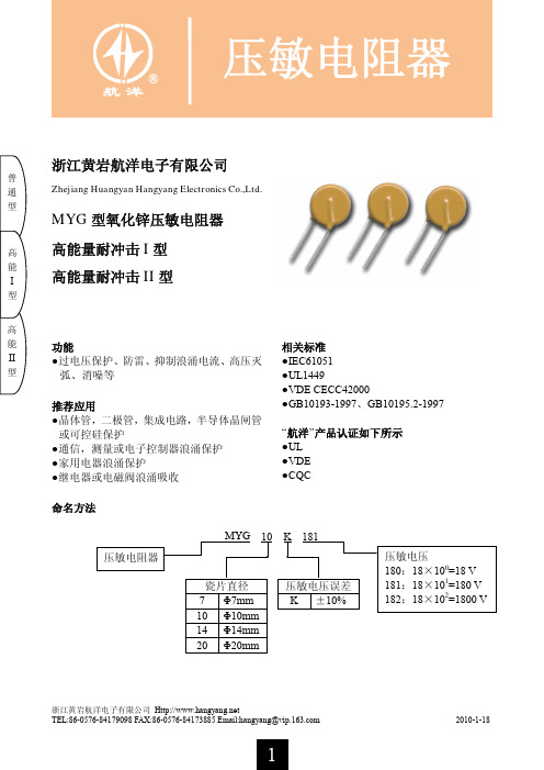
JMGPM 25 M9BW 30 通用接线器型号说明文档说明书

JMGPM 25M9BW30Port thread typeNil M thread ø12 to ø32Rc ø40 to ø100TN NPT TFGTypeSpecial functionElectrical entryI n d i c a t o r l i g h tWiring (Output)Load voltage Auto switch model Lead wire length [m]Pre-wiredconnector Applicable load DCACPerpendicularIn-line0.5(Nil)1(M)3(L)5(Z)S o l i d s t a t e a u t o s w i t c h———Grommet Yes 3-wire (NPN)24 V5 V, 12 V —M9NV M9N V V V v v IC circuit Relay, PLC3-wire (PNP)M9PV M9P V V V v v 2-wire12 V M9BV M9B V V V v v —Diagnostic indication (2-color indicator)3-wire (NPN)5 V, 12 V M9NWV M9NW V V V v v IC circuit 3-wire (PNP)M9PWV M9PW V V V v v 2-wire 12 V M9BWV M9BW V V V v v —Water resistant (2-color indicator)3-wire (NPN) 5 V, 12 V M9NAV ∗∗M9NA ∗∗v v V v v IC circuit 3-wire (PNP)M9PAV ∗∗M9PA ∗∗v v V v v 2-wire12 VM9BAV ∗∗M9BA ∗∗vvVvv—Applicable Auto Switches /Refer to the WEB catalog or Best Pneumatics for further information on auto switches.∗ Lead wire length symbols: 0.5 m………… N il (Example) M9NW 1 m………… M (Example) M9NWM 3 m………… L (Example) M9NWL 5 m………… Z (Example) M9NWZ∗ For details about auto switches with pre-wired connector, refer to the WEB catalog or Best Pneumatics.∗ Auto switches are shipped together, (but not assembled).∗ Solid state auto switches marked with “v ” are produced upon receipt of order.∗∗ Water resistant type auto switches can be mounted on the above models, but in such case SMC cannot guarantee water resistance.Please contact SMC regarding water resistant types with the above model numbers.How to OrderCylinder stroke [mm]Refer to “Standard Strokes” on page 4.Bearing type MSlide bearingBore size1210 mm x 21612 mm x 22016 mm x 22520 mm x 23225 mm x 24032 mm x 25040 mm x 26345 mm x 28056 mm x 210071 mm x 2Auto switchNilWithout auto switch (Built-in magnet)∗ For applicable auto switches, refer to the table below.Number of auto switchesNil 2S 1nnCompactGuide CylinderJMGP Seriesø12, ø16, ø20, ø25, ø32, ø40, ø50, ø63, ø80, ø1003Standard StrokesOUTIN[N]Bore size [mm]Rod size [mm]Operating directionPiston area[mm 2]Operating pressure [MPa]0.20.30.40.50.60.7ø12(ø10 x 2)6OUT 1573147637994110IN 101203040506070ø16(ø12 x 2)6OUT 226456890113136158IN 17034516885102119ø20(ø16 x 2)8OUT 40280121161201241281IN 3026090121151181211ø25(ø20 x 2)10OUT 628126188251314377440IN 47194141188236283330ø32(ø25 x 2)12OUT 982196295393491589687IN 756151227302378453529ø40(ø32 x 2)16OUT 16083224836438049651126IN 1206241362483603724844ø50(ø40 x 2)18OUT 25135037541005125715081759IN 2004401601802100212031403ø63(ø45 x 2)20OUT 31816369541272159019092227IN 25535117661021127615321787ø80(ø56 x 2)25OUT 492698514781970246329563448IN 394478911831578197223672761ø100(ø71 x 2)30OUT 7918158423763167395947515543IN 6505130119512602325239034553Note) Theoretical output [N] = Pressure [MPa] x Piston area [mm 2]Theoretical OutputSpecificationsBore size [mm]Standard stroke [mm]ø12 (ø10 x 2)ø16 (ø12 x 2)10, 20, 30, 50, 100ø20 (ø16 x 2)ø25 (ø20 x 2)20, 30, 50, 100, 150ø32 (ø25 x 2)ø40 (ø32 x 2)ø50 (ø40 x 2)ø63 (ø45 x 2)ø80 (ø56 x 2)ø100 (ø71 x 2)25, 50, 100, 150, 200∗ Intermediate strokes are available as a special order.Bore size [mm]ø12(ø10 x 2)ø16(ø12 x 2)ø20(ø16 x 2)ø25(ø20 x 2)ø32(ø25 x 2)ø40(ø32 x 2)ø50(ø40 x 2)ø63(ø45 x 2)ø80(ø56 x 2)ø100(ø71 x 2)Action Double actingFluidAir Proof pressure1.05 MPa Maximum operating pressure 0.7 MPa ∗1Minimum operating pressure 0.15 MPa Ambient and fluid temperature 5 to 60°CPiston speed Note)∗50 to 300 mm/s ∗150 to 250 mm/s ∗1Cushion Rubber bumper on both ends LubricationNot required (Non-lube)Stroke length tolerance+1.50mmNote) Maximum speed with no load∗ Depending on the system configuration selected, the specified speed may not be satisfied.∗1 Maximum operating pressure and piston speed are different from the current product (MGP series).[kg]Bore size [mm]Stroke [mm]1020253050100150200ø12 (ø10 x 2)0.090.12—0.140.190.30——ø16 (ø12 x 2)0.100.13—0.150.200.32——ø20 (ø16 x 2)—0.21—0.250.330.530.72—ø25 (ø20 x 2)—0.28—0.330.430.680.92—ø32 (ø25 x 2)——0.60—0.77 1.11 1.44 1.78ø40 (ø32 x 2)——0.80— 1.07 1.62 2.16 2.70ø50 (ø40 x 2)—— 1.27— 1.63 2.36 3.09 3.82ø63 (ø45 x 2)—— 1.60— 2.03 2.89 3.74 4.60ø80 (ø56 x 2)—— 2.81— 3.47 4.79 6.127.44ø100 (ø71 x 2)——4.48— 5.407.229.0510.87WeightSymbolRubber bumperRefer to pages 10 and 11 for cylinders with auto switches.·Auto switch proper mounting position (detection at stroke end) and mounting height·Minimum stroke for auto switch mounting ·Operating range·Auto switch mounting4Compact Guide CylinderJMGP Series。
MAX4130EUK+T,MAX4130EUK+T,MAX4132ESA+,MAX4132EUA+,MAX4131ESA,MAX4131EBT+T, 规格书,Datasheet 资料

MAX4130–MAX4134________________________________________________________________Maxim Integrated Products1For pricing, delivery, and ordering information,please contact Maxim/Dallas Direct!at 1-888-629-4642, or visit Maxim’s website at .General DescriptionThe MAX4130–MAX4134 family of operational amplifiers combines 10MHz gain-bandwidth product and excellent DC accuracy with Rail-to-Rail ®operation at the inputs and outputs. These devices require only 900µA per amplifier, and operate from either a single supply (+2.7V to +6.5V) or dual supplies (±1.35V to ±3.25V) with a common-mode voltage range that extends 250mV beyond V EE and V CC . They are capable of driving 250Ωloads and are unity-gain stable. In addition, the MAX4131/ MAX4133 feature a shutdown mode in which the outputs are placed in a high-impedance state and the supply current is reduced to only 25µA per amplifier.With their rail-to-rail input common-mode range and output swing, the MAX4130–MAX4134 are ideal for low-voltage, single-supply operation. Although the minimum operating voltage is specified at 2.7V, the devices typically operate down to 1.8V. In addition, low offset voltage and high speed make them the ideal signal-conditioning stages for precision, low-voltage data-acquisition systems. The MAX4130 is offered in the space-saving 5-pin SOT23 package. The MAX4131 is offered in the ultra-small 6-bump, 1mm x 1.5mm chip-scale package (UCSP™).________________________ApplicationsBattery-Powered Instruments Portable Equipment Data-Acquisition Systems Signal ConditioningLow-Power, Low-Voltage ApplicationsFeatureso 6-Bump UCSP (MAX4131)o +2.7V to +6.5V Single-Supply Operationo Rail-to-Rail Input Common-Mode Voltage Rangeo Rail-to-Rail Output Voltage Swing o 10MHz Gain-Bandwidth Product o 900µA Quiescent Current per Amplifier o 25µA Shutdown Function (MAX4131/MAX4133)o 200µV Offset Voltageo No Phase Reversal for Overdriven Inputs o Drive 250ΩLoadso Stable with 160pF Capacitive Loads o Unity-Gain StableSingle/Dual/Quad, Wide-Bandwidth, Low-Power,Single-Supply, Rail-to-Rail I/O Op Amps19-1089; Rev 3; 3/03*Dice are specified at T A = +25°C. DC parameters only.Ordering Information continued at end of data sheet.Pin Configurations appear at end of data sheet.Rail-to-Rail is a registered trademark of Nippon Motorola, Ltd.UCSP is a trademark of Maxim Integrated Products, Inc.M A X 4130–M A X 4134Single/Dual/Quad, Wide-Bandwidth, Low-Power,Single-Supply Rail-to-Rail I/O Op Amps 2_______________________________________________________________________________________ABSOLUTE MAXIMUM RATINGSDC ELECTRICAL CHARACTERISTICS(V CC = +2.7V to +6.5V, V EE = 0V, V CM = 0V, V OUT = V CC /2, R L tied to V CC /2, SHDN ≥2V (or open), T A = +25°C , unless otherwise noted.)Stresses beyond those listed under “Absolute Maximum Ratings” may cause permanent damage to the device. These are stress ratings only, and functional operation of the device at these or any other conditions beyond those indicated in the operational sections of the specifications is not implied. Exposure to absolute maximum rating conditions for extended periods may affect device reliability.Supply Voltage (V CC - V EE )...................................................7.5V IN+, IN-, SHDN Voltage...................(V CC + 0.3V) to (V EE - 0.3V)Output Short-Circuit Duration (Note 1).......................Continuous(short to either supply)Continuous Power Dissipation (T A = +70°C)5-Pin SOT23 (derate 7.1mW/°C above +70°C)............571mW 6-Bump UCSP (derate 2.9mW/°C above +70°C).........308mW 8-Pin SO (derate 5.88mW/°C above +70°C)................471mW8-Pin µMAX (derate 4.10mW/°C above +70°C)...........330mW 14-Pin SO (derate 8.00mW/°C above +70°C)..............640mW Operating Temperature RangeMAX413_E__...................................................-40°C to +85°C Maximum Junction Temperature.....................................+150°C Storage Temperature Range.............................-65°C to +160°C Lead Temperature (soldering, 10s).................................+300°C Bump Reflow Temperature .........................................+235°CNote 1:Provided that the maximum package power-dissipation rating is not exceeded.MAX4130–MAX4134Single/Dual/Quad, Wide-Bandwidth, Low-Power,Single-Supply Rail-to-Rail I/O Op AmpsDC ELECTRICAL CHARACTERISTICS (continued)(V CC = +2.7V to +6.5V, V EE = 0V, V CM = 0V, V OUT = V CC /2, R L tied to V CC /2, SHDN ≥2V (or open), T A = +25°C , unless otherwise noted.)DC ELECTRICAL CHARACTERISTICS(V CC = +2.7V to +6.5V, V EE = 0V, V CM = 0V, V OUT = V CC /2, R L tied to V CC /2, SHDN ≥2V (or open), T A = -40°C to +85°C , unlessM A X 4130–M A X 4134Single/Dual/Quad, Wide-Bandwidth, Low-Power,Single-Supply Rail-to-Rail I/O Op Amps 4_______________________________________________________________________________________DC ELECTRICAL CHARACTERISTICS(V CC = +2.7V to +6.5V, V EE = 0V, V CM = 0V, V OUT = V CC /2, R L tied to V CC /2, SHDN ≥2V (or open), T A = -40°C to +85°C , unlessMAX4130–MAX4134Single/Dual/Quad, Wide-Bandwidth, Low-Power,Single-Supply Rail-to-Rail I/O Op Amps_______________________________________________________________________________________5DC ELECTRICAL CHARACTERISTICS (continued)(V CC = +2.7V to +6.5V, V EE = 0V, V CM = 0V, V OUT = V CC /2, R L tied to V CC /2, SHDN ≥2V (or open), T A = -40°C to +85°C , unless otherwise noted.) (Note 2)AC ELECTRICAL CHARACTERISTICSM A X 4130–M A X 4134Single/Dual/Quad, Wide-Bandwidth, Low-Power,Single-Supply, Rail-to-Rail I/O Op Amps 6_______________________________________________________________________________________60-401001k 10k 1M 10M100k 100M GAIN AND PHASE vs. FREQUENCY-20FREQUENCY (Hz)G A I N (d B )02040P H A S E (D E G R E E S )180144720-72-144-180-108-363610860-401001k 10k 1M 10M100k 100MGAIN AND PHASEvs. FREQUENCY (WITH C)-20FREQUENCY (Hz)G A I N (d B )2040P H A S E (D E G R E E S )180144720-72-144-180-108-36361080-100101001k100k1M10M10k 100MPOWER-SUPPLY REJECTIONvs. FREQUENCY-80FREQUENCY (Hz)P S R (d B )-60-40-2001051520253530454050-40-25-105203550658095SHUTDOWN SUPPLY CURRENTvs. TEMPERATURETEMPERATURE (°C)S U P P L Y C U R R E N T (µA )1000.100.011001k100k1M10M10k100MOUTPUT IMPEDANCE vs. FREQUENCYFREQUENCY (Hz)O U T P U T I M P E D A N C E (Ω)1101150800850900950105010001100-40-25-105203550658095SUPPLY CURRENT PER AMPLIFIERvs. TEMPERATURETEMPERATURE (°C)S U P P L Y C U R R E N T (µA )-10-505101520-40-25-105203550658095OUTPUT LEAKAGE CURRENTvs. TEMPERATURETEMPERATURE (°C)L E A K A G E C U R R E N T (µA )Typical Operating Characteristics(V CC = +5V, V EE = 0V, VCM = V CC / 2, T A = +25°C, unless otherwise noted.)-600123456INPUT BIAS CURRENT vs. COMMON-MODE VOLTAGECOMMON-MODE VOLTAGE (V)I N P U T B I A S C U R R E N T (n A )-50-40-30-20-10010203040-60-40-40-25-105203550658095INPUT BIAS CURRENTvs. TEMPERATURETEMPERATURE (°C)I N P U T B I A S C U R R E N T (n A )-200204060MAX4130–MAX4134Single/Dual/Quad, Wide-Bandwidth, Low-Power,Single-Supply, Rail-to-Rail I/O Op Amps_______________________________________________________________________________________712070750600110115OUTPUT VOLTAGE: EITHER SUPPLY (mV)G A I N (d B )30095859080100200500105100400LARGE-SIGNAL GAIN vs. OUTPUT VOLTAGE130-40-25-105203550658095LARGE-SIGNAL GAIN vs. TEMPERATURE90120TEMPERATURE (°C)G A I N (d B )11010085951251151051.21.31.51.41.61.71.81.9-40-25-105203550658095MINIMUM OPERATING VOLTAGEvs. TEMPERATUREM A X 4130/34-21TEMPERATURE (°C)M I N I M U M O P E R A T I N G V O L T A G E (V )Typical Operating Characteristics (continued)(V CC = +5V, V EE = 0V, V CM = V CC / 2, T A = +25°C, unless otherwise noted.)12080859095100105110115-40-25-105203550658095COMMON-MODE REJECTIONvs. TEMPERATURETEMPERATURE (°C)C O M M O N -M ODE R E J E C T I O N (d B )130700600120OUTPUT VOLTAGE: EITHER SUPPLY (mV)G A I N (dB )3001009080100200500110400LARGE-SIGNAL GAIN vs. OUTPUT VOLTAGE12060600110OUTPUT VOLTAGE: EITHER SUPPLY (mV)G A I N (d B )300908070100200500100400LARGE-SIGNAL GAIN vs. OUTPUT VOLTAGE12080-40-25-105203550658095LARGE-SIGNAL GAIN vs. TEMPERATURE90TEMPERATURE (°C)G A I N (d B )105859511511010012070750600110115OUTPUT VOLTAGE: EITHER SUPPLY (mV)G A I N (d B )30095859080100200500105100400LARGE-SIGNAL GAIN vs. OUTPUT VOLTAGE-3.00-2.25-0.75-1.5001.500.752.253.00-40-25-105203550658095INPUT OFFSET VOLTAGE vs. TEMPERATURETEMPERATURE (°C)V O L T A G E (m V )M A X 4130–M A X 4134Single/Dual/Quad, Wide-Bandwidth, Low-Power,Single-Supply, Rail-to-Rail I/O Op Amps 8_______________________________________________________________________________________1408010k 1k 100k 10M 1M CHANNEL SEPARATION vs. FREQUENCYFREQUENCY (Hz)C H A N N E L S E P A R A T I O N (d B )1009013011012010100k10kFREQUENCY (Hz)1001k 0.03000.0050.0100.0150.0200.025 TOTAL HARMONIC DISTORTION AND NOISE vs. FREQUENCYT H D A N D N O I S E (%)0.10.0014.04.44.25.04.84.6TOTAL HARMONIC DISTORTION AND NOISE vs. PEAK-TO-PEAK SIGNAL AMPLITUDEPEAK-TO-PEAK SIGNAL AMPLITUDE (V)T H D + N O I S E (%)0.01INTIME (200ns/div)V O L T A G E (50m V /d i v )OUTMAX4131SMALL-SIGNAL TRANSIENT RESPONSE (NONINVERTING)IN TIME (200ns/div)V O L T A G E (50m V /d i v )OUT MAX4131SMALL-SIGNAL TRANSIENT RESPONSE (INVERTING)A V = -1IN TIME (2µs/div)V O L T A G E (2V/d i v )OUT MAX4131LARGE-SIGNAL TRANSIENT RESPONSE (NONINVERTING)A V = +1INTIME (2µs/div)V O L T A G E (2V /d i v )OUTMAX4131LARGE-SIGNAL TRANSIENT RESPONSE (INVERTING)Typical Operating Characteristics (continued)(V CC = +5V, V EE = 0V, V CM = V CC / 2, T A = +25°C, unless otherwise noted.)1600-40-25-105203550658095MINIMUM OUTPUT VOLTAGEvs. TEMPERATURE20140120TEMPERATURE (°C)V O U T - V E E (m V )100806040050100150200250300-40-25-105203550658095MAXIMUM OUTPUT VOLTAGEvs. TEMPERATURETEMPERATURE (°C)V C C - V O U T (m V )MAX4130–MAX4134Single/Dual/Quad, Wide-Bandwidth, Low-Power,Single-Supply, Rail-to-Rail I/O Op Amps_______________________________________________________________________________________9Figure 1a. Reducing Offset Error Due to Bias Current (Noninverting)Figure 1b. Reducing Offset Error Due to Bias Current (Inverting)M A X 4130–M A X 4134Single/Dual/Quad, Wide-Bandwidth, Low-Power,Single-Supply, Rail-to-Rail I/O Op Amps 10______________________________________________________________________________________Applications InformationRail-to-Rail Input StageDevices in the MAX4130–MAX4134 family of high-speed amplifiers have rail-to-rail input and output stages designed for low-voltage, single-supply opera-tion. The input stage consists of separate NPN and PNP differential stages that combine to provide an input common-mode range that extends 0.2V beyond the supply rails. The PNP stage is active for input volt-ages close to the negative rail, and the NPN stage is active for input voltages near the positive rail. The input offset voltage is typically below 200µV. The switchover transition region, which occurs near V CC / 2, has been extended to minimize the slight degradation in com-mon-mode rejection ratio caused by the mismatch of the input pairs. Their low offset voltage, high band-width, and rail-to-rail common-mode range make these op amps excellent choices for precision, low-voltage data-acquisition systems.Since the input stage switches between the NPN and PNP pairs, the input bias current changes polarity as the input voltage passes through the transition region.Reduce the offset error caused by input bias currents flowing through external source impedances by match-ing the effective impedance seen by each input (Figures 1a, 1b). High source impedances, together with input capacitance, can create a parasitic pole that produces an underdamped signal response. Reducing the input impedance or placing a small (2pF to 10pF)capacitor across the feedback resistor improves response.The MAX4130–MAX4134s ’ inputs are protected from large differential input voltages by 1k Ωseries resistors and back-to-back triple diodes across the inputs (Figure 2). For differential input voltages less than 1.8V,input resistance is typically 500k Ω. For differential input voltages greater than 1.8V, input resistance is approxi-mately 2k Ω. The input bias current is given by the fol-lowing equation:Figure 2. Input Protection CircuitMAX4130–MAX4134Single/Dual/Quad, Wide-Bandwidth, Low-Power,Single-Supply, Rail-to-Rail I/O Op Amps______________________________________________________________________________________11Rail-to-Rail Output StageThe minimum output voltage is within millivolts of ground for single-supply operation where the load is referenced to ground (V EE ). Figure 3 shows the input voltage range and output voltage swing of a MAX4131connected as a voltage follower. With a +3V supply and the load tied to ground, the output swings from 0.00V to 2.90V. The maximum output voltage swing depends on the load, but will be within 150mV of a +3V supply, even with the maximum load (500Ωto ground).Driving a capacitive load can cause instability in most high-speed op amps, especially those with low quies-cent current. The MAX4130–MAX4134 have a high tol-erance for capacitive loads. They are stable with capacitive loads up to 160pF. Figure 4 gives the stable operating region for capacitive loads. Figures 5 and 6show the response with capacitive loads and the results of adding an isolation resistor in series with the output (Figure 7). The resistor improves the circuit ’s phase margin by isolating the load capacitor from the op amp ’s output.INTIME (1µs/div)V O L T A G E (1V /d i v )OUTV CC = 3V, R L = 10k Ω to V EEFigure 3. Rail-to-Rail Input/Output Voltage RangeFigure 4. Capacitive-Load StabilityINTIME (200ns/div)V O L T A G E (50m V /d i v )OUTV CC = 5V R L = 10k Ω C L = 130pFFigure 5. MAX4131 Small-Signal Transient Response with Capacitive Load Figure 6. MAX4131 Transient Response to Capacitive Load with Isolation ResistorINTIME (500ns/div)V O L T A G E (50m V /d i v )OUTV CC = 5V C L = 1000pF R S = 39ΩM A X 4130–M A X 4134Single/Dual/Quad, Wide-Bandwidth, Low-Power,Single-Supply, Rail-to-Rail I/O Op Amps 12______________________________________________________________________________________Power-Up and Shutdown ModeThe MAX4130–MAX4134 amplifiers typically settle with-in 1µs after power-up. Figures 9 and 10 show the out-put voltage and supply current on power-up, using the test circuit of Figure 8.The MAX4131 and MAX4133 have a shutdown option.When the shutdown pin (SHDN ) is pulled low, the sup-ply current drops below 25µA per amplifier and theamplifiers are disabled with the outputs in a high-impedance state. Pulling SHDN high or leaving it float-ing enables the amplifier. In the dual-amplifier MAX4133, the shutdown functions operate indepen-dently. Figures 11 and 12 show the output voltage and supply current responses of the MAX4131 to a shut-down pulse, using the test circuit of Figure 8.Figure 7. Capacitive-Load Driving CircuitFigure 8. Power-Up/Shutdown Test CircuitV CC TIME (5µs/div)V O L T A G E (1V /d i v )OUTFigure 9. Power-Up Output Voltage V CC (1V/div)TIME (5µs/div)I EE(500µA/div)Figure 10. Power-Up Supply CurrentMAX4130–MAX4134Single/Dual/Quad, Wide-Bandwidth, Low-Power,Single-Supply, Rail-to-Rail I/O Op Amps______________________________________________________________________________________13Power Supplies and LayoutThe MAX4130–MAX4134 operate from a single +2.7V to +6.5V power supply, or from dual supplies of ±1.35V to ±3.25V. For single-supply operation, bypass the power supply with a 0.1µF ceramic capacitor in parallel with at least 1µF. For dual supplies, bypass each sup-ply to ground.Good layout improves performance by decreasing the amount of stray capacitance at the op amp ’s inputs and outputs. Decrease stray capacitance by placing external components close to the op amp ’s pins, mini-mizing trace lengths and resistor leads.UCSP Applications InformationFor the latest application details on UCSP construction,dimensions, tape carrier information, PC board tech-niques, bump-pad layout, and the recommended reflow temperature profile, as well as the latest informa-tion on reliability testing results, go to Maxim ’s website at /ucsp and search for the Application Note: UCSP –A Wafer-Level Chip-Scale Package .TIME (1µs/div)OUTFigure 11. Shutdown Output Voltage TIME (1µs/div)Figure 12. Shutdown Enable/Disable Supply CurrentM A X 4130–M A X 4134Single/Dual/Quad, Wide-Bandwidth, Low-Power,Single-Supply, Rail-to-Rail I/O Op Amps 14________________________________________________________________________________________________________________________________________________Pin ConfigurationsMAX4130–MAX4134Single/Dual/Quad, Wide-Bandwidth, Low-Power,Single-Supply, Rail-to-Rail I/O Op Amps______________________________________________________________________________________15Chip InformationOrdering Information (continued)MAX4130 TRANSISTOR COUNT: 170MAX4131 TRANSISTOR COUNT: 170MAX4132 TRANSISTOR COUNT: 340MAX4134 TRANSISTOR COUNT: 680*Dice are specified at T A = +25°C, DC parameters only.Package Information(The package drawing(s) in this data sheet may not reflect the most current specifications. For the latest package outline information,go to /packages .)M A X 4130–M A X 4134Single/Dual/Quad, Wide-Bandwidth, Low-Power,Single-Supply, Rail-to-Rail I/O Op Amps 16______________________________________________________________________________________Package Information (continued)(The package drawing(s) in this data sheet may not reflect the most current specifications. For the latest package outline information,go to /packages .)MAX4130–MAX4134Single/Dual/Quad, Wide-Bandwidth, Low-Power,Single-Supply, Rail-to-Rail I/O Op Amps______________________________________________________________________________________17Package Information (continued)(The package drawing(s) in this data sheet may not reflect the most current specifications. For the latest package outline information,go to /packages .)Maxim cannot assume responsibility for use of any circuitry other than circuitry entirely embodied in a Maxim product. No circuit patent licenses are M A X 4130–M A X 4134Single/Dual/Quad, Wide-Bandwidth, Low-Power,Single-Supply, Rail-to-Rail I/O Op Amps implied. Maxim reserves the right to change the circuitry and specifications without notice at any time.18__________________Maxim Integrated Products, 120 San Gabriel Drive, Sunnyvale, CA 94086 (408) 737-7600©2003 Maxim Integrated ProductsPrinted USAis a registered trademark of Maxim Integrated Products.Package Information (continued)(The package drawing(s) in this data sheet may not reflect the most current specifications. For the latest package outline information,go to /packages .)。
常用三极管参数大全

玉林万顺达电脑芯片级维修资料 2010-07-20整理玉林万顺达电脑芯片级维修资料 2010-07-20整理玉林万顺达电脑芯片级维修资料 2010-07-20整理玉林万顺达电脑芯片级维修资料 2010-07-20整理玉林万顺达电脑芯片级维修资料 2010-07-20整理玉林万顺达电脑芯片级维修资料 2010-07-20整理玉林万顺达电脑芯片级维修资料 2010-07-20整理玉林万顺达电脑芯片级维修资料 2010-07-20整理玉林万顺达电脑芯片级维修资料 2010-07-20整理玉林万顺达电脑芯片级维修资料 2010-07-20整理玉林万顺达电脑芯片级维修资料 2010-07-20整理玉林万顺达电脑芯片级维修资料 2010-07-20整理玉林万顺达电脑芯片级维修资料 2010-07-20整理玉林万顺达电脑芯片级维修资料 2010-07-20整理玉林万顺达电脑芯片级维修资料 2010-07-20整理玉林万顺达电脑芯片级维修资料 2010-07-20整理玉林万顺达电脑芯片级维修资料 2010-07-20整理玉林万顺达电脑芯片级维修资料 2010-07-20整理玉林万顺达电脑芯片级维修资料 2010-07-20整理玉林万顺达电脑芯片级维修资料 2010-07-20整理玉林万顺达电脑芯片级维修资料 2010-07-20整理玉林万顺达电脑芯片级维修资料 2010-07-20整理玉林万顺达电脑芯片级维修资料 2010-07-20整理玉林万顺达电脑芯片级维修资料 2010-07-20整理玉林万顺达电脑芯片级维修资料 2010-07-20整理玉林万顺达电脑芯片级维修资料 2010-07-20整理玉林万顺达电脑芯片级维修资料 2010-07-20整理玉林万顺达电脑芯片级维修资料 2010-07-20整理玉林万顺达电脑芯片级维修资料 2010-07-20整理玉林万顺达电脑芯片级维修资料 2010-07-20整理。
H9DA1GG25HAMBR_Series_(Rev 1.2)

NC
DQ0
VDD
VSSn
VCC
NC
1Gb (128Mb X8) NAND FLASH B-Die
Rev 1.2 / Dec. 2011
8
H9DA1GG25HAMBR series NAND 1Gb(x8) / mobile DDR 256Mb(x16)
1. SUMMARY DESCRIPTION
The Hynix NAND Flash is a 128 M x 8 bit with spare 4 M x 8 bit capacity. The device is offered in 1.8 V Vcc Power Supply, and with x8 I/O interface. Its NAND cell provides the most cost-effective solution for the solid state mass storage market. The memory is divided into blocks that can be erased independently so it is possible to preserve valid data while old data is erased. The device contains 1024 blocks, composed by 64 pages. A program operation allows to write the 2112 byte page in typical 200 us and an erase operation can be performed in typical 2.0 ms on a 128 K byte block. Data in the page can be read out at 45 ns cycle time per byte. The I/O pins serve as the ports for address and data input/output as well as command input. This interface allows a reduced pin count and easy migration towards different densities, without any rearrangement of footprint. Commands, Data and Addresses are synchronously introduced using CE, WE, RE ALE and CLE input pin. The on-chip Program/Erase Controller automates all program and erase functions including pulse repetition, where required, and internal verification and margining of data. The modify operations can be locked using the WP input. The chip supports CE don't care function. This function allows the direct download of the code from the NAND Flash memory device by a microcontroller, since the CE transitions do not stop the read operation. The output pin R/B (open drain buffer) signals the status of the device during each operation. In a system with multiple memories the R/B pins can be connected all together to provide a global status signal. Even the write-intensive systems can take advantage of the H27S1G8F2B Series extended reliability of 100 K program/ erase cycles by providing ECC (Error Correcting Code) with real time mapping-out algorithm. The copy back function allows the optimization of defective blocks management: when a page program operation fails the data can be directly programmed in another page inside the same array section without the time consuming serial data insertion phase. Data read out after copy back read is allowed. This device includes also extra features like OTP/Unique ID area, Read ID2 extension.
MYG压敏电阻
395
84
8000 6000
30
14K271 270 243-297 175 225
455
99
8000 6000
30
高
14K331 330 297-363 210 275
550
115
8000 6000
30
能
14K361 360 324-396 230 300
595
130
8000 6000
30
I
14K391 390 351-429 250 320
1025
92
4600
3500
10K681 680 612-748 420 560
1120
92
4600
3500
10K751 750 675-825 460 615
1240
100
4600
3500
10K821 820 738-902 510 670
1355
110
4600
3500
浙江黄岩航洋电子有限公司 TEL:86-0576-84179098 FAX:86-0576-84173885 Email:hangyang@
300
15.6
2300
1750
通
07K201 200 185-225 130 170
340
17.5
2300
1750
型
07K221 220 198-242 140 180
360
19
2300
1750
07K241 240 216-264 150 200
395
21
2300
1750
07K271 270 243-297 175 225
MMSZ4xxxT1G系列和SZMMSZ4xxxT1G系列零点电阻电源器件的商品说明书

MMSZ4686T1G MMSZ4686T1G.MMSZ4xxxT1G Series, SZMMSZ4xxxT1G Series Zener Voltage Regulators 500 mW, Low I ZT SOD−123 Surface MountThree complete series of Zener diodes are offered in the convenient, surface mount plastic SOD−123 package. These devices provide a convenient alternative to the leadless 34−package style.Features•500 mW Rating on FR−4 or FR−5 Board•Wide Zener Reverse V oltage Range − 1.8 V to 43 V•Low Reverse Current (I ZT) − 50 m A•Package Designed for Optimal Automated Board Assembly •Small Package Size for High Density Applications•ESD Rating of Class 3 (>16 kV) per Human Body Model•SZ Prefix for Automotive and Other Applications Requiring Unique Site and Control Change Requirements; AEC−Q101 Qualified and PPAP Capable•These Devices are Pb−Free and are RoHS Compliant*Mechanical Characteristics:CASE:V oid-free, transfer-molded, thermosetting plastic case FINISH:Corrosion resistant finish, easily solderableMAXIMUM CASE TEMPERATURE FOR SOLDERING PURPOSES: 260°C for 10 SecondsPOLARITY:Cathode indicated by polarity band FLAMMABILITY RATING:UL 94 V−0MAXIMUM RATINGSRating Symbol Max Units Total Power Dissipation on FR−5 Board,(Note 1) @ T L = 75°CDerated above 75°C P D5006.7mWmW/°CThermal Resistance, (Note 2) Junction−to−Ambient R q JA340°C/WThermal Resistance, (Note 2) Junction−to−Lead R q JL150°C/WJunction and Storage Temperature Range T J, T stg−55 to+150°CStresses exceeding those listed in the Maximum Ratings table may damage the device. If any of these limits are exceeded, device functionality should not be assumed, damage may occur and reliability may be affected.1.FR−5 = 3.5 X 1.5 inches, using the minimum recommended footprint.2.Thermal Resistance measurement obtained via infrared Scan Method.*For additional information on our Pb−Free strategy and soldering details, please download the ON Semiconductor Soldering and Mounting Techniques Reference Manual, SOLDERRM/D.Cathode AnodeSee specific marking information in the device marking column of the Electrical Characteristics table on page 3 of this data sheet.DEVICE MARKING INFORMATIONSOD−123CASE 425STYLE 1Device Package Shipping†ORDERING INFORMATIONMARKING DIAGRAM†For information on tape and reel specifications, including part orientation and tape sizes, please refer to our T ape and Reel Packaging Specifications Brochure, BRD8011/D.MMSZ4xxxT1G SOD−123(Pb−Free)3,000 /Tape & ReelMMSZ4xxxT3G SOD−123(Pb−Free)10,000 /Tape & Reel xx= Device Code (Refer to page 3)M= Date CodeG= Pb−Free Package(Note: Microdot may be in either location)1SZMMSZ4xxxT1G SOD−123(Pb−Free)3,000 /Tape & ReelSZMMSZ4xxxT3G SOD−123(Pb−Free)10,000 /Tape & ReelELECTRICAL CHARACTERISTICS (T A = 25°C unless otherwise noted, V F = 0.9 V Max. @ I F = 10 mA)Symbol ParameterV Z Reverse Zener Voltage @ I ZTI ZT Reverse CurrentI R Reverse Leakage Current @ V RVR Reverse VoltageI F Forward CurrentV F Forward Voltage @ I FProduct parametric performance is indicated in the Electrical Characteristics for the listed test conditions, unless otherwise noted. Product performance may not be indicated by the Electrical Characteristics if operated under different conditions.ELECTRICAL CHARACTERISTICS (T A = 25°C unless otherwise noted, V F = 0.9 V Max. @ I F = 10 mA)Device*DeviceMarkingZener Voltage (Note 3)Leakage CurrentV Z (Volts)@ I ZT I R @ V RMin Nom Max m A m A VoltsMMSZ4678T1G CC 1.71 1.8 1.89507.51 MMSZ4679T1G CD 1.90 2.0 2.105051 MMSZ4680T1G CE 2.09 2.2 2.315041 MMSZ4681T1G CF 2.28 2.4 2.525021 MMSZ4682T1G CH 2.565 2.7 2.8355011 MMSZ4683T1G CJ 2.85 3.0 3.15500.81 MMSZ4684T1G CK 3.13 3.3 3.47507.5 1.5 MMSZ4685T1G CM 3.42 3.6 3.78507.52 MMSZ4686T1G CN 3.70 3.9 4.105052 MMSZ4687T1G CP 4.09 4.3 4.525042 SZMMSZ4687T1G CG6 4.09 4.3 4.525042 MMSZ4688T1G CT 4.47 4.7 4.9450103 MMSZ4689T1G CU 4.85 5.1 5.3650103 MMSZ4690T1G/T3G CV 5.32 5.6 5.8850104 MMSZ4691T1G CA 5.89 6.2 6.5150105 MMSZ4692T1G CX 6.46 6.87.145010 5.1 MMSZ4693T1G CY7.137.57.885010 5.7 MMSZ4694T1G CZ7.798.28.61501 6.2 MMSZ4695T1G DC8.278.79.14501 6.6 MMSZ4696T1G DD8.659.19.56501 6.9 MMSZ4697T1G DE9.501010.505017.6 MMSZ4698T1G DF10.451111.55500.058.4 MMSZ4699T1G DH11.401212.60500.059.1 MMSZ4700T1G DJ12.351313.65500.059.8 MMSZ4701T1G DK13.301414.70500.0510.6 MMSZ4702T1G DM14.251515.75500.0511.4 MMSZ4703T1G†DN15.201616.80500.0512.1 MMSZ4704T1G DP16.151717.85500.0512.9 MMSZ4705T1G DT17.101818.90500.0513.6 MMSZ4706T1G DU18.051919.95500.0514.4 MMSZ4707T1G DV19.002021.00500.0115.2 MMSZ4708T1G DA20.902223.10500.0116.7 MMSZ4709T1G DX22.802425.20500.0118.2 MMSZ4710T1G DY23.752526.25500.0119.0 MMSZ4711T1G†EA25.652728.35500.0120.4 MMSZ4712T1G EC26.602829.40500.0121.2 MMSZ4713T1G ED28.503031.50500.0122.8 MMSZ4714T1G EE31.353334.65500.0125.0 MMSZ4715T1G EF34.203637.80500.0127.3 MMSZ4716T1G EH37.053940.95500.0129.6 MMSZ4717T1G EJ40.854345.15500.0132.6 3.Nominal Zener voltage is measured with the device junction in thermal equilibrium at T L = 30°C ±1°C.*Include SZ-prefix devices where applicable.†MMSZ4703 and MMSZ4711 Not Available in 10,000/Tape & ReelTYPICAL CHARACTERISTICSV Z , T E M P E R A T U R E C O E F F I C I E N T (m V /C )°θV Z , NOMINAL ZENER VOLTAGE (V)Figure 1. Temperature Coefficients (Temperature Range −55°C to +150°C)V Z , T E M P E R A T U R E C O E F F I C I E N T (m V /C )°θ100101V Z , NOMINAL ZENER VOLTAGE (V)Figure 2. Temperature Coefficients (Temperature Range −55°C to +150°C)1.21.00.80.60.40.20T, TEMPERATURE (5C)Figure 3. Steady State Power Derating P p k, P E A K S U R G E P O W E R (W A T T S )PW, PULSE WIDTH (ms)Figure 4. Maximum Nonrepetitive Surge PowerP D , P O W E R D I S S I P A T I O N (W A T T S )V Z , NOMINAL ZENER VOLTAGEFigure 5. Effect of Zener Voltage onZener ImpedanceZ Z T , D Y N A M I C I M P E D A N C E ()ΩTYPICAL CHARACTERISTICSC , C A P A C I T A N C E (p F )V Z , NOMINAL ZENER VOLTAGE (V)Figure 6. Typical Capacitance 1000100101V Z , ZENER VOLTAGE (V)1001010.10.01I Z , Z EN E R C U R R E N T (m A )V Z , ZENER VOLTAGE (V)1001010.10.01I R , L E A K A G E C U R R E N T (A )μV Z , NOMINAL ZENER VOLTAGE (V)Figure 7. Typical Leakage Current10001001010.10.010.0010.00010.00001I Z , Z E N E R C U R R E N T (m A )Figure 8. Zener Voltage versus Zener Current(V Z Up to 12 V)Figure 9. Zener Voltage versus Zener Current(12 V to 91 V)SOD−123CASE 425−04ISSUE GDATE 07 OCT 2009SCALE 5:1NOTES:1.DIMENSIONING AND TOLERANCING PER ANSIY14.5M, 1982.2.CONTROLLING DIMENSION: INCH.DIM MIN NOM MAXMILLIMETERSINCHESA0.94 1.17 1.350.037A10.000.050.100.000b0.510.610.710.020c1.600.150.055D 1.40 1.80E 2.54 2.69 2.840.100---3.680.140L0.253.860.0100.0460.0020.0240.0630.1060.1450.0530.0040.0280.0710.1120.152MIN NOM MAX3.56H E---------0.006------------GENERICMARKING DIAGRAM**For additional information on our Pb−Free strategy and solderingdetails, please download the ON Semiconductor Soldering andMounting Techniques Reference Manual, SOLDERRM/D.SOLDERING FOOTPRINT**This information is generic. Please refer to device datasheet for actual part marking. Pb−Free indicator, “G” ormicrodot “ G”, may or may not be present.XXX= Specific Device CodeM= Date CodeG= Pb−Free Package1STYLE 1:PIN 1. CATHODE2. ANODE0.910.036ǒmminchesǓSCALE 10:1------q001010°°°°(Note: Microdot may be in either location) MECHANICAL CASE OUTLINEPACKAGE DIMENSIONSON Semiconductor and are trademarks of Semiconductor Components Industries, LLC dba ON Semiconductor or its subsidiaries in the United States and/or other countries.ON Semiconductor reserves the right to make changes without further notice to any products herein. ON Semiconductor makes no warranty, representation or guarantee regarding the suitability of its products for any particular purpose, nor does ON Semiconductor assume any liability arising out of the application or use of any product or circuit, and specifically disclaims any and all liability, including without limitation special, consequential or incidental damages. ON Semiconductor does not convey any license under its patent rights nor theON Semiconductor and are trademarks of Semiconductor Components Industries, LLC dba ON Semiconductor or its subsidiaries in the United States and/or other countries.ON Semiconductor owns the rights to a number of patents, trademarks, copyrights, trade secrets, and other intellectual property. A listing of ON Semiconductor’s product/patent coverage may be accessed at ON Semiconductor makes no warranty, representation or guarantee regarding the suitability of its products for any particular purpose, nor does ON Semiconductor assume any liability arising out of the application or use of any product or circuit, and specifically disclaims any and all liability, including without limitation special, consequential or incidental damages.PUBLICATION ORDERING INFORMATIONTECHNICAL SUPPORTNorth American Technical Support:Voice Mail: 1 800−282−9855 Toll Free USA/Canada Phone: 011 421 33 790 2910LITERATURE FULFILLMENT :Email Requests to:*******************ON Semiconductor Website: Europe, Middle East and Africa Technical Support:Phone: 00421 33 790 2910For additional information, please contact your local Sales RepresentativeMMSZ4686T1G MMSZ4686T1G.。