PM150CSE120中文资料
PM100RSD120资料
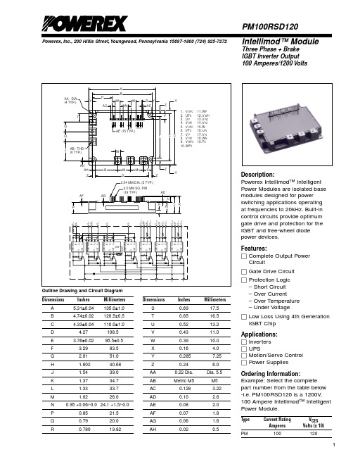
Powerex, Inc., 200 Hillis Street, Youngwood, Pennsylvania 15697-1800 (724) 925-7272Intellimod™ ModuleThree Phase + Brake IGBT Inverter Output 100 Amperes/1200 VoltsPM100RSD120Description:Powerex Intellimod™ Intelligent Power Modules are isolated base modules designed for power switching applications operating at frequencies to 20kHz. Built-in control circuits provide optimum gate drive and protection for the IGBT and free-wheel diode power devices.Features:□Complete Output Power Circuit□Gate Drive Circuit □Protection Logic –Short Circuit –Over Current–Over Temperature –Under Voltage□Low Loss Using 4th Generation IGBT Chip Applications:□Inverters □UPS□Motion/Servo Control □Power SuppliesOrdering Information:Example: Select the complete part number from the table below -i.e. PM100RSD120 is a 1200V ,100 Ampere Intellimod™ Intelligent Power Module.Type Current Rating V CES AmperesVolts (x 10)PM100120Outline Drawing and Circuit Diagram DimensionsInches Millimeters A 5.31±0.04135.0±1.0B 4.74±0.02120.5±0.5C 4.33±0.04110.0±1.0D 4.27108.5E 3.76±0.0295.5±0.5F 3.2983.5G 2.0151.0H 1.60240.68J 1.5439.0K 1.3734.7L 1.3333.7M 1.0226.0N 0.95 +0.06/-0.024.1 +1.5/-0.0P 0.8521.5Q 0.7920.0R0.78019.82DimensionsInches Millimeters S 0.6917.5T 0.6516.5U 0.5213.2V 0.4311.0W 0.39 10.0X 0.16 4.0Y 0.2857.25Z 0.24 6.0AA 0.22 Dia.Dia. 5.5AB Metric M5M5AC 0.128 3.22AD 0.10 2.6AE 0.08 2.0AF 0.07 1.8AG 0.06 1.6AH0.020.5PM100RSD120Intellimod™ ModuleThree Phase + Brake IGBT Inverter Output 100 Amperes/1200 VoltsPowerex, Inc., 200 Hillis Street, Youngwood, Pennsylvania 15697-1800 (724) 925-7272Absolute Maximum Ratings, T j = 25°C unless otherwise specifiedCharacteristicsSymbol PM100RSD120Units Power Device Junction T emperature T j -20 to 150°C Storage Temperature T stg -40 to 125°C Case Operating Temperature *T C -20 to 100°C Mounting Torque, M5 Mounting Screws —31in-lb Mounting Torque, M5 Main Terminal Screws —31in-lb Module Weight (Typical)—920Grams Supply Voltage Protected by OC and SCV CC(prot.)800Volts(V D = 13.5 - 16.5V , Inverter Part) T j = 125°C Start Isolation Voltage, AC 1 minute, 60Hz SinusoidalV ISO2500VoltsIGBT Inverter SectorCollector-Emitter Voltage (V D = 15V , V CIN = 15V)V CES 1200Volts Collector Current, ± (T C = 25°C)I C 100Amperes Peak Collector Current, ± (T C = 25°C)I CP 200Amperes Supply Voltage (Applied between P - N)V CC 800Volts Supply Voltage, Surge (Applied between P - N)V CC(surge)1000Volts Collector Dissipation (T C = 25°C)P C595WattsIGBT Brake SectorCollector-Emitter Voltage (V D = 15V , V CIN = 15V)V CES 1200Volts Collector Current, ± (T C = 25°C)I C 50Amperes Peak Collector Current, ± (T C = 25°C)I CP 100Amperes FWDi Rated DC Reverse Voltage (T C = 25°C)V R(DC)1200Volts FWDi Forward Current (T C = 25°C)I F 50Amperes Collector Dissipation (T C = 25°C)P C416WattsControl SectorSupply Voltage Applied between (V UP1-V UPC , V VP1-V VPC , V WP1-V WPC , V N1-V NC )V D 20Volts Input Voltage Applied between (U P -V UPC , V P -V VPC , W P -V WPC , U N , V N , W N , B r -V NC )V CIN 20Volts Fault Output Supply Voltage Applied between V FO20Volts(U FO -V UPC , V FO -V VPC , W FO -V WPC , F O -V NC )Fault Output Current (U FO , V FO , W FO , F O )I FO20mA*T CMeasure PointCPowerex, Inc., 200 Hillis Street, Youngwood, Pennsylvania 15697-1800 (724) 925-7272PM100RSD120Intellimod™ ModuleThree Phase + Brake IGBT Inverter Output100 Amperes/1200 VoltsElectrical and Mechanical Characteristics, T j = 25°C unless otherwise specifiedCharacteristics Symbol Test Conditions Min. Typ.Max.Units IGBT Inverter SectorCollector Cutoff Current I CES V CE = V CES, T j = 25°C, V D = 15V—— 1.0mAV CE = V CES, T j = 125°C, V D = 15V——10mA Diode Forward Voltage V EC-I C = 100A, V D = 15V, V CIN = 15V— 2.5 3.5Volts Collector-Emitter Saturation Voltage V CE(sat)V D = 15V, V CIN = 0V, I C = 100A,— 2.4 3.2VoltsPulsed, T j = 25°CV D = 15V, V CIN = 0V, I C = 100A,— 2.1 2.8VoltsPulsed, T j = 125°CInductive Load Switching Times onrr D CINC(on)CC Coff jC(off)IGBT Brake SectorCollector Cutoff Current I CES V CE = V CES, T j = 25°C, V D = 15V—— 1.0mAV CE = V CES, T j = 125°C, V D = 15V——10mA FWDi Forward Voltage V FM I F = 50A— 2.5 3.5Volts Collector-Emitter Saturation Voltage V CE(sat)V D = 15V, V CIN = 0V, I C = 50A,— 2.65 3.30VoltsPulsed, T j = 25°CV D = 15V, V CIN = 0V, I C = 50A,— 2.60 3.25VoltsPulsed, T j = 125°CControl SectorOver Current T rip Level Inverter Part OC T j = 25°C228345—Amperes (V D = 15V)T j = 125°C145——Amperes Over Current T rip Level Brake Part OC-20°C ≤ T j≤ 125°C, V D = 15V75——Amperesj DOver Current Delay Time t off(OC)V D = 15V—10—µS Over Temperature Protection (V D = 15V)OT Trip Level111118125°C (Lower Arm)OT R Reset Level—100—°C Supply Circuit Under Voltage Protection UV Trip Level11.512.012.5Volts (-20 ≤ T j≤ 125°C)UV R Reset Level—12.5—Volts Circuit Current I D V D = 15V, V CIN = 15V, V N1-V NC—6082mAV D = 15V, V CIN = 15V, V XP1-V XPC—1520mA Input ON Threshold Voltage V CIN(on)Applied between U P-V UPC, V P-V VPC, 1.2 1.5 1.8VoltsCIN(off)P WPC N N N r NCFault Output Current*I FO(H)V D = 15V, V CIN = 15V——0.01mAI FO(L)V D = 15V, V CIN = 15V—1015mA Minimum Fault Output Pulse Width*t FO V D = 15V 1.0 1.8—mS*Fault output is given only when the internal OC, SC, OT and UV protections schemes of either upper or lower arm device operate to protect it.Powerex, Inc., 200 Hillis Street, Youngwood, Pennsylvania 15697-1800 (724) 925-7272PM100RSD120Intellimod™ ModuleThree Phase + Brake IGBT Inverter Output100 Amperes/1200 VoltsThermal CharacteristicsCharacteristic Symbol Condition Min. Typ.Max.Units Junction to Case Thermal Resistance R th(j-c)Q Each IGBT——0.21°C/Watt Inverter Part R th(j-c)F Each FWDi——0.35°C/WattR th(j-c´)Q Each IGBT*—— 0.13**°C/WattR th(j-c´)F Each FWDi*—— 0.21**°C/Watt Junction to Case Thermal Resistance R th(j-c)Q Each IGBT——0.30°C/Watt Brake Part R th(j-c)F Each FWDi——0.80°C/WattR th(j-c´)Q Each IGBT*—— 0.22**°C/WattR th(j-c´)F Each FWDi*—— 0.36**°C/Watt Contact Thermal Resistance R th(c-f)Case to Fin Per Module,—— 0.018°C/WattThermal Grease Applied*T C measured point is just under the chips.**If you use this value, R th(f-a) should be mesured just under the chips.Recommended Conditions for UseCharacteristic Symbol Condition Value Units Supply Voltage V CC Applied across P-N Terminals0 ~ 800Volts Control Supply Voltage***V D Applied between V UP1-V UPC,15 ± 1.5VoltsV N1-V NC, V VP1-V VPC, V WP1-V WPCCIN(on)P UPC P VPCCIN(off)P WPC N,N N, r NC DPWM Input Frequency f PWM Using Application Circuit0 ~ 20kHz Minimum Dead Time t DEAD Input Signal≥ 3.0µS***With ripple satisfying the following conditions: dv/dt ≤±5v/µs, Variation ≤ 2V peak to peak.PM100RSD120Intellimod™ ModuleThree Phase + Brake IGBT Inverter Output 100 Amperes/1200 Volts Powerex, Inc., 200 Hillis Street, Youngwood, Pennsylvania 15697-1800 (724) 925-7272Inverter Part01.02.03.0SATURATION VOLTAGE CHARACTERISTICS (TYPICAL)COLLECTOR CURRENT, I C , (AMPERES)S A T U R A T I O N V O L T A G E , V C E (s a t ), (V O L T S )12020400.51.52.56080100100101102DIODE FORWARD CHARACTERISTICS(TYPICAL)DIODE FORWARD VOLTAGE, V EC , (VOLTS)D I O DE C U R R E N T , -I C , (A M P E R E S )0.51.01.52.03.02.5010110210310-1COLLECTOR CURRENT, I C , (AMPERES)S W I T C H I N G T I M E S , t o n , t o f f , (µs )SWITCHING TIME VS.COLLECTOR CURRENT (TYPICAL)10010110110210310-1COLLECTOR CURRENT, I C , (AMPERES)S W I T C H I N G T I M E S , t c (o n ), t c (o f f ), (µs )SWITCHING TIME VS.COLLECTOR CURRENT (TYPICAL)10010110110210310-2COLLECTOR CURRENT, -I C , (AMPERES)R E V E R S E R E C O V E R Y T I M E , t r r , (µS )REVERSE RECOVERY CURRENT VS.COLLECTOR CURRENT (TYPICAL)10-1100100R E V E R S E R E C O V E R Y C U R R E N T , I r r , (A M P E R E S )1011020406080100CIRCUIT CURRENT VS.CARRIER FREQUENCYCARRIER FREQUENCY, f C , (kHz)C C I R C U I T C U R R E N T , ID , (m A )5101520252010110210310-1S W I T C H I N G L O S S , E S W , (m )J /P U L S E )SWITCHING LOSS CHARACTERISTICS(TYPICAL)100102101TIME, (s)T R A N S I E N T I M P E D A N C E , Z t h (j -c ), (N O R M A L I Z E D V A L U E )TRANSIENT THERMALIMPEDANCE CHARACTERISTICS (IGBT & FWDi - INVERTER PART)10110-110010110010-110-210-310-210-3COLLECTOR CURRENT, I C , (AMPERES)PM100RSD120Intellimod™ ModuleThree Phase + Brake IGBT Inverter Output 100 Amperes/1200 Volts Powerex, Inc., 200 Hillis Street, Youngwood, Pennsylvania 15697-1800 (724) 925-7272Brake PartTIME, (s)T R A N S I E N T I M P E D A N C E , Z t h (j -c ), (N O R M A L I Z E D V A L U E )TRANSIENT THERMALIMPEDANCE CHARACTERISTICS (IGBT & FWDi BRAKE PART)10110-110010110010-110-210-310-210-31.02.03.0COLLECTOR-EMITTER SATURATIONVOLTAGE (TYPICAL)SUPPLY VOLTAGE, V D , (VOLTS)0.5S A T U R A T I O N V O L T A G E , V C E (s a t ), (V O L T S )1.52.501.02.03.0COLLECTOR-EMITTER SATURATIONVOLTAGE (TYPICAL)COLLECTOR CURRENT, I C, (AMPERES)102040600.5S A T U R A T I O N V O L T A G E , V C E (s a t ), (V O L T S )1.52.550301.0OUTPUT CHARACTERISTICS(TYPICAL)COLLECTOR-EMITTER VOLTAGE, V CE , (VOLTS)3.03060 2.00.51.52.510204050C O L L E C T O R C U R R E N T , I C , (A M P E R E S )100101102DIODE FORWARD CHARACTERISTICS(TYPICAL)DIODE FORWARD VOLTAGE, V EC , (VOLTS)D I O DE C U R R E N T , -I C , (A M P E R E S )0.51.01.52.0 2.5。
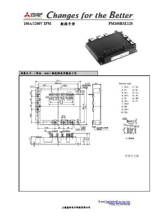
PM100RSE120数据手册
ID VD=15V,VCIN=15V,WN-VNC(下三桥总耗电流) - 60 82 mA
VD=15V,VCIN=15V,(上桥每组耗用电流)
- 15 20 mA
Von
Voff 加在输入信号端与地之间的电压
Ifo H
VD=15V,VFO=15V
1.2 1.5 1.8 V 1.7 2.0 2.3 V - - 0.01 mA
设计原理图
1. 在 PCB 布板时,光耦副边与 IPM 触发端尽可能的短。 2. 高速光耦请使用 HCPL4504。 3. 低速光耦可以使用 PC817 等。 4. 必须使用 4 组隔离电源提供控制电压。 5. 尽可能使直流母线的电感量减少,将吸收电容直接并接在 P-N 端之上。 6. 推荐使用去偶电容,以过滤噪声。
UPS 变频器 电机/司服 控制 变频电源
上海嘉尚电子科技有限公司
内部结构图
E-mail:Stephenku@ T/Fax: 021-64764189
最大额定值:
定义对象
功率器件的结温 储存温度 环境温度 过压保护值 直流浪涌 绝缘耐压 IGBT 变频侧 集电极-发射极电压 集电极电流(Tc=25) 集电极峰值电流(Tc=25) 集电极功耗(Tc=25) 制动侧 集电极-发射极电压 集电极电流 集电极峰值电流 集电极功耗 控制侧 驱动电压 输入信号电压 故障输出信号电压 故障输出信号电流
推荐工作参数 直流母线电压 驱动电压
输入“开”电压 输入“关”电压
载波频率 死区时间
Vcc
加在 P-N 之间的电压
0 < 800 V
VD
加在驱动电源侧
13.5 15.0 16.5 V
VCIN
加在信号输入端
7MBP150RA120中文资料

Mass : 920g
元器件交易网
7MBP150RA120
Characteristics (Representative)
Control Circuit
Power supply current vs. Switching frequency
Tj=100°C
80
P-side
VZ TCOH TCH TjOH TjH IOC IOC tDOC VUV VH tALM tSC RALM
Condition
Min. Typ. Max. Unit
fsw=0 to 15kHz Tc=-20 to 100°C *7
3
-
18 mA
fsw=0 to 15kHz Tc=-20 to 100°C *7
Fig.1 Measurement of case temperature
Electrical characteristics of power circuit (at Tc=Tj=25°C, Vcc=15V)
Item INV
DB
Collector current at off signal input Collector-Emitter saturation voltage Forward voltage of FWD Collector current at off signal input Collector-Emitter saturation voltage Forward voltage of Diode
Typ. -
0.05
Typ. 15 -
Max. 0.12 0.29 0.31 -
Unit °C/W °C/W °C/W °C/W
Max. 800 16.5
PM75RSE120数据手册

IfoL
VD=15V,VFO=15V
Fpwm
三相正弦
tfo
VD=15V
- 10 15 mA - 15 20 KHZ 1.0 1.8 - mS
Rth
每只 IGBT 部分
Rth
每只续流二极管部分
Rth
制动侧 IGBT
Rth
制动侧续流二极管
Rth
基板温度到结温
- - 0.3 C/W - - 0.47 C/W --- ---- 0.43 C/W ---- ---- 1 C/W - - 0.027 C/W
故障输出电流 输入载波频率 故障输出脉宽 热阻特性 瞬态热组
连接热阻
Ton
0.5 1 2.5 μs
trr VD=15V,VCIN=0-15V,Ic=20A,Tj=125℃ - 0.15 0.3 μs
tc(on)
Vcc=300V
- 0.4 1 μs
toff
- 2.5 3.5 μs
tc off
- 0.7 1.2 μs
13:UN(下桥臂驱动电源共地)
14:VN1(下桥电源正极)
15:WN(下桥 U 组信号输入)
16:FO(下桥 V 组信号输入)
产品概述:
该款智能功率模块是非常成熟第四代高频 IPM 产品。采用 1um 步线工艺,新型的快恢复二极管具有软恢复特性,内置优 化后的栅级驱动和保护电路,适合用于频率高达 20KHZ 功率变 换场合。
饱和压降测试
正向电压测试
开关时间测试
过流短路测试
上海嘉尚电子科技有限公司
E-mail:Stephenku@ T/Fax: 021-64764189
死区时间测试点
上海嘉尚电子科技有限公司
QM120C;中文规格书,Datasheet资料
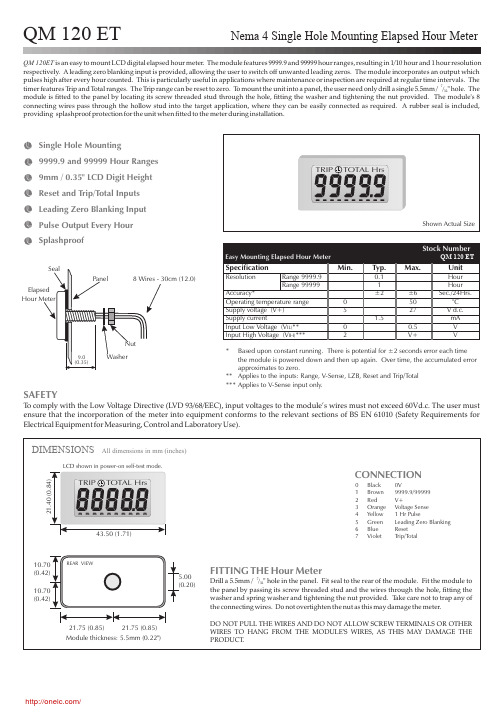
DIMENSIONSAll dimensions in mm (inches)FITTING THE Hour MeterDrill a 5.5mm /"hole in the panel.Fit seal to the rear of the module.not overtighten the nut as this may damage the meter.7/32Fit the module to the panel by passing its screw threaded stud and the wires through the hole,fitting the washer and spring washer and tightening the nut provided.T ake care not to trap any of the connecting wires.Do DO NOT PULL THE WIRES AND DO NOT ALLOW SCREW TERMINALS OR OTHER WIRES TO HANG FROM THE MODULE'S WIRES,AS THIS MAY DAMAGE THE PRODUCT .QM 120ET is an easy to mount LCD digital elapsed hour meter.The module features 9999.9and 99999hour ranges,resulting in 1/10hour and 1hour resolution respectively.A leading zero blanking input is provided,allowing the user to switch off unwanted leading zeros.The module incorporates an output which pulses high after every hour counted.This is particularly useful in applications where maintenance or inspection are required at regular time intervals.The timer features T rip and T otal ranges.The T rip range can be reset to zero.T o mount the unit into a panel,the user need only drill a single 5.5mm /hole.The module is fitted to the panel by locating its screw threaded stud through the hole,fitting the washer and tightening the nut provided.The module's 8connecting wires pass through the hollow stud into the target application,where they can be easily connected as required.A rubber seal is included,providing splashproof protection for the unit when fitted to the meter during installation."7/32Single Hole Mounting9999.9and 99999Hour Ranges 9mm /0.35"LCD Digit Height Reset and Trip/Total Inputs Leading Zero Blanking Input Pulse Output Every Hour SplashproofQM 120 ETNema 4 Single Hole Mounting Elapsed Hour MeterShown Actual SizeREAR VIEWCONNECTION0Black 0V1Brown 9999.9/999992Red V+3Orange Voltage Sense 4Yellow 1Hr Pulse5Green Leading Zero Blanking 6Blue Reset 7VioletTrip/TotalWasherElapsed Hour MeterPanel8Wires -30cm (12.0)Nut21.40(0.84)10.70(0.42) 5.00(0.20)10.70(0.42)43.50(1.71)LCD shown in power-on self-test mode.21.75(0.85)21.75(0.85)SAFETYT o comply with the Low V oltage Directive (LVD 93/68/EEC),input voltages to the module’s wires must not exceed 60Vd.c.The user must ensure that the incorporation of the meter into equipment conforms to the relevant sections of BS EN 61010(Safety Requirements for Electrical Equipment for Measuring,Control and Laboratory Use).----------Stock NumberEasy Mounting Elapsed Hour MeterQM 120 ETSpecificationMin.Typ.Max.UnitResolutionRange 9999.90.1Hour Range 999991Hour Accuracy*±2±6Sec./24Hrs.Operating temperature range 050°C Supply voltage (V+)527V d.c.Supply current1.5mA Input Low Voltage (V **00.5V Input High Voltage (V ***2V+V*Based upon constant running.There is potential for ±2seconds error each time the module is powered down and then up again.Over time,the accumulated error approximates to zero.**Applies to the inputs:Range,V-Sense,LZB,Reset and Trip/Total ***Applies to V-Sense input only.IL)IH)----------HrsTRIP TOTAL HrsTRIP TOTAL Module thickness:5.5mm (0.22")9.0(0.35)Seal/WIRE FUNCTIONS0.Black 0VNegative power supply connection.1.BrownRANGEDo not connect for 99999Hour range.Connect to 0V for 9999.9Hour range.Positive power supply connection.3.Orange V-SENSE Connect to V+to start/continue counting elapsed hours.Connect to 0V or do not connect to read TRIP or TOTAL value without counting elapsed hours.4.Yellow PULSE Normally at 0V ,this output goes High (+3.3V)every 100hour interval in TRIP mode.5.Green LZB Do not connect to display leading zeros.Connect to 0V to blank all leading zeros.When reading is 0000.0or 00000,leading zeros are not blanked.6.Blue RESETConnect momentarily to 0V to reset the display to zero (internally connected to V+via pull-up resistor).7.VioletTRIP/TOTALDo not connect for TOTAL mode operation.In TOTAL mode,the elapsed hour meter cannot be reset to zero.Connect to 0V for TRIP mode operation.In TRIP mode,the elapsed hour meter can be reset to zero.2.Red V+Specifications liable to change without prior warningQM 120 ET Issue 6September/200. Applies to QM 120 ETDISPLAY FUNCTIONS8888.8The 5digit readout displays elapsed time in hours.This symbol is displayed when trip mode is selected (see Wire Functions above)The 10-segment incrementing bar indicates that the module is working correctly and counting hours.This symbol is displayed when total mode is selected (see Wire Functions above)----------TRIP TOTAL Warning :Do not connect the following wires to V+:RANGE,PULSE,LZB,RESET,TRIP/TOTAL,as this may damage the meter.The user must incorporate suitable protection circuitry in applications where the voltage to any of the meter's wires can exceed 27V d.c.,including transient conditions,else damage to the meter may occur.In particular,for applications in harsh electrical environments,e.g.automotive,suitable external protection must be provided to protect against "load dump"conditions,transients,etc.Martel Electronics, Corp. P .O. Box 770 Londonderry, NH 03053 Toll Free: (800) 821-0023 Phone: (603) 434-1433 Fax: (603) 434-1653分销商库存信息: MARTEL-ELECTRONICS QM120C。
PMS150C datasheet V001_CN-1

PMS150C系列8位IO类型单片机数据手册第0.01版2016年3月17日Copyright 2016 by PADAUK Technology Co., Ltd., all rights reserved重要声明应广科技保留权利在任何时候变更或终止产品,建议客户在使用或下单前与应广科技或代理商联系以取得最新、最正确的产品信息。
应广科技不担保本产品适用于保障生命安全或紧急安全的应用,应广科技不为此类应用产品承担任何责任。
关键应用产品包括,但不仅限于,可能涉及的潜在风险的死亡,人身伤害,火灾或严重财产损失。
应广科技不承担任何责任来自于因客户的产品设计所造成的任何损失。
在应广科技所保障的规格范围内,客户应设计和验证他们的产品。
为了尽量减少风险,客户设计产品时,应保留适当的产品工作范围安全保障。
PMS150C不适用于交流供电阻容降压或者电源纹波大,EFT要求高的应用,请注意不要将PMS150C用于这种特殊要求的产品中。
提供本文档的中文简体版是为了便于了解,请勿忽视文中英文的部份,因为其中提供有关产品性能以及产品使用的有用信息,应广科技暨代理商对于文中可能存在的差错不承担任何责任,建议参考本档英文版。
目录1. 单片机特点 (7)1.1. 系统功能 (7)1.2. CPU特点 (7)2. 系统概述和方框图 (8)3. 引脚功能说明 (9)4. 器件电气特性 (10)4.1 直流交流电气特性 (10)4.2 工作范围 (11)4.3 IHRC频率与VDD关系曲线图 (12)4.4 ILRC频率与VDD关系曲线图 (12)4.5 IHRC频率与温度关系曲线图(校准到16MHz) (13)4.6 ILRC频率与温度关系曲线图 (13)4.7 工作电流与VDD、系统时钟CLK=IHRC/n曲线图 (14)4.8 工作电流与VDD、系统时钟CLK=ILRC/n曲线图 (14)4.9 引脚上拉电阻曲线图 (15)4.10 引脚输出驱电流(Ioh)与灌电流(Iol) 曲线图 (15)4.11 引脚输出输入高电压与低电压(V IH / V IL) 曲线图 (16)5. 功能概述 (17)5.1程序内存——OTP (17)5.2 开机流程 (17)5.3 数据存储器 – SRAM (18)5.4 振荡器和时钟 (18)5.4.1内部高频振荡器和内部低频振荡 (18)5.4.2芯片校准 (18)5.4.3 IHRC频率校准与系统时钟 (19)5.4.4系统时钟和LVR基准位 (20)5.5 16位定时器 (Timer16) (21)5.6 看门狗定时器 (22)5.7 中断 (22)5.8 省电与掉电 (24)5.8.1省电模式(stopexe) (24)5.8.2掉电模式(stopsys) (25)5.8.3 唤醒 (26)5.9 IO引脚 (27)5.10 复位和LVR (28)5.10.1复位 (28)6. IO 寄存器 (29)6.1 标志寄存器(flag),IO 地址 =0x00 (29)6.2 堆栈指针寄存器(sp),IO地址 =0x02 (29)6.3 时钟控制寄存器(clkmd),IO地址 =0x03 (29)6.4 中断允许寄存器(inten),IO地址 =0x04 (30)6.6 Timer16控制寄存器(t16m),IO地址 =0x06 (30)6.7 外部晶体振荡器控制寄存器(eoscr,只写),IO地址 =0x0a (31)6.8 中断缘选择寄存器 (integs), IO地址 =0x0c (31)6.9 端口A数字输入启用寄存器(padier), IO 地址 =0x0d (31)6.10 端口A数据寄存器(pa),IO地址 =0x10 (31)6.11 端口A控制寄存器(pac),IO地址 =0x11 (31)6.12 端口A上拉控制寄存器(paph),IO地址 =0x12 (31)6.13 杂项寄存器(misc), IO 地址 =0x3b (32)7. 指令 (33)7.1 数据传输类指令 (34)7.2 算术运算类指令 (36)7.3 移位元元运算类指令 (38)7.4 逻辑运算类指令 (39)7.5 位运算类指令 (41)7.6 条件运算类指令 (41)7.7 系统控制类指令 (42)7.8 指令执行周期综述 (44)7.9 指令影响标志的综述 (45)8. 特别注意事项 (46)8.1. 使用IC时 (46)8.1.1. IO使用与设定 (46)8.1.2. 中断 (46)8.1.3. 切换系统时钟 (47)8.1.4. 掉电模式、唤醒以及看门狗 (47)8.1.5. TIMER16溢出时间 (47) (47)8.1.6. LVR8.1.7. 指令 (47)8.1.8. RAM定义限制 (47)8.1.9. 烧录方法 (48)8.2. 使用ICE时 (48)修订历史:修订日期描述初版0.01 2016/3/17PMS150B 和PMS150C 主要差异表PMS150B 与PMS150C 主要差异列举如下:项目 功能PMS150BPMS150C1 ILRC 频率 110KHz@5.0V ,25oC 62KHz@5.0V ,25o C (VDD 变化对ILRC 有影响) 2 LVR 2.8V,2.2V,2.0V 4.0V,3.5V,3.0V,2.75V 2.5V,2.2V,2.0V,1.8V 3 RAM 60 bytes64 bytes 4 PA5口输入模式上拉电阻 没有有5 工作温度0o C ~70o C -20o C ~70o C6省电模式功耗(stopexe ) 40uA@3.3V3 uA@3.3V7 IO 输出电流 17mA/-7mA@5.0V普通模式:14.5mA/-10.5mA@5.0V低驱动模式:5mA/-3.5mA@5.0V 8 看门狗定时器溢时 4096,16384,65536 ILRC 时钟周期8192,16384,65536,262144 ILRC 时钟周期9 唤醒时间 快速模式:1024 T IHRC 普通模式:1024 T ILRC 快速模式:32 T ILRC 普通模式:2048 T ILRC 10 开机时间快速模式:2048 T IHRC 普通模式:1024 T ILRC快速模式:32 T ILRC 普通模式:2048 T ILRC 11系统保留OTP 区 0x3F8~0x3FF(8 word) 0x3F0~0x3FF(16 word)12 ILRC 做系统时钟源 ILRC,ILRC/4 ILRC,ILRC/4,ILRC/16 13支持ICE 类型PDK3S-I-001/002/003, 5S-I-S015S-I-S011. 单片机特点1.1. 系统功能◆时钟模式:内部高频振荡器、内部低频振荡器◆硬件16位定时器◆快速唤醒功能◆ 6 个带输入上拉电阻IO引脚,且做输出时具有可选的电流驱动能力◆1个外部中断输入引脚◆每个引脚都可弹性设定唤醒功能◆8级LVR可选◆工作频率0 ~ 8MHz@VDD≧3V; 0 ~ 4MHz@VDD≧2.2V; 0 ~ 2MHz@VDD≧2.0V;◆工作电压:2.0V ~ 5.5V◆工作温度:-20 o C ~70 o C◆功耗特性:I operating ~ 0.3mA@1MIPS, VDD=3.3VI operating ~ 13uA@ILRC=62KHz, VDD=3.3VI powerdown ~ 0.5uA@VDD=3.3V1.2. CPU特点◆工作模式:单一处理单元的工作模式◆ 1KW OTP程序内存◆ 64字节数据存储器◆提供79条指令◆绝大部分指令都是单周期(1T)指令◆可程序设定的堆栈深度◆所有的数据存储器都可当数据指针(index pointer)◆独立的IO地址以及存储地址方便程序开发2. 系统概述和方框图PMS150C是一个IO类型、完全静态,以OTP为程序存储基础的单片机。
UE开关资料120series中文

120-B -03性能特点.Class I, Div.1 & 2, Groups B, C & D Class II, Div. 1 & 2,Groups E,F & G Class III.有一个或二个单刀双掷(SPDT)开关,可选双刀双掷(DPDT)开关 .双端电器接口输出,方便连线.焊接膜片或波纹管.端子连线方式.开关盖有锁定功能.有微压及微差压开关压力,真空,差压开关和温度开关U N I T E D E L E C T R I CC O N T R O L S120 Series120 Series120 Series2 w w w .u e o n l i n e .c o m 120-B -03在选择工业用压力或温度开关时,经常要考虑其安全性能。
120系列产品满足了UL、CSA、ATEX等标准,可用于爆炸区域及含有强腐蚀气体环境中对设备和人员安全的保护。
120系列可以提供不同的压力,差压,真空和温度范围,同样可以提供不同的连接方式,各种不同的材料以及感压元件类型,正是由于这种灵活的选择方式使的120系列可广泛应用于各种场所,如化工,石化,炼油,油田,钻井平台,输油管线以及制药等各种工业过程。
从1931年开始,作为检测和开关技术的创始者和改革者,UE公司始终坚持把对设备,过程系统和人员的安全保护放在首位。
概要• 符合ANSI标准的法兰可 选用哈氏合金,蒙乃尔 和钽等材料 • 可选带指示的差压开关• 大部分的产品可即时供 货120 S e r i e sUltra-low "wcmodel with welded stainless steel diaphragm Differential pressure model with Option M210, Indicating moduleRemote bulb and armored capillary temperature model Welded stainless steel diaphragm pressure model技术参数储存温度 -65 to 160℉(-54—71℃)环境温度 -58 to 160℉(-50 to 71℃);36-39型,520-525型,540-548型,701-705型:0 to 160℉(-17 to 71℃);820E型,822E型:-40 to 160℉(-40 to 71℃) 环境温度每变化50℉(28℃),设定点典型漂移值小于全量程的1%,E121和E122型,漂移值小于2%。
日本三菱IPM智能型IGBT

QM75DY-2H
75A/1000V/2单元
450元
QM50DY-H
50A/600V/2单元
270元
QM75DY-2HB
75A/1000V/2单元
580元
QM50DY-2H
50A/100V/2单元
360元
QM100DY-HK
100A/600V/单元
390元
QM50DY-2HB
50A/1000V/2单元
30A/300V
380
元
RM500DZ/CZ/UZ-2H
60A/1600V
345
元
RM100SZ-6S
100A/300V
530
元
RM500DZ/CZ/UZ-M
100A/400V
365
元
RM200DA-24F
200A/1200V
875
元
RM500DZ/CZ/UZ-H
100A/800V
410
元
RM200HA-20F
RM400HA20S
400A/1000V
1000
元
RM500DZ/CZ/UZ-M
150A/400V
500
元
RM400HA-24S
400A/1200V
1100
元
RM500DZ/CZ/UZ-H
150A/800V
520
元
RM500HA-M
500A/400V
1125
元
RM500DZ/CZ/UZ-24
150A/1200V
30A/1200V/6单元
680元
QM15KD-HB
15A/600V/6单元
220元
- 1、下载文档前请自行甄别文档内容的完整性,平台不提供额外的编辑、内容补充、找答案等附加服务。
- 2、"仅部分预览"的文档,不可在线预览部分如存在完整性等问题,可反馈申请退款(可完整预览的文档不适用该条件!)。
- 3、如文档侵犯您的权益,请联系客服反馈,我们会尽快为您处理(人工客服工作时间:9:00-18:30)。
INSULATED PACKAGE
INSULATED PACKAGE
INSULATED PACKAGE
3.53.5—
———
Main terminal screw : M5Mounting part
screw : M5
—Symbol Parameter
Mounting torque Mounting torque Weight
Test Condition
Unit N • m N • m g
Limits Min.Typ.Max.2.52.5—
3.03.0920
MECHANICAL RATINGS AND CHARACTERISTICS
V D = 15V , V CIN = 15V Applied between :U P -V UPC , V P -V VPC , W P -V WPC
U N • V N • W N -V NC I D °C V mA ms
62201.82.3————125—12.5—0.0115—
mA Circuit Current
Input ON Threshold Voltage Input OFF Threshold Voltage Over Current
Trip Level
Short Circuit Trip Level Over Current Delay Time Over Temperature Protection Supply Circuit Under-Voltage Protection
Fault Output Current Minimum Fault Output Pulse Width
V th(on)V th(off)OC SC t off(OC)OT OT r UV UV r I FO(H)I FO(L)t FO
CONTROL PART
——1.21.7282200——111—11.5———1.0
Parameter
Symbol Test Condition
Max.Min.Typ.Unit Limits 45151.52.0410—5401011810012.012.5—101.8
(Note-3)Fault output is given only when the internal OC, SC, OT & UV protection.
Fault output of OT protection operate by lower arm.Fault output of OC, SC protection given pulse.
Fault output of OT, UV protection given pulse while over level.
Base-plate
Temperature detection, V D = 15V –20 ≤ T j ≤ 125°C V D = 15V , V FO = 15V (Note-3)V D = 15V
(Note-3)
V µs V D = 15V
(Fig. 5,6)
–20≤ T j ≤ 125°C, V D = 15V (Fig. 5,6)V D = 15V (Fig. 5,6)V N1-V NC V XP1-V XPC
T j = 25°C T j = 125°C
A A Trip level Reset level Trip level Reset level
RECOMMENDED CONDITIONS FOR USE
Recommended value
Unit Test Condition
Symbol Parameter
V Applied across P-N terminals
Applied between :V UP1-V UPC , V VP1-V VPC
V WP1-V WPC , V N1-V NC (Note-4)
Applied between :U P -V UPC , V P -V VPC , W P -V WPC
U N • V N • W N -V NC
Using Application Circuit input signal of IPM, 3φsinusoidal PWM VVVF inverter (Fig. 8)For IPM ’s each input signals
(Fig. 7)
Supply Voltage Control Supply Voltage Input ON Voltage Input OFF Voltage PWM Input Frequency Arm Shoot-through Blocking Time
≤ 800
15±1.5≤ 0.8≥ 4.0≤ 20≥ 3.0
V CC V CIN(on)V CIN(off)f PWM t dead
V D V kHz µs
V (Note-4)Allowable Ripple rating of Control Voltage : d v /d t ≤ ±5V/µs, 2V p-p
INSULATED PACKAGE
INSULATED PACKAGE。