PM500电力参数测量仪安装和用户手册
PM1000电力参数测量仪安装和用户手册-201001版
PowerLogic PM1000系列电力参数测量仪安装和用户手册DM1000 电力监控测量仪安装使用指南一:安全说明危险类别和专用符号在准备安装、操作、服务或维护前,要认真阅读说明书,熟悉设备。
下面的特定信息可能贯穿于整个说明书或贴在设备上,提醒您注意潜在的危险,或者让您注意那些阐述或简化过程的信息。
安全标志“Danger “(危险)或“Warning ”(警告),存在其中任一图标,表示存在电气危险,如果不按说明操作,会导致人身伤害。
是安全警示标志。
用于提醒您可能的人身安全危险。
应遵循此标志后所示的安全信息,以避免引起的伤害或死亡。
二:快速安装请按如下图所示接线1. 将控制电源44~277VAC/DC 连接到端子12和13上;以下的快速安装p 保持2秒,使设备通电p EDIT A PRI 100.0以下是进入编辑页面的简单操作p 进入参数设置页面,调试精确数值pA.pri, A.sec 分别代表CT 互感器原边、副边的数值。
例如:如果CT 变比为200:5, 原边A.pri = 200.0 那么副边A.sec = 5.000.p 如果输入电压小于480 VAC (线电压),可在PROG 页面设置V.pri, V.sec 的数值。
例如:输入电压为300 VAC (线电压),那么原边的电压 V.pri = 300.0V 及副边的电压 V. sec = 300.0V输入电压在480VAC 以上,需要加装电压互感器(PT/VT)分别设置电压互感器原边、副边的数值。
例如,互感器的变比是11 kV:110 V, 原边的值V.pri =11.00 k 及副边的值 V.sec = 110.0系统接线类型p SYS - STAR/WYE 代表三相四线系统p SYS – DLTA 代表三相三线系统p SYS - 2 Phase 代表两相三线系统p SYS - 1 Phase 代表单相两线系统2. 使用电流互感器 CT1 CT2 CT3 端子 1,2 3,4 5,63. 使用电压互感器 PT1(VT1) PT2(VT2) PT3(VT3) ( 在输入线电压超过480 VAC 的情况下使用)端子 8 9 10 (11是连接中性线的端子)4. RS 485 通讯接口 7(+ve), 14(-ve) (只有DM6200有此通讯接口)注意:电气设备的安装、连接、调试都应在专业人员的指导下完成,对于因不遵守本手册的说明所引起的故障,施耐德电气不承担任何责任。
PM500 电压调节器安装,操作和维护手册说明书

Maintenance ManualA Regal BrandIntroductionThe PM500 is an encapsulated electronic voltage regulator intended for use with the Marathon PMG systemand most Marathon AC generators. The PM500 controls the output of a brushless AC generator by regulating the DC current input to the exciter field. The PM500 is designed as a three phase or single phasetrue RMS sensing regulator that is capable of accepting analog voltage adjustment input. The PM500 is UL Recognized and UL Certified for Canada – Component per UL File E222903. The PM500 bears the CE markfor the European Union.SpecificationsSensing Input175 - 600Vac, True RMS, 60/50Hz, 3 Phase/1 PhasePower Input 175 - 260Vac, 300Hz PMG, 60/50Hz ShuntPower Output, Continuous 85Vdc at 3.5Adc with 240Vac input powerPower Output, Forcing 170Vdc at 7Adc for 10 sec. with 240Vac input powerFuse 5 x 20mm S505-5A, Slow Blow TypeVoltage Regulation ± 0.25%, with 4% engine governingExcitation Resistance9 ohms, minimumOver Excitation Protection Excitation exceeds 190Vdc or 7Adc for more than 10 seconds Manual Voltage Adjustment Range ± 20% with 2000 ohm rheostat± 10% with 1000 ohm rheostatAnalog Voltage Input A1 & A2 ± 20% with 0-10Vdc or ± 5Vdc biasUnder Frequency Factory Setting 58Hz preset for 60Hz operation and 48Hz preset for 50Hz operation Voltage Build-up Voltage build up from input voltage ≥ 5Vac at 25Hz.Response Time<1 CycleWeight16.6 oz.Operating Temperature -40°C to +60°CStorage T emperature -40°C to +85°CPower Dissipation12 watts, maximumSize 5.9” L x 5.3” W x 2.2” HThermal Drift 0.05% / °C change in AVR ambient temperature Electromagnetic Compatibility TestsImmunityIEC61000-4-2 - Electrostatic DischargeIEC61000-4-3 - Radiated RFIEC61000-4-4 - Electrical Fast TransientIEC61000-4-5 - SurgeIEC61000-4-6 - Conducted RFIEC61000-4-11EmissionEN61204-3 - Conducted RFCISPR 22IEC61000-3-2 - Harmonic IECIEC61000-3-3 - Flicker IEC2InstallationMOUNTINGThe PM500 is mounted through a keyed hole in the generator conduit box and secured with a plastic mounting nut.The PM500 should be mounted directly to the conduit box panel with the rubber gasket positioned between the outside of the conduit box panel and the mounting nut.Protect front panel adjustment pots by installing clear or black plastic cover.Mounting nut torque is 26 – 43 lbf-in. Refer to the Figure 1 for dimensions.Wiring and ConnectionsEXCITER FIELD POWER CIRCUITThe exciter field resistance must be ≥ 9 ohms.If the exciter field resistance is less than 9 ohms andthe full load field current does not exceed 3.5 amps, add a resistor in series of sufficient wattage to increase the total resistance to 9 ohms.Connect the generator F+ (F1) field lead to the regu- lator F+ terminal. Connect the generator F- (F2) field lead to the regulator F- terminal. Refer to Figure 3 for typical connection points.POWER I NPUT C IRCUITThe PM500 is designed to be powered by a PMG and capacitor. A 7.5µƒ capacitor is connected in parallel between the PMG leads and the regulator power input terminals.The regulator power input terminals are labeled P1 and P2. Connect leads from P1 and P2 to the capacitor terminals.Connect regulator terminals P1 & P2 to generator leads that will provide 240Vac output. No capacitor is used with the PM500 in shunt mode.Refer to Figure 3 for typical connection points.Figure 23TO PREVENT PERSONAL INJURY OR EQUIPMENT DAMAGE, ONLY QUALIFIED PERSONNEL SHOULD INSTALL, OPERATE OR SERVICE THIS DEVICE.Figure 1Wiring and Connections (cont’d)Figure 3a – Three PhaseFigure 3b – Single PhaseSENSING CIRCUITSSensing input range is 175 - 600Vac. DIP switch SW1 and SW2 must be set appropriately. Refer to Figures 3a & 3b for typical connections.Single Phase SensingConnect PM500 terminal E1 to output lead L1 and E2 to output lead L2. PM500 terminal E3 is jumpered to E2. 3 Phase SensingConnect PM500 terminal E1 to output lead L1, E2 to output lead L2 and E3 to output lead L3.If used in a paralleling application, a paralleling CT will be required in the generator B phase. Paralleling CT must be sized to provide either a 1A or 5A signal when the generator is under full load.4Wiring and Connections (cont’d)DIP SWITCH PROGRAMMINGEight DIP switches located on the back of the regulator must be set appropriately for correct regulator operation and generator control. Refer to Figure 4.Switches 1 & 2 set the regulator sensing range.Switches 3 – 8 Configure multiple functions: 3 or Single Phase Sensing, Frequency, Over Excitation Protection, kW Range and Paralleling CT Range.SW1 : OFF SW2 : OFF Volts ≤ 280VacSW1 : OFF SW2 : ON Volts ≤ 480VacSW1 : ON SW2 : ON Volts ≤ 600VacOFF ONSW3 : 3 Phase Sensing 1 Phase SensingSW4 :60 Hz 50 HzSW5 :O/E Protect On O/E Protect OffSW8 :CT 1A CT 5ASW6 : OFF SW7 : OFF< 90kWSW6 : ON SW7 : OFF90 - 500kWSW6 : ON SW7 : ON> 500kW PROTECTION F UNCTIONSThe PM500 has built in protection functions for Over Excitation, Under Frequency and Over Voltage Protection.Over ExcitationThe Over Excitation function protects the PM500 and generator components in the event the excitation system demands excessive levels of voltage and/or current to maintain output.The Over Excitation function will trip when excitation output exceeds 190Vdc or 7Adc for more than 10 sec. with 220Vac input power.The Over Excitation O/E LED on the front panel will be illuminated when thePM500 when the OverExcitation system has tripped. Replace the fuse on theback panel if required and inspect the generator. ThePM500 will reset when power is cycledUnder FrequencyUnder Frequency protection allows the generatorvoltage to decrease when the output frequency dropsbelow the Roll-Off point. This reduces the load on theengine, allowing engine RPM to recover. This is normaloperation and no reset is required.5 Figure 4Operating AdjustmentsSix adjustable potentiometers are accessible on the front panel of the PM500. These are: VOLT, STAB, U/F, DIP, DROOP and TRIM.Figure 6VOLTAGE ADJUST (VOLT)Set PointOutput voltage may be adjusted via the VOLT poten- tiometer on the front panel of the regulator. The set point range is 175 - 600Vac.Remote Voltage AdjustA 2000 ohm, 2 watt rheostat may be connected to VR1 and VR2 - replacing the factory jumper, providing a ±10% voltage adjustment range. T erminals A1 & A2 may not be used when a rheostat is installed.Analog Voltage AdjustRegulator terminals A1 & A2 may be connected to the analog output of a gen-set controller. The allowable voltage input range is 0-10Vdc or ± 5Vdc will provide a 20% range. Jumper VR1 & VR2 when analog voltage adjustment terminals are used.TRIM ADJUST (TRIM)The analog bias range is adjusted via the TRIM potenti-ometer on the front panel. Set the TRIM potentiometer fully clockwise to provide a ± 20% adjustment range. DROOP ADJUST (DROOP)Requires a 1A or 5A CT in the B Phase.DIP switch SW8 must be set appropriately.In a paralleling system, the PM500 adjusts the genera- tor output voltage when the B phase current leads or lags the B phase voltage.The adjustment range may be preset via the DROOP potentiometer. The default setting is full counter clock-wise for minimum range. Maximum range is ±7% at 1.7 PF lagging to 0.7 PF leading.UNDER FREQUENCY ROLL-OFF ADJUST (U/F) The Roll-Off point is the frequency at which the gen- erator output voltage is allowed to decrease and is factory preset at 57Hz for 60Hz operation and at 47Hz for 50Hz operation.When the U/F LED on the front panel it lit, the PM500 is operating in Under Frequency mode.To change the roll-off point, first verify that the gen-set is operating at the intended speed and voltage.Fixed Engine RPMOn most new engines (Tier 4i and up), the engine speed is fixed at 1800RPM or 1500RPM.Adjust the roll-off point by block loading the genera-tor and observing the U/F LED on the front panel. To ensure the generator maintains voltage under a given block load, adjust U/F potentiometer until the U/F LED remains off during the block load test.Adjustable Engine RPMAdjust engine speed to the new roll-off point. Verify that the output voltage still matches the intended set-point voltage.Next, adjust the U/F potentiometer clockwise until the voltage starts to drop off, then slightly adjust the poten- tiometer counterclockwise until the voltage returns to rated voltage. Re-adjust engine speed to rated speed. U/F DIP ADJUST (DIP)When Under Frequency (U/F) protection is activated, the voltage dip follows a linear Volts / Hertz curve. The voltage dip ratio may be adjusted via the DIP potentiometer with an adjustable range of 3-10V/Hz. The default setting is full clockwise for 10V/Hz. STABILITY ADJUST (STAB)Stability is the ability of the generator to respond to load changes. Decreasing the stability setting allows the generator to respond faster to load changes. If the stability setting is too low, the generator voltage will tend to hunt under steady state conditions.Correct stability adjustment must be conducted while the generator is operating unloaded.Adjust the STAB potentiometer clockwise until the voltage becomes unstable, then slightly adjust coun- terclockwise (Approximately 1/5 turn) until the voltage becomes stable.6Warnings & CautionsIMPORTANT INFORMATIONPlease Read CarefullyThis document is not intended to provide operational instructions. Appropriate Marathon Electric instructions provided with the generator and precautions attached to the generator should be read carefully prior to installation, operations and/or maintenance of the equipment. Injury to personnel or generator failure may be caused by improper installation, maintenance or operation.The following and information is supplied to you for your protection and to provide you with many•Buyer shall be solely responsible for determining the adequacy of the product for any and all uses to which Buyer shall apply the product. The application by Buyer shall not be subject to any implied warranty of fitness for a particular purpose.•For safety, Buyer or User should provide protective guards over all shaft extensions and any moving apparatus mounted thereon. The User is responsible for checking all applicable safety codes in his area and providingsuitable guards. Failure to do so may result in bodily injury and/or damage to equipment.•Hot oil can cause severe burns. Use extreme care when removing lubrication plugs.•Disconnect power and lock out drive equipment before working on a generator.•Always keep hands and clothing away from moving parts.•The lifting eyes on the generator are not to be used to lift the entire generator set. Only the generator may be safely lifted by the lifting eyes. Do not use the conduit box for lifting or support of the generator.•Install and ground the generator per local and national codes.•Discharge all capacitors before servicing the generator.•Misapplication of a generator in a hazardous environment can cause fire or an explosion and result in serious injury.•Never attempt to measure the temperature rise of a generator by touch. Temperature rise must be measured by thermometer, resistance, imbedded detector or thermocouple.•Operation of a generator at higher than its nameplate ratings may result in fire, damage to equipment or serious injury to personnel.•Do not apply any force to the generator fan when rotating the generator rotor.•Generators should not be operated faster than their rated speed.•The following statement is only applicable to high voltage generators (above 5000 V). A grounding strap is supplied from the generator neutral to ground. This grounding strap not only bleeds off any voltage potential on the main statorafter the high potential test, but also bleeds off any static charge that can build-up on the main stator during shipmentand storage. THIS GROUND STRAP IS NOT A PERMANENT PART OF THE GENERATOR CONSTRUCTION. REMOVETHIS GROUND STRAP ONLY AFTER A PERMANENT GROUND IS INSTALLED ON THE GENERATOR MAIN STATOR(not supplied by Marathon Electric), OR THE GENERATOR FINAL INSTALLATION IS COMPLETE.•Mounting bolts should be routinely checked to ensure that the unit is firmly anchored for proper operation.•Consult qualified personnel with questions. All electrical repairs must be performed by trained and qualified personnel only.•For inverter applications, follow the inverter manufacturer’s installation guidelines.•Make sure the generator is properly secured and aligned before operation.•When installing the generator, insure that loose parts or tools do not fall inside the generator.•When connecting the generator, be sure to follow the correct wiring diagram for the desired voltage. Insure that the voltage regulator is connected per the wiring diagram.RESALE OF GOODSIn the event of the resale of any of the goods, in whatever form, Resellers/Buyers will include the following language in a conspicuous place and in a conspicuous manner in a written agreement covering such sale:The manufacturer makes no warranty or representations, express or implied, by operation of law or otherwise, as to the merchantability or fitness for a particular purpose of the goods sold hereunder. Buyer acknowledges that it alone has deter- mined that the goods purchased hereunder will suitably meet the requirements of their intended use. In no event will the manufacturer be liable for consequential, incidental or other damages. Even if the repair or replacement remedy shall be deemed to have failed of its essential purpose under Section 2-719 of the Uniform Commercial Code, the manufacturer shall have no liability to Buyer for consequential damages.Resellers/Buyers agree to also include this entire document including the cautions and warnings above in a conspicuous place and in a conspicuous manner in writing to instruct users on the safe usage of the product.This information should be read together with all other printed information supplied by Marathon Electric.For more information contact: Regal Beloit America, Inc., 100 E. Randolph St., Wausau, WI 54401Phone: 715-675-3311 or Fax: 715-675-80267A Regal Brand100 E. Randolph Street PO Box 8003Wausau, WI 54402-8003 U.S.A. PH: 715-675-3359 FAX: 715-675-8026 ©2019 Regal Beloit Corp GPN056 v1.2100/11-19/FSPrinted in the U.S.A.。
电参数测量仪操作规程
电参数测量仪操作规程
《电参数测量仪操作规程》
一、前言
电参数测量仪是一种用来测量电路中各种电参数的仪器,包括电压、电流、功率等。
为了保证仪器的正常使用和操作的安全性,制定了以下的操作规程。
二、仪器准备
1. 检查电参数测量仪的外观是否有损坏,如果发现任何损坏,不得进行使用。
2. 确保测量仪的电源连接正确,插头应该插牢固,不得出现松动。
3. 启动测量仪前应对仪器进行必要的预热和校准。
三、正常操作
1. 开机
2. 选择测量模式
3. 设置参数
4. 连接电路
5. 进行测量
6. 记录数据
7. 关机
四、特殊情况处理
1. 在操作过程中,如果发现电参数测量仪出现异常现象,应立即停止使用并进行检查处理。
2. 如果在操作过程中出现电路异常,如漏电、过载等,应按照安全操作规程处理。
五、操作注意事项
1. 在进行测量前,应检查被测电路是否已断电,避免发生触电事故。
2. 在操作过程中,应注意仪器和电路的连接是否牢固,避免接触不良和短路。
3. 操作人员应穿戴静电防护设备,以防止静电对测量结果的影响。
六、注意事项
1. 测量仪器的保养和维护是保证仪器正常运行的重要保障,必须经常对仪器进行清洁和检查。
2. 在使用过程中,若发现测量仪器有异常或损坏,请立即停止使用,并通知维修人员进行处理。
七、结语
遵守以上规程并严格按照操作步骤进行操作,可保证电参数测量仪的正常使用和人身安全。
任何违反规程导致的损坏或事故,相关责任人将承担相应的责任。
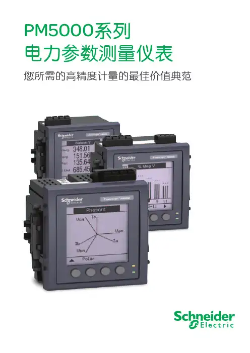
PM5000电力参数测量仪表
谐波
- 支 持 THD 总 谐 波 失 真 测 量 和 单 次 谐 波 测 量,PM5100 可达 15 次,PM5300 达 31 次, PM5500 可达 63 次
双以太网口(PM5500 系列)
- 将仪表以菊花链的形式连接,减少接线和对 交换机或路由器的需求。每个仪表有一个单 独的 IP 地址
- 紧凑的 72 毫米厚度,节省柜内空间
图形显示
- 明亮的显示屏具有极佳的抗反光性,即使在 强光和大视角环境下也可以获得良好的视觉 效果
- 直观的菜单导航,多种图形及图表显示,并 提供汉语、英语、西班牙语、法语、意大利语、 德语、葡萄牙语和俄语选择,方便获取重要 信息
内置 Web 网页(PM5500 系列)
优化能源成本管理
一个兼具多种特性于一体的完美组合,融合了行业领先的测量精确度,以满足建筑及工业中 诸如多费率计量和数据记录等能源成本管理应用的要求。它符合 IEC 62052/53、61557-12 仪 表标准,PM5000 系列电力参数测量仪表不仅解决了以往能源成本账单的不确定性,同时确 保了那些不规范设备无法企及的高性能水平。
- 可编程报警可以触发数字输出和继电器输出 (PM5300 系列 )
数字输入 / 输出
- 监视报警情况,使需量与外部脉冲、计数脉 冲同步,并从其他能源仪表获取信息以计算 全能源消耗
- 使用数字输出向其他设备或者软件发出信 号,或者执行自动化操作例如对基本设备的 控制或报警
四线电流输入(PM5500 系列)
目前,施耐德电气在中国共建立53个办事处,28家工厂,7个物流中心,1 个研修学院,3个全球研 发中心,1000多名研发工程师,1 个实验室,1 所能源大学,700多家分销商和遍布全国的销售网 络。施耐德电气中国目前员工数近28,000人。通过与合作伙伴以及大量经销商的合作,施耐德电气
PM测试软件使用手册

本手册适用于软件版本 V1.03 Copyright © 2009-7-24本手册版本V1.01北京博电新力电力系统仪器有限公司版权所有本手册中的产品信息、说明以及所有技术数据均不具有合同约束力。
北京博电新力电力系统仪器有限公司(下简称北京博电公司)保留对产品技术数据进行修改而不另行通知的权利。
产品与本手册不符之处,以实际产品为准。
北京博电公司对于本手册中可能发生的错误不承担责任。
未经北京博电公司书面许可,不得全部或部分拷贝、重印该手册。
注意事项PM测试软件是与PM系列电力自动化测试装置配套使用的专用测试软件。
PM测试软件安装在台式或便携式计算机上,运行在Windows XP操作系统下。
PM测试装置使用USB信号线或以太网双绞信号线与计算机连接,由PM测试软件对测试装置进行联机控制。
联机工作时应保证信号线可靠连接,注意不要随意拉扯信号线或晃动信号线连接端。
PM测试装置为高精度电子仪器;为保证输出和测量的精度,装置开机后应预热30min以上。
目录注意事项 (3)目 录 (4)1.软件概述 (6)1.1. 软件启动 (6)1.2. 测控装置功能测试 (7)1.3. 计算机监控系统功能测试 (8)1.4. 变送器功能测试 (8)2.软件和通讯驱动程序安装 (9)2.1. 软件安装 (9)2.2. USB口装置驱动程序安装 (9)3.通讯设置 (15)3.1. PM设备接口选择 (15)3.2. 网口PM设备联机通讯设置 (16)3.3. 闭环通讯设置 (20)4.手动测试 (25)4.1. 概述 (25)4.2. 测试参数设置 (26)4.3. 手动输出 (30)5.交流采样自动测试 (31)5.1. 概述 (31)5.2. 测试参数设置 (33)5.3. 测试接线 (42)5.4. 测试操作 (43)6.变送器自动测试 (47)6.1. 概述 (47)6.2. 测试参数设置 (48)6.3. 测试接线 (56)6.4. 测试操作 (56)7.同期测试 (58)7.1. 概述 (58)7.2. 测试参数设置 (60)7.3. 测试接线 (65)7.4. 测试操作 (66)8.谐波测试 (68)8.1. 概述 (68)8.2. 测试参数设置 (68)8.3. 谐波输出 (69)8.4. 谐波测试实例 (69)9.系统测试 (70)9.1. 概述 (70)9.2. 测试参数设置 (71)9.3. 测试接线 (75)9.4. 测试操作 (75)附录A 点表设置程序使用说明 (77)附录B 点表命名说明 (89)附录C 交流采样闭环校验报告实例 (91)1.软件概述PM测试软件是与PM系列电力自动化测试装置配套使用的专用测试软件。
数字式电参数综合测试仪器操作规程
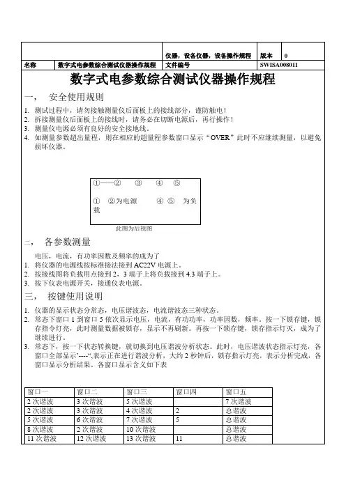
1.注意防水,防尘,防摔。
2.不宜在高温高湿,易燃易爆和强磁场的环境下存放,使用仪器。
3.使用湿布和温和的清洁剂清洁仪器外表,不要使用研磨剂及溶剂。
4.在仪器使用完毕之后,要注意切断电源,防止过长时间的使用而减少仪器的使用寿命。
制定
批准
页码
2/2
3.按下仪表电源开关,接通仪表电源。
三,按键使用说明
1.仪器的显示状态分常态,电压谐波态,电流谐波态三种状态。
2.常态下窗口1到窗口5依次显示电压,电流,有功功率,功率因数,频率。按一下锁存键,锁存指令灯亮,此时测量数据被锁存,显示不再刷新。再按一下锁存键,锁存指示灯灭,成为了继续进行。
3.常态下,按一下状态转换键,就切换到电压谐波分析状态。此时,电压谐波状态指示灯亮,各窗口全部显示’----“,表示正在进行谐波分析,大约2秒钟后,锁存指示灯亮,表示分析完成,各窗口显示分析结果。各窗口显示含义如下表
4.在电压谐波分析状态下,按一下状态转换键,就切换到电流谐波分析状态。此状态下各窗口显示含义及按键操作均等同于电压谐波态。在此状态下按一下专题转换键,就切换到常态。
5.
6.无论在哪一种状态下,按打印键偶可以把测量的结果打印出来,打印内容包括:电压,电流,功率因数,电压谐波分量,电流谐波分量,电压波形,电流波形。
仪器,设备仪器,设备操作规程
版本
0
名称
数字式电参数综合测试仪器操作规程
文件编号
SWISA008011
数字式电参数综合测试仪器操作规程
一,安全使用规则
1.测试过程中,请勿接触测量仪后面板上的接线部分,谨防触电!
2.拆接测量仪后面板上的接线时,请务必在切断电源后,再行操作!
电参数仪操作规程
文件编号:
版本/次:A/0 总页数:1 文件名称:电参数仪操作规程生效日期
一、人员要求:
操作人员应为经过培训的实验室人员、工程部人员、品质部人员和产线员工。
二、仪器介绍:
电参数测量仪可测量电压、电流、功率、功率因数等参数
三、开机前检查:
1.检查仪器是否正常供电,检查仪器外壳是否完好无损。
2.检查仪器各端口的接线,检查仪器的输入电源是否有接地线。
四、开机后检查:
1.检查仪器是否正常开启,是否有报警,如有报警按注意事项执行。
五、仪器设定及条件:
1.电源电压:220V/50HZ
2.按实际需要设定报警值
六、注意事项:
1.做好设备日常维护保养。
2.如出现其它报警或者故障,必须先切断电源,非专业人员严禁自行处理。
3.切断电源后应等待 5 秒之后才能再次打开电源,否则仪器可能显示不正常。
4.操作结束或下班必须关闭电源。
5.点检要求:每周一次。
七、操作步骤:
1.按要求执行开机检查。
2.检查无误后启动仪器。
3.按要求执行开机后检查。
4.检查参数设定,按需求设定报警值。
5.将需要供电的物品与仪器输出端连接。
6.长期不使用关闭仪器。
编制:审核:批准:
1。
电参数综合测试仪设备操作规程
电参数综合测试仪设备操作规程第一章总则第一条为了保证电参数综合测试仪设备的正常运行,保护设备和人员的安全,制定本操作规程。
第二条本操作规程适用于电参数综合测试仪设备的操作人员。
第三条所有操作人员应严格遵守本操作规程,严格执行操作要求,确保操作过程顺利进行。
第二章设备基本知识第四条电参数综合测试仪是一种用于测试电力系统、电力设备及相关电器设备电气参数的设备。
第五条电参数综合测试仪设备由主机、外接电缆、测量传感器、测试软件等组成。
第六条电参数综合测试仪设备主机应放置在通风良好、干燥、无腐蚀气体的室内。
第七条电参数综合测试仪设备应有专门的仪器柜或操作台,整洁有序。
第三章设备操作要求第八条操作人员在使用电参数综合测试仪设备前,应仔细阅读设备的操作手册和技术资料,熟悉设备的使用方法和相关注意事项。
第九条操作人员应正确接线,避免短路或错接导致设备损坏或事故发生。
第十条操作人员应严格按照操作步骤进行设备操作,不得擅自更改设备的参数或运行模式。
第十一条操作人员在操作设备过程中要保持清醒状态,严禁饮酒、吸烟等影响工作的行为。
第四章设备日常维护第十二条操作人员应定期对设备进行检查,确保设备的正常运行。
第十三条在使用过程中发现任何异常情况,应及时停止使用设备,并向上级报告。
第十四条操作人员应定期对设备进行保养,包括清洁设备外壳、检查仪器仪表的工作状态等。
第十五条设备长时间不使用时,应切断电源,并将设备包好防尘存放。
第五章安全注意事项第十六条操作人员在操作设备时,应穿戴好防护用具,避免触电、烫伤等事故发生。
第十七条操作人员应严格遵守电气安全操作规程,确保用电安全。
第十八条操作人员在操作设备时应注意长时间高柱、高压等工况对身体的影响,适时休息。
第十九条操作人员在操作设备时,应保持设备周围的通道畅通,避免杂物堆放引发事故。
第六章违章处理第二十条对于违反本操作规程的操作人员,根据违纪程度轻重,将视情况给予批评教育、通报批评、暂停操作资格等处理,并可以追究相应的法律责任。
PM500
件号:50983 与外部同步 或者输入数字
100ms 到 900ms , 步 长 为 100ms
本地 ■ ■ ■ ■
■
操作 远程
■
■ ■
■பைடு நூலகம்
IO22 告警选项
件号:50984
功能
带脉冲计数的两个数字输入
两个继电器输出
通过 Modbus 的控制
或者高/低阈值告警
输出设定
两个输出独立设定
控制方式
或者告警方式
0 到 99 999 999 kVah
运行时间
(百分制时间)
需求值
电流
相和中线
有功,无功,视在功率 总值
最大需求值
最大电流
相和中线
最大有功功率(四个象限) 总值
最大无功功率(四个象限) 总值
最大视在功率
总值
电气质量值
总谐波失真(THD)
电流和电压
复位
最大需求电流和功率
能量值和运行次数
输入计数器(2)
注:2-CT 解决方法将使相精度 降低 0.5%。(电流的降低是由于 矢量运算所造成的)。
建议: 输入电压保护设备的选定必须与接线端的短路电流相匹配。
安装和用户手册
IO11 Puls 选项
选装模块的连接
IO22 告警选项
RS485 Modbus 选项
建议: 为了避免损坏模块,在进行任何连接前应先检查参数限制(参 见原文 114 页)。
AO20 4-20 mA 选项
用 2-线方式与其他主电路 或从电路连接
(*)如箭头所示,翻转开关 1 和 2,可以插入 120Ω线性终端电阻。 注:有关Modbus通信接口的更多信息,请参见Schneider 电力 Modbus网络指南。
电参数综合测试仪设备操作规程
二、设备型号:2102B
三、生产单位:艾诺仪器公司
四、工作环境:
环境温度:25℃±10℃
相对湿度:≤75%RH
五、技术指标:
测试电压:AC 20.0V~300.0V(45~400HZ)
测试电流:2A~20A
有功功率:0.4W~12.00KW
功率因数:0.100~1.000
5、接通负载电源,测量仪将显示测量电压值、电流、功率、功率因数以及负载电源频率等参数。
6、记录测试数据。
7、试验结束后,先将负载电源关断,然后再拆除仪表后面的接线。
七、注意事项:
1、开始测量时请勿接触测量仪后面的接线端子,以防触电。
2、试验前应通过“参数”以及数值设定键先将电压变比与电流变比设定为默认值1。
六、操作方法:
1、将仪表电源线的一端插入测量仪的电源插孔,另一端插入220V/50HZ电源插座。
2、按下测量仪前面板上的仪表电源按钮,打开仪表电源,电源指示灯亮。
3、先上。
4、先将负载电源的输出开关断开,然后将负载电源接到仪表的负载电源的连接端子上。
- 1、下载文档前请自行甄别文档内容的完整性,平台不提供额外的编辑、内容补充、找答案等附加服务。
- 2、"仅部分预览"的文档,不可在线预览部分如存在完整性等问题,可反馈申请退款(可完整预览的文档不适用该条件!)。
- 3、如文档侵犯您的权益,请联系客服反馈,我们会尽快为您处理(人工客服工作时间:9:00-18:30)。
Modbus !" ! !"#
!"
!
"#$
Modbus RS485
!50982
RS485 JBUS/Modbus ! ! !
2 ! 1 255 2400 38400 ! "! 1 2
!"#$
3
2
!"#$
PM500 !"#$ !"#$%&'()# PM500 !"#$%& !"#$%&'()* !"#$%&'( !"#$%&'()*
! (AUX) !"#$"% : !"#50980 110 400 V AC 10 % 120 305 V DC 20 % !"#50981 24 48VDC 10 % DC !"#$%&'( !"#$%&'()*+,-./&0123401 !" AC / DC
!"#$
5
4
PM500
480V
!"#$%& : 4 3CT
!"#$
(
!" #$% !"#$% 15 )
!"#$IO11Puls
!"#$EXT
!"#$%&'()*+,-
!"#$
23
6
!"#$%&
!"15 !"#$ !"# !"# !"#$%&'()*
!"#
!"#
!
15 ( 10 8 5 EXT ( 60 30 20 )
ou
!)
!"#$
(
!" #$ !"#$%& 15 )
!"#$%&'()
1 2 (Back lit) !"#$ !"#$%&'()*+,-./0
E78241
!"#$%&'()
1 2 3 !"#$%& !"#$% !"#$ %&' ()*+,
E78240
!
!
!"#$PM500 !" !"#$%&
!
!"#$%&' : 1 2 3 4 !"PM500 !" # !"#/ !"#$%& : 1 2 3 4 5 !"PM500 !" # !"#$%/
!"#$%&'()*+,-'./0 !"#$%&'()PM500 !"#$%&'()
IO11
!
!50983
1 1 !" ( !"!) !"# + kWh, - kWh, +kvarh, - kvarh, kVAh : (0,1, 1, 10, 100 kWh, kvarh kVAh 1 10 MWh, Mvarh MVAh) !
Modbus RS485
!
!"001 !"# !" !"# !"#$%&'()*
)
!
!"#$%&'()%
!"100V !"# !" !"# !"#$%&'()*
!"#$%&
!"#$%&
!" !) : 100 69 (120/√3 ) 66 (115/√3 ) 64 (110/√3 ) 58 (100/√3 ) 120 115 110
ou
!"#
(
!" #$% !"#$% 15 )
! (I, U, P, Q, S, PF, THD) IO22 !" ! 1 (OUT1) ! 2 (OUT2) % ( !)
!"# !"#$%
!"#$ (
)
6
!"#$%&'()*+, !"!#$ ( 14 )
!"#$
11
5
!
!"
I :
!"#$% : ! ! (AVG)
UF :
!"#$% : !"#$% !"#$%&'
!
!"#$%&'()*(+, !"#$%&'()
!"#$
15
6
!"#
! 4 3CT !"#$%&' !"#$%&'()* !"#$ :
!"#$%
!"#
! 4 3CT 4 1CT 3 2-3CT 3 1CT 2 1CT 1 1CT
!"
ou
:
!"#$%6 9
!"#$
!" #$ !"#$%&'( ( 15 )
!"#$IO11Puls
!"#$EXT
!"#$%&'()*+,-
6
24
!"#$
IO11 Puls
!"#$%&
!"#$%&'()* !"#$ !" !"#$%&'()* !
!"
!"#$%& EA+ EREAES ER+ ou
!"#$
!" #$ ( )
!"#$
25
6
IO11 Puls
( )
!"10 k !"# !" !"# !"#$%&'()*
4
8
!"#$
PM500
480 V
!"#"$% : 3 2 3 CT
2 (
!"#$%&'
!"#$%& ( )
CT !"#$%&'(0.5% !"#$%&'()*+, )
*
5
.
!"#$%&'()*+,-.&/0 12345
!"#$
9
4
!"#$
IO11 Puls IO22 !"#$
(
!"#$%&'()*+,-./0123456 54 )
!"
!"#$%&
!"#
(
!" #$% !"#$)
6
18
!"#$
!" (
)
!
!"#$%&'()%
!"100V !"# !" !"# !"#$%&'()*
!"#$%&
!"#$%&
!
ou
!"#$
ou
:
!"#$%&'()*+,-./0'( (
399 999V
!"#
(
!" #$% !"#$)
!"#$
19
6
!" (
!) !)
!"
!
!Modbus RS485
!) !" #$% CT !" # $% ! !"5 9999 A !"5 1A : 399Kv max 100, 110, 115, 120, 100/√3, 110/√3, 115/√3, 120/√3 IEC IEEE !" !"
!"#$%&' !"#$%&'
!
E78260
E78259
!"#$
1
1
PM500
!"#$%%&'
PM500 !"#$%&'()*+,-./0 ( ! !) !"#$%&"'()*+,-PM500 : !"rms !"#$%&'()*('(+, !"#!$THD ( !") PM500
(1)
!" !" !" ( ( !( ! !( !( ! ! !) !) !) ! ! ! ! 0 0 0 ( 99 999 999 kWh 99 999 999 kWh 99 999 999 kWh !") !" ! "# $ !" ! !!" ( !) !!" ( !) !"# !" !" (THD) !"#$%& !"#$% !"(2) !"#$ ( !
!"# !"#
100 ms 900 ms 100ms : 50984