LPF-C011302S;中文规格书,Datasheet资料
SD387EVKNOPB;中文规格书,Datasheet资料
SD387EVKLMH0387 Evaluation Board User Guide National Semiconductor EVK User ManualApril 29, 2010OverviewThe SD387 Evaluation Kit (EVK) enables evaluation of the LMH0387 3G/HD/SD SDI Configurable I/O Adaptive Cable Equalizer / Cable Driver. A graphical user interface allows managing the SPI registers for the input mode (equalizer), and can also be used to control the device’s I/O mode.Evaluation Kit (SD387EVK) ContentsThe EVK contains the following parts:•SD387EVK board assembly with the LMH0387 configurable I/O•SPA dongle (SPIÆUSB card)• USB cable•6-pin parallel cable• SD387EVK User GuideEvaluation Board DescriptionFigure 1 shows the SD387 evaluation board and highlights some of its features.FIGURE 1. SD387 Evaluation BoardInputs and Outputs: BNC_IO Input/Output, SDI Input, and SDO OutputThe bidirectional I/O (J1) is a 75Ω BNC connector. When the LMH0387 is configured as an input, the input signal on the BNC_IO pin should conform to the SMPTE 424M, SMPTE 292M, or SMPTE 259M standards. When the LMH0387 is configured as an output, the BNC_IO pin will drive SMPTE SDI signal levels (800 mV P-P into 75Ω).The SDI input connectors (J2 and J3) are 50Ω SMA connectors. This cable driver input includes a 100Ω differential termination resistor (R5) at the LMH0387 device and is optimized for 100Ω differential input.The SDO output connectors (J4 and J5) are 50Ω SMA connectors. When using only one side of this equalizer output pair, the other side should be terminated with a 50Ω SMA termination. For example, when only using theSDO output, SDO¯¯¯¯ should be terminated with a 50Ω SMA termination.DC Power ConnectorsThe VCC and GND power connectors should be powered with a DC input voltage of 3.3V ± 5% (3.6V maximum).JP2 ControlsCD ¯¯¯JP2 allows monitoring of the Carrier Detect (CD¯¯¯ ) at the BNC_IO pin while in the input mode (equalizer). CD ¯¯¯ is asserted low when an input signal is detected at the BNC_IO pin, and high when no input signal is present. TX_ENJP2 allows control of the TX_EN pin to enable or disable the cable driver. The LMH0387 TX_EN pin has aninternal pullup to enable the cable driver by default, so this pin may be left unconnected when using the LMH0387 in the output mode. To disable the cable driver, place a jumper to tie TX_EN to GND. When using the LMH0387 in the input mode, the cable driver must be disabled by tying TX_EN low. TX_EN may optionally be controlled via the GUI using the SPA dongle as described below. SD/HD¯¯¯ JP2 allows control of the SD/HD¯¯¯ pin for setting the slew rate for the BNC_IO pin while the LMH0387 is in the output mode (cable driver). This pin may be connected to GND for the faster HD/3G slew rate or connected to V CC for theslower SD slew rate. The LMH0387 SD/HD¯¯¯ pin has an internal pulldown to enable the HD/3G slew rate by default.SPI Header (JP1)JP1 is the SPI (Serial Peripheral Interface) header. It allows access to the SPI pins (SS ¯¯¯ , MISO, MOSI, and SCK) to control the SPI registers of the LMH0387 equalizer. To use the SPI interactive GUI, plug the 6-pin parallel cable between this header and JP7 on the SPA dongle to connect the pins one-for-one as shown in Table 1. The SPA dongle requires special software and must be connected to the PC via the USB – see the Software Setup section.TABLE 1. SPI Connections between SD387 and SPA DongleSD387 JP1 SPA Dongle JP7 Pin # Name Pin # Name1 GND Æ 1 GND2 SCK Æ 2 MCK3 MOSI Æ 3 MOSI4 MISO Æ 4 MOSI5 SS Æ 5 SS6 GND Æ 6 GNDCarrier Detect LED (D1)D1 shows the status of Carrier Detect at the LMH0387 equalizer input. This LED is GREEN when an input signal has been detected at the BNC_IO pin, and OFF when no input is detected.SPA Dongle DescriptionThe SPA dongle is required to use the SPI interactive GUI. The SPA dongle connects between the LMH0387 SPI pins and the USB input of a PC. The SPA dongle is shown in Figure 2. JP7 is the SPI Header. The SPA dongle is powered through the USB, and the D1 LED is RED when the SPA dongle is connected to a PC via the USB to indicate the board is powered.FIGURE 2. SPA DongleFigure 3 shows the connection between the SD387 and the SPA dongle. For proper operation, the SPI pins must be connected between the SD387 JP1 and the SPA dongle JP7. Optionally, a single wire may be connected between the SD387 TX_EN pin (JP2) and the SPA dongle PA0 (J7) to enable software control of the LMH0387 cable driver enable functionality, and allow the GUI to fully control the LMH0387 I/O Mode as described on page 8. If this connection is not used, then the TX_EN can be controlled manually with a jumper.FIGURE 3. SD387 Connection to SPA DongleSoftware SetupSystem RequirementsOperating System:Windows XP or VistaUSB: 2.0InstallationDownload the latest software from the LMH0387 Evaluation Board page. Extract the ALPF_monthdayyear_major version_minor version.exe” (ex. ALPF_04062010_128_0002.exe) file to a temporary location that can be deleted later.Make sure the SPA dongle is not connected to the PC. The following installation instructions are for the Windows XP Operating System.Install the ALP softwareExecute the ALP Setup Wizard program called “ALPF_monthdayyear_major version_minor version.exe” (ex. ALPF_04062010_128_0002.exe) that was extracted to a temporary location.There are 7 steps to the installation once the setup wizard is started:1. Select the “Next” button.2. Select “I accept the agreement” and then select the “Next” button.3. Select the location to install the ALP software and then select the “Next” button.4. Select the location for the start menu shortcut and then select the “Next” button.5. There will then be a screen that allows the creation of a desktop and Quick Launch icon. After selectingthe desired choices select the “Next” button.6. Select the “Install” button, and the software will then be installed to the selected location.7. Uncheck “Launch Analog LaunchPAD” and select the “Finish” button. The ALP software will start if“Launch Analog LaunchPAD” is checked, but it will not be useful until the USB driver is installed.Connect JP1 of the SD387 evaluation board to JP7 of the SPA dongle via the 6-pin parallel cable as shown in Table 1. Power on the SD387 evaluation board with a 3.3 VDC power supply. Connect the SPA dongle to the PC with the USB cable. The “Found New Hardware Wizard” will open on the PC. Proceed to the next section to install the USB driver.Install the USB driverThere are 6 steps to install the USB driver:1. Select “No, not at this time” then select the “Next” button.2. Select “Install from a list or specific location” then select the “Next” button.3. Select “Search for the best driver in these locations”. Uncheck “Search removable media” and check“Include this location in the search”.4. Browse to the Install Directory which is typically located at “C:\Program Files\National SemiconductorCorp\Analog LaunchPAD\vx.x.x\Drivers” and select the “Next” button. Windows should find the driver.5. Select “Continue Anyway”.6. Select the “Finish” button.The software installation is complete. The ALP software may now be launched, as described in the next section.Software DescriptionStartupMake sure all the software has been installed and the hardware is powered on and connected to the PC. Execute “Analog LaunchPAD” from the start menu. The default start menu location is “Programs\National Semiconductor Corp\Analog LaunchPAD vx.x.x\Analog LaunchPAD”.The application should come up in the state shown in Figure 4 below. If it does not, see “Trouble Shooting” at the end of this document. Click on “LMH0387 – Nano” to select the device and open up the device profile and its associated tabs.FIGURE 4. ALP Startup Screen for the LMH0387Information TabThe Information tab is shown in Figure 5.FIGURE 5. LMH0387 Information TabFunctional TabThe Functional tab is the main tab of the GUI and presents a high level view of the LMH0387 equalizer, as shownin Figure 6.I/O Mode Controlprovided an additional wire is connected between the SD387 TX_EN and theSPA dongle PA0, as shown in Figure 3. The connection between TX_EN andPA0 allows software control of the LMH0387 cable driver enable functionality.If the SD387 TX_EN is not connected to the SPA dongle PA0, then TX_ENmay be controlled manually with a jumper and the I/O Mode Control will have no effect on the LMH0387 cable driver.The default LMH0387 I/O Mode setting is the Input (Rx) Mode, or equalizer mode. This default setting allows full control of the LMH0387 equalizer. The three I/O modes are described below.Input (Rx) Mode: Configures the LMH0387 for the input mode (equalizer enabled and cable driver disabled). This is the default setting. The LMH0387 equalizer is set to auto sleep, and if TX_EN is connected to PA0, then PA0 will drive TX_EN low to disable the LMH0387 cable driver. If this TX_EN Æ PA0 connection is not made, then the LMH0387 cable driver should be manually disabled by setting a jumper to tie TX_EN to GND.Output (Tx) Mode: Configures the LMH0387 for the output mode (cable driver enabled and equalizer disabled). The LMH0387 equalizer is forced to sleep. If TX_EN is connected to PA0, then PA0 will drive TX_EN high to enable the LMH0387 cable driver. If this TX_EN Æ PA0 connection is not made, then the LMH0387 cable drivershould be manually enabled by pulling the jumper between TX_EN and GND (TX_EN should be open).Tx Loopback Mode: Configures the LMH0387 for the output mode with a loopback path (cable driver andequalizer both enabled). The LMH0387 equalizer is set to auto sleep. If TX_EN is connected to PA0, then PA0 will drive TX_EN high to enable the LMH0387 cable driver. If this TX_EN Æ PA0 connection is not made, then theLMH0387 cable driver should be manually enabled by pulling the jumper between TX_EN and GND (TX_EN should be open). In this mode, the cable driver output on the BNC_IO pin is looped back to the LMH0387 equalizeroutputs (SDO and SDO¯¯¯¯ ), so the cable driver output may be observed both at BNC_IO pin and at the SDO/SDO ¯¯¯¯ output pins.The Cable Driver TX_EN indicator shows the current status of the TX_EN control (only if TX_EN is connected to PA0). It is GREEN to indicate TX_EN is driven high and the LMH0387 cable driver is enabled, or OFF to indicate TX_EN is driven low and the LMH0387 cable driver is disabled.Equalizer Sleep Mode and Carrier DetectThe Equalizer Sleep Mode control shows the status of the Sleep Mode register bits and allows control over the sleep mode. The Equalizer Sleep Mode settings are as follows:On: Force the equalizer into sleep mode (powered down) regardless of whether there is an input signal or not.Off: Disable sleep mode (force equalizer to stay enabled).Auto: Sleep mode active when no input signal detected (default mode).The Equalizer Sleep Status indicator shows the current sleep status of the equalizer. It is GREEN to indicate sleeping or OFF to indicate not sleeping.The Carrier Detect shows the status of the BNC_IO input carrier detect. It is GREEN to indicate the input signal is present or OFF to indicate the input signal is absent.Equalizer Output SwingThe Equalizer Output Swing control shows the current value of the LMH0387 equalizer output amplitude and allows adjustment in 100 mV increments from 400 mV P-P to 800 mV P-P . The default setting is 700 mV P-P . The Equalizer Output Swing may be set either by clicking on the “+” or “-” buttons, or by grabbing and spinning the “handle” on the knob for a quick adjustment.Equalizer Output OffsetThe Equalizer Output Offset control shows the current value of the LMH0387 equalizeroutput common mode voltage and allows adjustment in 200 mV increments from 1.05Vto 1.85V. At the “Max” setting, the outputs are referenced to the positive supply and theoutput common mode is 2.1V. The default setting is 1.25V. The Equalizer Output Offsetmay be set either by clicking on the “+” or “-”buttons, or by grabbing and spinning the“handle” on the knob for a quick adjustment.Equalizer Output MuteThe Equalizer Output Mute indicator shows the mute status, and the button may be used totoggle the mute function. The indicator is GREEN to indicate mute (equalizer outputs aremuted) and OFF to indicate normal mode (outputs are not muted).Extended 3G Reach ModeThe Extended 3G Reach Mode indicator shows the status of the Extended 3G ReachMode register bit, and the button may be used to toggle this register bit. The indicator isGREEN when the bit is set for extended 3G reach mode, and OFF when the equalizer isset for normal mode. Note that the indicator shows the status of the register bit – notwhether the device is actually in extended 3G reach mode or not. If extended 3G reachmode is set, the equalizer will remain in this mode until the input cable is physically changed or power is cycled. For example, extended 3G reach mode is forced, and then it is turned off. The indicator will show it is off, but the equalizer will still be in extended 3G reach mode until the input cable is changed or the device power is cycled. The GUI provides a simple way to reset the extended 3G reach mode: the Extended 3G Reach Mode Reset button. This button toggles the equalizer sleep mode, and has a similar effect to removing and re-applying the input cable.分销商库存信息: NATIONAL-SEMICONDUCTOR SD387EVK/NOPB。
FS9721_LP3_DataSheet_V16_SC
四、可测量种类
4.1 直流电压:400.0mV,4.000V,40.00V,400.0V,1000V。 4.2 交流电压:400.0mV,4.000V,40.00V,400.0V,750V。 4.3 直流电流:400.0μA / 4000μA,40.00mA / 400.0mA,10.00A。 4.4 交流电流:400.0μA / 4000μA,40.00mA / 400.0mA,10.00A,400.0A / 4000A(ACA)。 4.5 电 阻:400.0Ω,4.000kΩ,40.00kΩ,400.0kΩ,4.000MΩ,40.00MΩ。 4.6 电 容:51.20nF,512.0nF,5.120μF,51.20μF,100.0μF(30Sec)。 4.7 频 率:5.000Hz,50.00Hz,500.0Hz,5.000kHz,50.00kHz,500.0kHz,5.000MHz 4.8 占 空 比:0.1%~99.9%。 4.9 二 极 管:0V~1.5 V。 4.10 通断检测:低于 30Ω时发声。
富晶半导体股份有限公司 TEL : +886-2-2809-4742 FAX: +886-2-2809-4874
-2-
TD-0404023 Ver. 1.6
Fo r tune
Semiconductor Corporation
富晶半導體股份有限公司
FS9721_LP3
FS9721_LP3 有串行数据输出功能,用户可将仪表与计算机等设备相连,便于对测量数据进行记录、 分析、处理和打印。
有自动关机功能,当仪表旋钮和按键在 30 分钟内均无动作时,它会进入休眠状态,以节省电能。仪 表使用过程中若不需要自动关机时,也可以在使用时取消该功能。
FSFR2100XS;FSFR2100XSL;中文规格书,Datasheet资料

FSFR-XS Series — Fairchild Power Switch (FPS ™) for Half-Bridge Resonant ConverterFeatures Variable Frequency Control with 50% Duty Cycle for Half-Bridge Resonant Converter TopologyHigh Efficiency through Zero Voltage Switching (ZVS) Internal UniFET™ with Fast-Recovery Body Diode Fixed Dead Time (350ns) Optimized for MOSFETs Up to 300kHz Operating FrequencyAuto-Restart Operation for All Protections with External LV CCProtection Functions: Over-Voltage Protection (OVP), Over-Current Protection (OCP), Abnormal Over-Current Protection (AOCP), Internal Thermal Shutdown (TSD)Applications PDP and LCD TVsDesktop PCs and Servers AdaptersTelecom Power SuppliesDescriptionThe FSFR-XS series includes highly integrated power switches designed for high-efficiency half-bridge resonant converters. Offering everything necessary to build a reliable and robust resonant converter, the FSFR-XS series simplifies designs while improving productivity and performance. The FSFR-XS series combines power MOSFETs with fast-recovery type body diodes, a high-side gate-drive circuit, an accurate current controlled oscillator, frequency limit circuit, soft-start, and built-in protection functions. The high-side gate-drive circuit has common-mode noise cancellation capability, which guarantees stable operation with excellent noise immunity. The fast-recovery body diode of the MOSFETs improves reliability against abnormal operation conditions, while minimizing the effect of reverse recovery. Using the zero-voltage-switching (ZVS) technique dramatically reduces the switching losses and significantly improves efficiency. The ZVS also reduces the switching noise noticeably, which allows a small-sized Electromagnetic Interference (EMI) filter.The FSFR-XS series can be applied to resonant converter topologies such as series resonant, parallel resonant, and LLC resonant converters.Related ResourcesAN4151 — Half-bridge LLC Resonant Converter DesignUsing FSFR-Series Fairchild Power Switch (FPS TM)Ordering InformationPart Number PackageOperating Junction TemperatureR DS(ON_MAX) Maximum Output Powerwithout Heatsink(V IN =350~400V)(1,2)Maximum Output Power with Heatsink(V IN =350~400V)(1,2)FSFR2100XS 9-SIP-40 to +130°C0.51Ω 180W 400W FSFR1800XS 0.95Ω 120W 260W FSFR1700XS 1.25Ω 100W 200W FSFR1600XS 1.55Ω 80W 160W FSFR2100XSL 0.51Ω 180W 400WFigure 2. Internal Block Diagram9 HV CC This is the supply voltage of the high-side gate-drive circuit IC.10 V CTR This is the drain of the low-side MOSFET. Typically, a transformer is connected to this pin.FSFR1700XS/L T C=25°C 6.0T C=100°C 3.9FSFR1600XS/L T C=25°C 4.5T C=100°C 2.7I LK Offset Supply Leakage Current HV CC=V CTR=500V 50μAI Q HV CC QuiescentHV CC Supply Current (HV CC UV+) - 0.1V 50 120 μAI Q LV CC QuiescentLV CC Supply Current (LV CC UV+) - 0.1V 100 200 μAI O HV CC Operating HV CC Supply Current(RMS Value) f OSC=100KHz69mADead-Time Control SectionTime(7)350nsD T DeadNotes:6. This parameter, although guaranteed, is not tested in production.7. These parameters, although guaranteed, are tested only in EDS (wafer test) process.11.05d a t 25O C11.05e d a t 25O C1m a l i z e d a t 25O Cgain is inversely proportional to the switching frequency in the ZVS region. The output voltage can be regulated by modulating the switching frequency. Figure 18 shows the typical circuit configuration for the R T pin, where the opto-coupler transistor is connected to the R T pin to modulate the switching frequency. of the resonant converter progressively. Since the voltage gain of the resonant converter is inversely proportional to the switching frequency, the soft-start is implemented by sweeping down the switching frequency from an initial high frequency (f I S S) until the output voltage is established. The soft-start circuit is made byTpin, as shown in Figure 18. FSFR-XS series also has a 3ms internalFigure 19. Frequency Sweeping of Soft-Start4. Self Auto-Restart: The FSFR-XS series can restart automatically even though any built-in protections are triggered with external supply voltage. As can be seen in Figure 20 and Figure 21, once any protections are triggered, the M1 switch turns on and the V-I converter is disabled. C SS starts to discharge until V Css across C SS drops to V CssL. Then, all protections are reset, M1 turns off, and the V-I converter resumes at the same time. The FSFR-XS starts switching again with soft-start. If the protections occur while V Css is under V CssL and V CssH level, the switching is terminated immediately, V Css continues to increase until reaching V CssH, then C SS is discharged by M1.Figure 20. Internal Block of AR PinAfter protections trigger, FSFR-XS is disabled during theI Crt stop t S/S(a)P ro te ction s a re trigge re d,(b)F SF R-U S restartsFigure 21. Self Auto-Restart Operation5. Protection Circuits: The FSFR-XS series has several self-protective functions, such as Over-Current Protection (OCP), Abnormal Over-Current Protection (AOCP), Over-Voltage Protection (OVP), and Thermal Shutdown (TSD). These protections are auto-restart mode protections, as shown in Figure 22.Once a fault condition is detected, switching is terminated and the MOSFETs remain off. When LV CC falls to the LV CC stop voltage of 10V or AR signal is HIGH, the protection is reset. The FSFR-XS resumes normal operation when LV CC reaches the start voltage of 12.5V.Figure 22. Protection Blocks5.1 Over-Current Protection (OCP): When the sensing pin voltage drops below -0.58V, OCP is triggered and the MOSFETs remain off. This protection has a shutdown time delay of 1.5µs to prevent分销商库存信息:FAIRCHILDFSFR2100XS FSFR2100XSL。
M1A3P250-2VQ100IVQ100中文资料(Microsemi)中文数据手册「EasyDatasheet - 矽搜」

版本
器件手册章节可以有不同版本号. Actel目标是为客户提供及时事项最新信息.其结果是,该 表数据之前公布 已被充分表征.数据表被指定为"产品简介","高级",并 "生产".这些类别定义如下:
产品简介
产品简介是一个数据表摘要版本(高级或生产),包含 一般产品信息.本文给出具体设备和家庭概况 信息.
I / O说明和使用方法
I/在IGLOO和ProASIC3器件O结构. . . . . . . . . . . . . . . . . . . . . . . . . . . . . . . . . . . . . . . . . . . .7-1 I / O软件控制在低功耗闪存设备. . . . . . . . . . . . . . . . . . . . . . . . . . . . . . . . . . . . . . . . .8-1 DDR为Actel低功耗闪存设备. . . . . . . . . . . . . . . . . . . . . . . . . . . . . . . . . . . . . . . . . . . . . . . .9-1
封装和引脚说明 引脚说明. . . . . . . . . . . . . . . . . . . . . . . . . . . . . . . . . . . . . . . . . . . . . . . . . . . . . . . . . . . . . . . . . . .10-1 包装. . . . . . . . . . . . . . . . . . . . . . . . . . . . . . . . . . . . . . . . . . . . . . . . . . . . . . . . . . . . . . . . . . . . . . .11-1
PC123X1YSZ0F, 规格书,Datasheet 资料

PC123XNNSZ0F Series DIP 4pin Reinforced Insulation Type Photocoupler■DescriptionPC123XNNSZ0F Series contains an IRED optically coupled to a phototransistor.It is packaged in a 4-pin DIP, available in wide-lead spacing option and SMT gullwing lead-form option. Input-output isolation voltage(rms) is 5kV.CTR is 50% to 400% at input current of 5mA■Features1. 4-pin DIP package2. Double transfer mold package (Ideal for Flow Solder-ing)3. Current transfer ratio (CTR : MIN. 50% at I F=5 mA, V CE=5V)4. Several CTR ranks available5. Reinforced insulation type (Isolation distance : MIN.0.4mm)6. Long creepage distance type (wide lead-form type only : MIN. 8mm)7. High isolation voltage between input and output (V iso(rms) : 5kV)8. Lead-free and RoHS directive compliant ■Agency approvals/Compliance1. Recognized by UL1577 (Double protection isolation), fi le No. E64380 (as model No. PC123)2. Approved by BSI, BS-EN60065, file No. 7087, BS-EN60950 fi le No. 7409, (as model No. PC123)3. Approved by SEMKO, EN60065, EN60950, (as mod-el No. PC123)4. Approved by DEMKO, EN60065, EN60950, (as mod-el No. PC123)5. Approved by NEMKO, EN60065, EN60950, (as mod-el No. PC123)6. Approved by FIMKO, EN60065, EN60950, (as model No. PC123)7. Recognized by CSA fi le No. CA95323, (as model No. PC123)8. Approved by VDE, DIN EN60747-5-2(∗) (as an op-tion), fi le No. 40008087 (as model No. PC123)9. Package resin : UL fl ammability grade (94V - 0)(∗) DIN EN60747-5-2 : successor standard of DIN VDE0884.■Applications1. I/O isolation for MCUs (Micro Controller Units)2. Noise suppression in switching circuits3. Signal transmission between circuits of different po-tentials and impedances4. Over voltage detectionNotice The content of data sheet is subject to change without prior notice.In the absence of confi rmation by device specifi cation sheets, SHARP takes no responsibility for any defects that may occur in equipment using any SHARP■Internal Connection Diagram■Outline Dimensions(Unit : mm)Anode Cathode Emitter Collector(Unit : mm)Date code (2 digit)1st digit2nd digitYear of production Month of productionA.D.Mark A.D.Mark Month Mark1990A2002P January1 1991B2003R February2 1992C2004S March3 1993D2005T April4 1994E2006U May5 1995F2007V June6 1996H2008W July7 1997J2009X August8 1998K2010A September9 1999L2011B October O 2000M2012C November N 2001N::December Drepeats in a 20 year cycleFactory identifi cation mark and Plating material* Up to Date code "T4" (April 2005), SnBi (Bi : TYP. 2%).** This factory marking is for identifi cation purpose only.Please contact the local SHARP sales representative to see the actural status of the production.Rank markRefer to the Model Line-up table.(T a=25̊C) Parameter Symbol Rating UnitInputForward current I F50mA *1Peak forward current I FM1A Reverse voltage V R6V Power dissipation P70mWOutput Collector-emitter voltage V CEO70V Emitter-collector voltage V ECO6V Collector current I C50mA Collector power dissipation P C150mWTotal power dissipation P tot200mW*2Isolation voltage V iso(rms)5 kVOperating temperature T opr−30 to +100̊CStorage temperature T stg−55 to +125̊C*2Soldering temperature T sol 260̊C*1 Pulse width≤100ms, Duty ratio : 0.001*2 40 to 60%RH, AC for 1 minute, f = 60Hz*3 For 10s■Absolute Maximum Ratings■Electro-optical Characteristics(Ta=25̊C) Parameter Symbol Condition MIN.TYP.MAX.UnitInput Forward voltage V F I F=20mA − 1.2 1.4V Reverse current I R V R=4V−−10μA Terminal capacitance C t V=0, f=1kHz−30250pFOutput Collector dark current I CEO V CE=50V, I F=0 −−100nA Collector-emitter breakdown voltage BV CEO I C=0.1mA, I F=0 70−−V Emitter-collector breakdown voltage BV ECO I E=10μA, I F=0 6−−nATransfer charac−teristics Collector current I C I F=5mA, V CE=5V 2.5−20mA Collector-emitter saturation voltage V CE(sat)I F=20mA, I C=1mA−0.10.2V Isolation resistance R ISO DC500V, 40 to 60%RH5×10101×1011−ΩFloating capacitance C f V=0, f=1MHz−0.61pF Cut-off frequency f C V CE=5V, I C=2mA, R L=100Ω, −3dB−80−kHzResponse timeRise time t rV CE=2V, I C=2mA, R L=100Ω−418μs Fall time t f−318μs■Model Line-upLead Form Through-Hole Wide Through-HoleRank markI C[mA] (I F=5mA, V CE=5V, T a=25˚C)PackageSleeve 100pcs/sleeveDINEN60747-5-2−Approved−ApprovedModel No.PC123XNNSZ0F PC123XNYSZ0F PC123XNNFZ0F PC123XNYFZ0F With or without 2.5 to 20 PC123X1NSZ0F PC123X1YSZ0F PC123X1NFZ0F PC123X1YFZ0F L 2.5 to 7.5 PC123X2NSZ0F PC123X2YSZ0F PC123X2NFZ0F PC123X2YFZ0F M 5 to 12.5 PC123X5NSZ0F PC123X5YSZ0F PC123X5NFZ0F PC123X5YFZ0F N10 to 20 PC123X8NSZ0F PC123X8YSZ0F PC123X8NFZ0F PC123X8YFZ0F E 5 to 10Lead Form SMT Gullwing Wide SMT GullwingRank markI C[mA] (I F=5mA, V CE=5V, T a=25˚C)PackageTaping2 000pcs/reelDINEN60747-5-2−Approved−ApprovedModel No.−PC123XNYIP0F PC123XNNUP0F PC123XNYUP0F With or without 2.5 to 20 PC123X1YIP0F PC123X1NUP0F PC123X1YUP0F L 2.5 to 7.5 PC123X2YIP0F PC123X2NUP0F PC123X2YUP0F M 5 to 12.5 PC123X5YIP0F PC123X5NUP0F PC123X5YUP0F N10 to 20 PC123X8YIP0F PC123X8NUP0F PC123X8YUP0F E 5 to 10Please contact a local SHARP sales representative to inquire about production status.Fig.1 Forward Current vs. Ambient TemperatureFig.2 Diode Power Dissipation vs. Ambient TemperatureFig.3 Collector Power Dissipation vs. Ambient TemperatureFig.4 Total Power Dissipation vs. AmbientTemperatureFig.5 Peak Forward Current vs. Duty RatioFig.6 Forward Current vs. Forward Voltage101001F o r w a r d c u r r e n t I F (m A )Forward voltage V F (V)Duty ratioPulse width ≤100μs T a =25˚C10100101010P e a k f o r w a r d c u r r e n t I F M (m A )10 0001 0001F o r w a r d c u r r e n t I F (m A )Ambient temperature T a (˚C)05040302010−30025505575100125D i o d e p o w e r d i s s i p a t i o n P (m W )Ambient temperature T a (˚C)010*******4020−30025505575100125C o l l e c t o r p o w e r d i s s i p a t i o n P C (m W )Ambient temperature T a (˚C)025020015010050−30255075100125T o t a l P o w e r d i s s i p a t i o n P t o t (m W )Ambient temperature T a (˚C)025020015010050−300255075100125Fig.7 Current Transfer Ratio vs. Forward CurrentFig.8 Collector Current vs. Collector-emitter VoltageFig.9 Relative Current Transfer Ratio vs. Ambient TemperatureFig.10 Collector - emitter Saturation Voltage vs. Ambient TemperatureFig.11 Collector Dark Current vs. Ambient TemperatureFig.12 Response Time vs.Load ResistanceR e s p o n s e t i m e (μs )0.010.11101000.1110100V CE =2VI C =2mA T a =25˚Ct rt ft dt s1 000Load resistance (k Ω)Ambient temperature T a (˚C)C o l l e c t o r d a r k c u r r e n t I C E O (A )−30020*********10−1110−1010−910−810−710−610−5V CE =50VForward current I F (mA)C u r r e n t t r a n s f e r r a t i o C T R (%)0.111010050100150200250300V CE =5V T a =25˚CCollector-emitter voltage V CE (V)0123456789106121824303642485460T a =25˚CI F =30m A I F =20m AI F =10m AI F =5mAC o l l e c t o r c u r r e n t I C (m A )P C (MAX.)500100150025*******R e l a t i v e c u r r e n t t r a n s f e r r a t i o (%)−30I F =5mAV CE =5VAmbient temperature T a (˚C)Ambient temperature T a (˚C)C o l l e c t o r -e m i t t e r s a t u r a t i o n v o l t a g e V C E (s a t ) (V )−30204060801000.020.040.060.080.10.120.140.16I F =20mA I C =1mAFig.13 Test Circuit for Response Time Fig.14 Frequency ResponseFig.15 Collector-emitter Saturation Voltage vs. Forward CurrentRemarks : Please be aware that all data in the graph are just for reference and not for guarantee.CEPlease refer to the conditions in Fig.12.Frequency (kHz)V o l t a g e g a i n A v (d B )0.110100−201−15−10−55V CE =5V I C =2mA T a =25˚CR L =10k Ω1k Ω100Ω1 000Forward current I F (mA)C o l l e c t o r -e m i t t e r s a t u r a t i o n v o l t a g e V C E (s a t ) (V )00.511.522.533.544.55■Design Considerations●Design guideWhile operating at I F<1mA, CTR variation may increase.Please make design considering this fact.This product is not designed against irradiation and incorporates non-coherent IRED.●DegradationIn general, the emission of the IRED used in photocouplers will degrade over time.In the case of long term operation, please take the general IRED degradation (50% degradation over 5 years) into the design consideration.●Recommended foot print (reference)SMT Gullwing lead-form Wide SMT Gullwing lead-form(Unit : mm)✩ For additional design assistance, please review our corresponding Optoelectronic Application Notes.■Manufacturing Guidelines ●Soldering Method Re fl ow Soldering :Re fl ow soldering should follow the temperature pro fi le shown below.Soldering should not exceed the curve of temperature pro fi le and time.Please don't solder more than twice.Flow Soldering :Due to SHARP's double transfer mold construction submersion in fl ow solder bath is allowed under the be-low listed guidelines.Flow soldering should be completed below 270̊C and within 10s.Preheating is within the bounds of 100 to 150̊C and 30 to 80s.Please don't solder more than twice.Hand solderingHand soldering should be completed within 3s when the point of solder iron is below 400̊C.Please don't solder more than twiceOther noticePlease test the soldering method in actual condition and make sure the soldering works fi ne, since the im-pact on the junction between the device and PCB varies depending on the tooling and soldering conditions.12343002001000(˚C)(min)●Cleaning instructionsSolvent cleaning :Solvent temperature should be 45˚C or below. Immersion time should be 3 minutes or less.Ultrasonic cleaning :The impact on the device varies depending on the size of the cleaning bath, ultrasonic output, cleaning time, size of PCB and mounting method of the device.Therefore, please make sure the device withstands the ultrasonic cleaning in actual conditions in advance of mass production.Recommended solvent materials :Ethyl alcohol, Methyl alcohol and Isopropyl alcohol.In case the other type of solvent materials are intended to be used, please make sure they work fi ne in ac-tual using conditions since some materials may erode the packaging resin.●Presence of ODCThis product shall not contain the following materials.And they are not used in the production process for this product.Regulation substances : CFCs, Halon, Carbon tetrachloride, 1.1.1-Trichloroethane (Methylchloroform)Specifi c brominated fl ame retardants such as the PBB and PBDE are not used in this product at all.This product shall not contain the following materials banned in the RoHS Directive (2002/95/EC).•Lead, Mercury, Cadmium, Hexavalent chromium, Polybrominated biphenyls (PBB), Polybrominateddiphenyl ethers (PBDE).■Package specifi cation●Sleeve package1. Through-HolePackage materialsSleeve : HIPS (with anti-static material)Stopper : Styrene-ElastomerPackage methodMAX. 100pcs of products shall be packaged in a sleeve. Both ends shall be closed by tabbed and tabless stoppers.The product shall be arranged in the sleeve with its anode mark on the tabless stopper side.MAX. 20 sleeves in one case.Sleeve outline dimensions2. Wide Through-HolePackage materialsSleeve : HIPS (with anti-static material)Stopper : Styrene-ElastomerPackage methodMAX. 100pcs of products shall be packaged in a sleeve. Both ends shall be closed by tabbed and tabless stoppers.The product shall be arranged in the sleeve with its anode mark on the tabless stopper side.MAX. 20 sleeves in one case.Sleeve outline dimensions●Tape and Reel package1. SMT GullwingPackage materialsCarrier tape : PSCover tape : PET (three layer system)Reel : PSCarrier tape structure and DimensionsDimensions List(Unit : mm)A 16.0±0.3B7.5±0.1C1.75±0.10D8.0±0.1E2.0±0.1H 10.4±0.1I0.40±0.05J4.2±0.1K5.1±0.1F4.0±0.1Gφ1.5+0.1−0.0Reel structure and DimensionsDimensions List(Unit : mm)aφ330b17.5±1.5cφ100±1dφ13.0±0.5eφ23±1f2.0±0.5g2.0±0.5 Direction of product insertionPull-out direction2. Wide SMT GullwingPackage materialsCarrier tape : PSCover tape : PET (three layer system)Reel : PSCarrier tape structure and DimensionsDimensions ListA 24.0±0.3B11.5±0.1C1.75±0.10D8.0±0.1E2.0±0.1H 12.4±0.1I0.40±0.05J4.1±0.1K5.1±0.1F4.0±0.1Gφ1.5+0.1−0.0(Unit : mm)Reel structure and DimensionsDimensions List(Unit : mm) aφ330b25.5±1.5cφ100±1dφ13.0±0.5 eφ23±1f2.0±0.5g2.0±0.5Direction of product insertionPull-out direction■Important Notices· The circuit application examples in this publication are provided to explain representative applications of SHARP devices and are not intended to guarantee any circuit design or license any intellectual property rights. SHARP takes no responsibility for any problems related to any intellectual property right of a third party resulting from the use of SHARP's devices.· Contact SHARP in order to obtain the latest device specification sheets before using any SHARP device. SHARP reserves the right to make changes in the specifi cations, characteristics, data, materials, structure, and other contents described herein at any time without notice in order to improve design or reliability. Manufacturing locations are also subject to change without notice.· Observe the following points when using any devices in this publication. SHARP takes no responsibility for damage caused by improper use of the devices which does not meet the conditions and absolute maximum ratings to be used specifi ed in the relevant specifi cation sheet nor meet the following conditions:(i) The devices in this publication are designed for use in general electronic equipment designs such as:--- Personal computers--- Offi ce automation equipment--- Telecommunication equipment [terminal]--- Test and measurement equipment--- Industrial control--- Audio visual equipment--- Consumer electronics(ii) Measures such as fail-safe function and redundant design should be taken to ensure reliability and safety when SHARP devices are used for or in connection with equipment that requires higher reliability such as:--- Transportation control and safety equipment (i.e., aircraft, trains, automobiles, etc.)--- Traffi c signals--- Gas leakage sensor breakers--- Alarm equipment--- Various safety devices, etc.(iii) SHARP devices shall not be used for or in connection with equipment that requires an extremely high level of reliability and safety such as:--- Space applications--- Telecommunication equipment [trunk lines]--- Nuclear power control equipment--- Medical and other life support equipment (e.g., scuba).· If the SHARP devices listed in this publication fall within the scope of strategic products described in the Foreign Exchange and Foreign Trade Law of Japan, it is necessary to obtain approval to export such SHARP devices.· This publication is the proprietary product of SHARP and is copyrighted, with all rights reserved. Under the copyright laws, no part of this publication may be reproduced or transmitted in any form or by any means, electronic or mechanical, for any purpose, in whole or in part, without the express written permission of SHARP. Express written permission is also required before any use of this publication may be made by a third party.· Contact and consult with a SHARP representative if there are any questions about the contents of this publication.。
IRLML2803TRPBF;中文规格书,Datasheet资料
Gate-to-Source Charge
0.48 0.72 nC VDS = 24V
Qgd
Gate-to-Drain ("Miller") Charge
1.1 1.7
VGS = 10V, See Fig. 6 and 9
td(on)
Turn-On Delay Time
3.9
2
/
ID , Drain-to-Source Current (A)
10
VGS
TOP
15V
10V
7.0V
5.5V
4.5V
4.0V
3.5V
BOTTOM 3.0V
1
0.1 0.1
3.0V
20μs PULSE WIDTH
TJ = 25°C
A
1
10
VDS , Drain-to-Source Voltage (V)
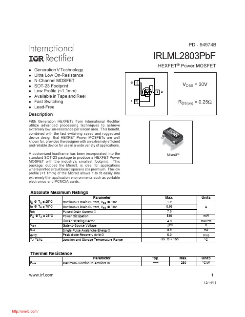
A customized leadframe has been incorporated into the standard SOT-23 package to produce a HEXFET Power MOSFET with the industry's smallest footprint. This package, dubbed the Micro3, is ideal for applications where printed circuit board space is at a premium. The low profile (<1.1mm) of the Micro3 allows it to fit easily into extremely thin application environments such as portable electronics and PCMCIA cards.
LTC3101EUF#PBF;LTC3101EUF#TRPBF;中文规格书,Datasheet资料

Battery Powered (Note 3) USB Powered (Note 3)
440 540
mA
440 540
mA
Maximum Duty Cycle
l 100
%
2
/
3101fb
LTC3101
ELECTRICAL CHARACTERISTICS The l denotes the specifications which apply over the full operating
APPLICATIONS
n Ultra-Portable Digital Video Cameras n Personal Handheld GPS Navigators n Portable Medical Instruments
LTC3101
Wide VIN, Multi-Output DC/DC Converter and
FEATURES
n Low Loss PowerPath™ Control: Seamless, Automatic Transition from Battery to USB or Wall Adapter Power
AK5357VTP-E2;中文规格书,Datasheet资料

13 PDN
14 DIF 15 CKS2 16 CKS0
I/O
Function
ห้องสมุดไป่ตู้
I Rch Analog Input Pin
I Lch Analog Input Pin
I Mode Select 1 Pin
Common Voltage Output Pin, VA/2 O
−40 ∼ +105°C
16pin TSSOP (0.65mm pitch)
Evaluation Board for AK5357
AINR
1
AINL
2
CKS1
3
VCOM
4
AGND
5
VA
6
VD
7
DGND
8
Top View
16 CKS0
15 CKS2
14 DIF
13 PDN
12 SCLK
11 MCLK
10 LRCK
2009/03
■ Ordering Guide
AK5357ET AK5357VT AK5357KT AKD5357
■ Pin Layout
[AK5357]
−20 ∼ +85°C
16pin TSSOP (0.65mm pitch)
−40 ∼ +85°C
16pin TSSOP (0.65mm pitch)
Vpp Vpp
2.7
3.0
3.3
VA=3V
-
1.8
-
Vpp
S/(N+D) (−1dBFS) VA=5V fs=48kHz
78