BZ-2RDT;中文规格书,Datasheet资料
CDZT2RA5.1B;CDZT2R5.1B;中文规格书,Datasheet资料

Limits 100 150 -55 to +150 -55 to +150
Unit mW 㷄 㷄 㷄
㪏㪅㪇㫧㪇㪅㪉
㪇㪅㪌
1/4
/
CDZ5.1B
Diodes
zElectrical characteristics (Ta=25qC)
Symbol TYP. CDZ 3.6B CDZ 3.9B CDZ 4.3B CDZ 4.7B CDZ 5.1B CDZ 5.6B CDZ 6.2B CDZ 6.8B CDZ 7.5B CDZ 8.2B CDZ 9.1B CDZ 10B CDZ 11B CDZ 12B CDZ 13B CDZ 15B CDZ 16B
㪫㪩㪘㪥㪪㪠㪜㪥㪫 㪫㪟㪘㪜㪩㪤㪘㪣㩷㪠㪤㪧㪜㪛㪘㪥㪚㪜㪑㪩㫋㪿㩷㩿㷄㪆㪮㪀
㪫㪜㪤㪧㪅㪚㪦㪜㪝㪝㪠㪚㪠㪜㪥㪚㪜㪑㱏㫑㩿㫄㪭㪆㷄㪀
㪈㪇㪇
㪩㫋㪿㩿㫁㪄㪺㪀
㪈㪇
㪤㫆㫌㫅㫋㪼㪻㩷㫆㫅㩷㪼㫇㫆㫏㫐㩷㪹㫆㪸㫉㪻 㪠㪤㪔㪈㫄㪘 㪠㪝㪔㪈㪇㫄㪘
㪈
㪈㫄㫊 㫋㫀㫄㪼 㪊㪇㪇㫌㫊
㪇㪅㪈 㪇㪅㪇㪇㪈
㪇㪅㪇㪈
㪇㪅㪈 㪈 㪈㪇 㪈㪇㪇 㪫㪠㪤㪜㪑㫋㩿㫊㪀 㪩㫋㪿㪄㫋㩷㪚㪟㪘㪩㪘㪚㪫㪜㪩㪠㪪㪫㪠㪚㪪
㪈 㪇 㪇㪅㪌 㪈 㪩㪜㪭㪜㪩㪪㪜㩷㪭㪦㪣㪫㪘㪞㪜㪑㪭㪩㩿㪭㪀 㪭㪩㪄㪚㫋㩷㪚㪟㪘㪩㪘㪚㪫㪜㪩㪠㪪㪫㪠㪚㪪 㪈㪅㪌
㪌㪅㪊 㪫㪸㪔㪉㪌㷄 㪠㪱㪔㪌㫄㪘 㫅㪔㪊㪇㫇㪺㫊
㪈 㪇㪅㪐 㪫㪸㪔㪉㪌㷄 㪭㪩㪔㪈㪅㪌㪭 㫅㪔㪊㪇㫇㪺㫊
㪈㪇㪇 㪐㪇 㪫㪸㪔㪉㪌㷄 㪽㪔㪈㪤㪟㫑 㪭㪩㪔㪇㪭 㫅㪔㪈㪇㫇㪺㫊
㪩㪜㪭㪜㪩㪪㪜㩷㪚㪬㪩㪩㪜㪥㪫㪑㪠㪩㩿㫅㪘㪀
/
Appendix
Notes
No technical content pages of this document may be reproduced in any form or transmitted by any means without prior permission of ROHM CO.,LTD. The contents described herein are subject to change without notice. The specifications for the product described in this document are for reference only. Upon actual use, therefore, please request that specifications to be separately delivered. Application circuit diagrams and circuit constants contained herein are shown as examples of standard use and operation. Please pay careful attention to the peripheral conditions when designing circuits and deciding upon circuit constants in the set. Any data, including, but not limited to application circuit diagrams information, described herein are intended only as illustrations of such devices and not as the specifications for such devices. ROHM CO.,LTD. disclaims any warranty that any use of such devices shall be free from infringement of any third party's intellectual property rights or other proprietary rights, and further, assumes no liability of whatsoever nature in the event of any such infringement, or arising from or connected with or related to the use of such devices. Upon the sale of any such devices, other than for buyer's right to use such devices itself, resell or otherwise dispose of the same, no express or implied right or license to practice or commercially exploit any intellectual property rights or other proprietary rights owned or controlled by ROHM CO., LTD. is granted to any such buyer. Products listed in this document are no antiradiation design.
MMDF2P02ER2G;中文规格书,Datasheet资料
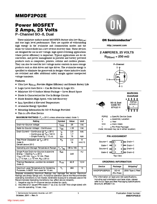
TJ, Tstg EAS
RqJA
−55 to 150 245 62.5
°C mJ
°C/W
Maximum Lead Temperature for Soldering
TL
Purposes, 0.0625″ from case for 10 sec.
Drain−1 Drain−1 Drain−2 Drain−2
ORDERING INFORMATION
Device
Package
Shipping†
MMDF2P02ER2G SO−8 2500 Tape & Reel (Pb−Free)
†For information on tape and reel specifications, including part orientation and tape sizes, please refer to our Tape and Reel Packaging Specifications Brochure, BRD8011/D.
RDS(on)
gFS
Ciss Coss Crss
td(on) tr
td(off) tf
td(on) tr
td(off) tf QT Q1 Q2 Q3
VSD trr ta tb QRR
Min
Typ
Max Unit
25
−
−
2.2
Vdc
−
−
mV/°C
mAdc
−
−
1.0
−
−
10
−
−
100 nAdc
4831.2220;中文规格书,Datasheet资料

Technical SpecificationSchurter’s range of "Audio, DC and DIN Connectors" offers a cost effective solution for a wide range of applications.RangeThe range features 2.5mm, 3.5mm and 6.3mm Audio plugs and sockets.Low voltage DC plugs and sockets rated at 12V DC 0.5A for 5.5x2.1mm/5.5x2.5mm, 13.5V DC 2A for JSBP4 and 18V DC 2A for JSBP5.Miniature circular DIN plugs and sockets 3 to 8 pole.Plugs for all these ranges are rewirable and the sockets are fitted with solder or PCB tabs.Manufacturing Standards and Compatibility These cost effective connectors are designed and manufactured using dry assembly techniques. They comply with Japanese and Asian standards and are widely compatible to connectors fitted on consumer and industrial products, used worldwide.ApplicationsThese include connectors for low voltage power supplies, audio input and output, connections to controllers and transducer for game consoles, audio and video entertainment systems, musical instruments, amplifiers, transceiver’s, cleaning equipment, computer game cards, lap tops, printers, mobile / cordless phones, alarm systems, fitness machines.SpecificationThe specification shows operating characteristics.As with any connection products, to ensure customer satisfaction mating parts should be supplied from one source.For the combination chart please see Page 24.Technische SpezifikationSchurter’s Sortiment an “Audio, DC und DIN Stecker”bietet eine kostengünstige Alternative für ein weites Spektrum von Anwendungen.SortimentDas Sortiment umfasst 2.5mm, 3.5mm und 6.3mm Audio Stecker und Steckdosen.Niederspannungs DC Stecker und Steckdosen bis zu12V DC 0.5A für 5.5x2.1mm/5.5x2.5mm, 13.5V DC 2A für JSBP4 und 18V DC 2A für JSBP5.Miniatur DIN Stecker und Steckdosen von 3 bis 8 Pole.Stecker für alle Sortimente sind verkabelbar und die Steckdosen sind bestückt mit Löt oder PIN Anschlüssen.Herstellung und KompatibilitätDiese kostengünstigen Stecker sind entwickelt und hergestellt mit einer trockenen Montagetechnik (nicht Einspritz-Technik).Sie entsprechen Japanischen und Asiatischen Normen und sind kompatibel mit den meistenStecker/Steckdosen von Konsumer- und Industrie Produkten, weltweit.AnwendungenNiederspannungs Stromversorgung, Audio Ein- und Ausgänge, Verbindungen zu Regelgeräten und Wandlern/Verstärker für Spielgeräte, Audio- und Video Geräten, Musikinstrumente, Senderempfänger, Reinigungsgeräte, Computerspiele, Laptops, Drucker, Natels, Alarm Systeme und Fitnessgeräte.SpezifikationDie Spezifikation zeigt die Einsatz Charakteristik auf. Wie mit allen Steckverbindungen, für einen optimalen Wert, sollte man die Stecker und Steckdosen von der gleichen Quelle beziehen.Für die Kombinations Möglichkeiten konsultieren sie bitte Seite 24.T e c h n i c a l S p e c i f i c a t i o nT e c h n i s c h e S p e z i f i k a t i o n78.3Cable max.4.02.5Technical SpecificationSee Page 7 for complete technical specification and Page 24 for possible combinations.Technische Spezifikation Siehe Seite 7 für die vollständige technische Spezifikation undKombinationen.A u d i o C o n n e c t o r sA u d i o S t e c k e r9.5Cable max.4.02.5Cable max.4.012.019.51.0 1.482.5w w w.s c h u r t e r.c o m7.24.33.95.09.62.68.25.010.82.69.04.35.011.05.02.513.02.69.51.5Cable max.4.010.4Cable max.4.0 2.511.09.0Technical Specification See Page 7 for complete technical specification and Page 24 for possible combinations.Technische Spezifikation Siehe Seite 7 f ür die vollst ändige technischeSpezifikation und Seite 24 f ür m öKombinationen.A u d i o C o n n e c t o r s A u d i o S t e c k e r2.58.5 Cable max.3.0 Cable max.4.012.019.51.01.0102.52.5m m /3 P o l ew w w.s c h u r t e r.c o m2.63.06.58.02.62.74.010.04.02.62.85.02.35.010.4Cable max.4.0 1.59.011分销商库存信息: SCHURTER 4831.2220。
VDZT2R6.2B;中文规格书,Datasheet资料
Diodes
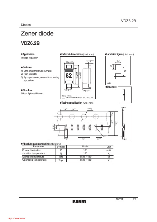
Zener diode
VDZ6.2B
zApplication Voltage regulation zExternal dimensions (Unit : mm)
㩷
㪇㪅㪍㫧㪇㪅㪇㪌 㪇㪅㪈㪊㫧㪇㪅㪇㪊
zLand size figure (Unit : mm)
㪇㪅㪌 㪇㪅㪌
TYPE VDZ̛12B VDZ̛13B VDZ̛15B VDZ̛16B VDZ̛18B VDZ̛20B VDZ̛22B VDZ̛24B VDZ̛27B VDZ̛30B VDZ̛33B VDZ̛36B ̛
㪫㪰㪧㪜䇭㪥㪦㪅
25 35 45 55 65 75 85 95 A5 C5 E5 F5 䇭
Rev.B 2/4
/
VDZ6.2B
Diodes
ቤተ መጻሕፍቲ ባይዱ㪈㪇
㪈
㪱㪜㪥㪜㪩㩷㪚㪬㪩㪩㪜㪥㪫㪑㪠㫑㩿㫄㪘㪀
㪇㪅㪈
㪋㪅㪎 㪇㪅㪇㪈 㪋㪅㪊 㪊㪅㪐 㪊㪅㪍
㪌㪅㪈 㪌㪅㪍 㪍㪅㪉 㪍㪅㪏 㪎㪅㪌 㪐㪅㪈 㪈㪇 㪏㪅㪉 㪈㪈 㪈㪉 㪈㪊 㪈㪌 㪈㪍 㪈㪏 㪉㪇 㪉㪉 㪉㪋 㪉㪎 㪊㪇 㪊㪊 㪊㪍
㪇㪅㪇㪇㪈 㪇 㪌 㪈㪇 㪈㪌 㪉㪇 㪱㪜㪥㪜㪩㩷㪭㪦㪣㪫㪘㪞㪜㪑㪭㫑㩿㪭㪀 㪭㫑㪄㪠㫑㩷㪚㪟㪘㪩㪘㪚㪫㪜㪩㪠㪪㪫㪠㪚㪪 㪉㪌 㪊㪇 㪊㪌 㪋㪇
zType No.
TYPE VDZ̛3.6B VDZ̛3.9B VDZ̛4.3B VDZ̛4.7B VDZ̛5.1B VDZ̛5.6B VDZ̛6.2B VDZ̛6.8B VDZ̛7.5B VDZ̛8.2B VDZ̛9.1B VDZ̛10B VDZ̛11B
TYPE䇭NO.
62 72 82 92 A2 C2 E2 F2 H2 J2 L2 05 15
SF2038B-2;中文规格书,Datasheet资料

Notes:1.Unless noted otherwise, all specifications apply over the operating temperature range with filter soldered to the specified demo nstration board with impedance matching to 50 Ω and measured with 50 Ω network analyzer.2.Unless noted otherwise, all frequency specifications are referenced to the nominal center frequency, fc.3.Rejection is measured as attenuation below the minimum IL point in the passband. Rejection in final user application is depende nt on PCB layout and external impedancematching design. See Application Note No. 42 for details.4."LRIP" or "L" after the part number indicates "low rate initial production" and "ENG" or "E" indicates "engineering prototypes."5.The design, manufacturing process, and specifications of this filter are subject to change.6.Tape and Reel Standard ANSI / EIA 481.7.Either Port 1 or Port 2 may be used for either input or output in the design. However, impedances and impedance matching may va ry between Port 1 and Port 2, so thatthe filter must always be installed in one direction per the circuit and international patents may apply.9.RFM, stylized RFM logo, and RF Monolithics, Inc. are registered trademarks of RF Monolithics, Inc.10.©Copyright 1999, RF Monolithics Inc.11.Electrical CharacteristicsCharacteristicSym Notes MinTyp Max Units Nominal Center Frequency f C176.500MHz PassbandInsertion Loss IL 10.012.0dB 1dB Passband BW 1112.514.0MHz 15dB Bandwidth BW 1516.818.0MHz 30dB Bandwidth BW 3018.019.2MHz Amplitude Ripple over fc ±6.25 MHz 0.70 1.3dB P-P Group Delay Variation over fc ±6.25 MHz G DV40150ns P-PRejection 50 to 64.44 MHz1, 34046dB64.44 to 66.70 MHz -40 to 85°C 364164.44 to 66.70 MHz 85 to 105°C3086.30 to 87.54 MHz *304487.54 to 91.50 MHz 314491.50 to 100 MHz4047Operating Temperature Range T A 1-40+105°C Frequency Coeffieient FTC -87ppm/°CDifferential Input 175 ohms Differential Output 180 ohmsCase Style6SMP-03 7 x 5 mm Nominal FootprintLid Symbolization (YY=year, WW=week, S=shift) See note 4RFM SF2038B YYWWS•Designed for SDARS IF Receiver •Low Insertion Loss• 5.0 X 7.0 mm Surface-Mount Case•Differential or Single Ended Input and Output •Complies with Directive 2002/95/EC (RoHS)Absolute Maximum RatingsRatingValue Units Maximum Incident Power in Passband +10dBm Max. DC voltage between any 2 terminals 30VDC Storage Temperature Range (with tape & reel)-40 to +85°C Storage Temperature Range (without tape & reel)-50 to +125°CMax Soldering Profile265°C for 10 s 76.500 MHzSAW FilterSF2038B-2Pb*At low temperature extreme -40°CReference DesignatorValue C115 pF C215 pF L1270 nH L2270 nH C327 pF C427 pFWideband SAW Matching ValuesWideband SAW Matching CircuitMatching Circuit and Matching Component Values Used in G3 Sirius Radios(Refer to Sirius Radio G3 Chipset Application Note, Doc. #RX000104-B, Sec. 4.2.2)Matching Circuit and Matching Component Values Used on Filter Demo BoardC1C2L1RFM SF2038BC4L2SF2038B 76.500 MHz C1 = 22pF C2 = 22pF L1 = 220nH L2 = 270nH C3 = 22pF C4 = 22pFZinput 1:3Transformer150ΩZoutput 4:1Transformer200ΩC3SMP-03 CaseRecommended PCB FootprintCase Dimensions Dimensionmm Inches Min Nom Max Min Nom Max A 6.807.007.200.2680.2760.283B 4.80 5.00 5.200.1890.1970.205C 1.65 2.000.0650.079D .470.60.730.0190.0240.029E 2.41 2.54 2.670.0950.1000.105H 0.87 1.0 1.130.0340.0390.044J 4.87 5.00 5.130.1920.1970.202K 2.87 3.00 3.130.1130.1180.123P1.141.271.400.0450.0500.055MaterialsSolder Pad Termination Au plating 30 - 60 uInches (76.2-152 uM) over 80-200 uInches (203-508 uM) Ni.Lid Fe-Ni-Co Alloy Electroless Nickel Plate (8-11% Phosphorus) 100-200 uInches Thick Body Al 2O 3 CeramicPb FreeElectrical ConnectionsConnectionTerminalsPort 1Input or Return 10Return or Input 1Port 2Output or Return 5Return or Output 6GroundAll others Single Ended Operation Return is ground Differential OperationReturn is hotCH10-Terminal Ceramic Surface-Mount Case7 x 5 mm Nominal FootprintTape and Reel Specifications“B “Nominal Size Quantity Per ReelInchesmillimeters7178500133302000USER DIRECTION OF FEEDCOMPONENT ORIENTATION and DIMENSIONSCarrier Tape DimensionsAo 5.5 mm Bo 7.5 mm Ko 2.0 mm Pitch 8.0 mm W16.0 mmPIN #1分销商库存信息: RFMSF2038B-2。