Guidelines for Proper Wiring of an RS-485 (TIA EIA-485-A) Network
如何正确使用电英文作文

如何正确使用电英文作文英文回答:Using electricity safely is crucial for preventing accidents and ensuring the well-being of individuals and the community. Here are some essential guidelines for handling electricity safely:Electrical Appliances: Always ensure that electrical appliances are in good condition and free from any visible damage. Check for frayed cords, loose connections, or exposed wires before using them.Plugs and Sockets: Properly insert plugs into sockets, ensuring a secure connection. Avoid overloading sockets by connecting too many appliances to a single outlet.Water and Electricity: Never use electrical appliances or touch electrical outlets with wet hands or while standing in water. Water is an excellent conductor ofelectricity and can pose a severe electrical hazard.Outdoor Use: When using electrical equipment outdoors, use extension cords specifically designed for outdoor use. Ensure they are protected from moisture and exposure to elements.Lightning Storms: During lightning storms, avoid using electrical appliances and unplug sensitive electronics to prevent damage from power surges.Electrical Fires: In case of an electrical fire, immediately disconnect the power source by turning off the circuit breaker or fuse box. Use a Class C fire extinguisher to put out the flames.Electrical Safety Education: Educate yourself and your family about electrical safety. Familiarize yourself with the location of circuit breakers and fuse boxes in your home.Regular Inspections: Regularly inspect electricalsystems, wiring, and appliances for any signs of damage or wear. Promptly address any issues to prevent potential hazards.Professional Electricians: For complex electrical repairs or installations, seek the assistance of a qualified electrician. Do not attempt DIY electrical work unless you have the necessary expertise.Power Outages: During power outages, turn off or unplug appliances to prevent damage from sudden power surges when electricity is restored.中文回答:用电安全。
Guidelinesforcor...
Guidelines for correct electrical supply & testing for lifts in service - including builders lifts.PurposeTo provide practical guidance on Prescribed Inspection and Testing requirements for passenger lifts.To ensure passenger lifts installed in commercial building structures, which are available for passenger use, are provided with electrical supply and protective devices designed for safe operation.ApplicationThese guidelines apply to a lift Installer, electricians, builders and building owners in control of installations where lifts are used to convey passengersBackgroundPassenger lifts used in all Victorian commercial installations are considered to be a safety service as defined in Australian/New Zealand Wiring Rules. As such they are to be installed to conform to requirements of AS/NZS 3000:2007 & AS1735.2 prior to use for conveying passengers. Often in early stages of construction passenger lifts are commissioned to be used as a lift to convey persons and materials during the remainder of the construction stage. This type of passenger lift is commonly termed as a ‘builders lift’.Where a passenger lift is to be used as a ‘builders lift’ it must meet all requirements for the testing and commissioning to ensure performance and safety mechanisms are verified. Passenger lifts, being a safety service, are required to have prescribed electrical installation work inspected by a licensed electrical inspector prior to the lift being placed in service. This is a requirement of Electricity Safety (Installation) Regulations 2009.Inspection of electrical installation workAn electrician who is responsible for the carrying out of prescribed electrical installation work must ensure that the work is inspected by a licensed electrical inspector in accordance with the regulations before the electrical installation is connected to the electricity supply, or if the electrical circuits or electrical equipment handled in the course of the work were not disconnected from the electricity supply, before the work is first used after it is completed. An electrician must ensure that the licensed electrical inspector inspecting any prescribed electrical installation work is not a person who is employed by the electrician; or a related body corporate of the electrician.Energy Safe Victoria requirementsThe passenger lift shall pass all requirements of the Prescribed Inspection before handover for use.Recommended items to be inspected for verification∙All mains and sub mains cables from the point of supply through to the lift switchboard associated with the lift installation to ensure appropriate WS rating is provided∙Basic protection (protection against direct contact with live parts), e.g. insulation and enclosure∙Fault protection (protection against indirect contact with exposed conductive parts)∙Protection against hazardous parts, e.g. enclosure, guarding or screening of flammable materials, hot surfaces and parts that may cause physical injury∙Protection against spread of fire, e.g. penetration of fire barriers∙Motor room door installation and labelling∙General condition of the electrical equipment, e.g. signs of damage that could impair safe operation, disconnection of unused electrical equipmentMains∙Identification of cable cores∙Current carrying capacity of mains∙Voltage drop, e.g. size and length of conductors and load∙Underground installation conditions, e.g. enclosure, depth of burial, mechanical protection∙Connection of wiring∙Protection against external influencesSwitchboards∙Location, e.g. access and egress, not in restricted location∙Protective devices, e.g. selection and setting of adjustable protective devices for compliance with over current protection, arc fault protection and discrimination∙Isolating devices, e.g. main switches∙Connecting devices, e.g. neutral bars, earth bars and active links∙Connection and fixing of wiring and switchgear∙Identification and labelling of electrical equipment, and∙Protection against external influences, e.g. mechanical damageDefinitionsLicensed Electrical Inspector means a person holding an inspector's licence underthe Electricity Safety (Installations) Regulations 2009Passenger lift in this document means an electrically controlled lift that is capable of conveying passengers, but does not include a lift installed in a single private residence in accordance with AS1735.18Safety service has the same meaning as it has in the Australian/New Zealand Wiring Rules AS/NZS 3000:2007Prescribed electrical installation work. For the purposes of Electricity Safety Act 1998 section 45, prescribed electrical installation work means work on all or part of any of the following electrical installations if they are ordinarily operated at low voltage or a voltage exceeding low voltage— circuit protective devices, switchgear, control gear, wiring systems and accessories (other than fire detection and alarm systems) installed to provide control and protection of passenger liftsVerification— All measures by means of which compliance of the electrical installation with the relevant requirements of AS/NZS 3000 and AS/NZS3017:2000 is checked. Further informationElectricity Safety Act 1998Electricity Safety (Installation) Regulations 1999Acts & Regulations are available from Information Victoria on 1 300 366 366 or order on line at .au. They can be viewed by visiting the ESV web site at .auAustralian/New Zealand Wiring Rules means AS/NZS 3000, Australian/New Zealand Standard, "Electrical installations", as published or amended from time to timeAS/NZS 3017:2000 means AS/NZS 3017:2000, Australian/New Zealand Standard, Electrical installations – Verification guidelinesAS1735.2 means AS1735.2, Australian/New Zealand Standard, "Lifts, escalators and moving walks – General requirements", as published or amendedfrom time to timeStandards Australia publications can be obtained by contacting Standards Australia on 1 300 654 646 or by visiting the web site at .auThis guidance material has been prepared using current and best information available to Energy Safe Victoria. You should check the legislation referred to in this document and make your own judgement about what action you need to undertake to ensure compliance with the law.。
StandardsandGuidelines

DocumentationSTANDARDS AND GUIDELINESGuidelines for Documentation inthe Gastrointestinal Endoscopy SettingDisclaimerThe Society of Gastroenterology Nurses and Associates, Inc. assumes no responsibility for the practices or recommendations of any member or other practitioner, or for the policies and proceduresof any practice setting. The nurse and associate function within the limitations of licensure, statenurse practice act, and/or institutional policy.This guideline is based on current understanding and practice in the field. Eachgastrointestinal/endoscopy unit is responsible for establishing its own documentation proceduresand for creating its own forms, allowing for the differences in operation of each unit. The sampleforms illustrated herein are not necessarily suited for any unit other than the unit that developedeach form. They are printed here with the permission of the contributing facilities.PrefaceDocumentation development is guided by the use of the nursing process (assessment, planning, intervention and evaluation) to establish an individualized plan of care for the patient while in the endoscopy unit. This guideline is intended to provide direction for individual endoscopy units in establishing consistent patient care documentation. These documentation guidelines meet requirements for patients receiving sedation. A reduced requirement for documentation may apply dependent onyou institutional policy for non-sedated patients. Documentation should clearly and uniformly record details that closely describe situations or events occurring to patients undergoing endoscopy or related procedures. This guideline incorporates Centers for Medicare and Medicaid Services (CMS) requirements and Joint Commission on Accreditation of Healthcare Organizations (JCAHO) recommendations. Various members of the healthcare team may be responsible for documenting specific items in the patient record.In order to provide information that is easily adaptable to each patient care environment, theguideline is divided into three major components: Pre-Procedure, Procedure and Post-Procedure. The intent of the guideline and the accompanying outline is to provide information and criteria that canbe selected in formulating an individualized document that meets the needs and requirements to conform to institutional policy and to the particular endoscopy setting.Definition of TermsFor the purpose of this document, the following terms are defined:Vital signs: temperature, heart rate, respiratory rate, blood pressure, pain, and oxygen saturation assessment.DocumentationJCAHO: Joint Commission for Accreditation of Healthcare Organizations.CMS: Centers for Medicare and Medicaid Services.AAAHC: Accreditation Association for Ambulatory Health Care.Pre-Procedure Phase: the period of time prior to the beginning of the procedure.Procedure Phase: from the initiation of sedation and analgesia, when used, or the initial step of an invasive procedure, until completion of the diagnostic or therapeutic intervention.Post-Procedure Phase: from the completion of the diagnostic or therapeutic intervention until the patient leaves the facility.Section 1:Pre-Procedure PhaseAn age-specific patient assessment is performed and documented by a registered nurse. The assessment factors should include physical, psychosocial, current medications, treatment, and previous medical, anesthetic and drug history. Review of the patient’s symptoms and history will supply any pertinent information to be documented.All documentation should include time of performance and name of person performing the assessment or intervention. The frequency of the assessment is determined byinstitutional/departmental policy, the patient condition, the physician and/or the registered nurse. JCAHO recommendations and CMS requirements for the Pre-Procedure Phase are included in the following:1. Time of assessment2. Telemetry, if applicable.3. Oxygen saturation if sedation or analgesia is anticipated.4. CO2 monitoring (optional)5. Level of consciousness/mental status6. Disposition of patient valuables (i.e. glasses, jewelry,etc.)7. Baseline pain assessment using institutionally approved pain scale with identification ofarea, duration and type of pain8. Warmth, dryness and color of skin9. NPO status10. Bowel prep compliance (if applicable)11. Current medications and time of last dose(s) including aspirin, non-steroidal anti-inflammatory drugs, anticoagulants, sleeping medications, tranquilizers, over-the-counter drugs, herbal agents or illicit drugs.12. Allergies and reactions to medication, food, contrast or latex including OTC and herbals13. Presence of removable dental appliances, loose teeth, glasses/contact lenses, hearing aids14. Presence of prosthetic devices (e.g., hip replacement, valves)15. Airway assessment (e.g., jaw and neck mobility)16. Intravenous line: type, site, inserted by, rate of IV solution or presence of venous accessdevice17. Pregnancy status18. Physical assessment appropriate to the patient’s age, individual needs, and procedure to beperformed19. Labs or previous procedures results (if applicable)Documentation20. Patient concerns21. Emotional status, psychological, spiritual, cultural status22. Assessment for potential abuse23. Educational needs assessment with identification of barriers to learning24. Known significant medical diagnoses and conditions including current status of infectiousdisease/exposure, physical disabilities, and conditions25. Known significant surgical and invasive procedures, history of complications or reactions toprevious sedation, analgesia, or general anesthesia26. Validation of correct patient/correct procedure27. Admitting registered nurse signature/timeSection 2:Procedure PhaseEvery patient undergoing a diagnostic or therapeutic, or invasive procedure requires monitoring by a registered nurse or other qualified personnel. Whatever method is employed, documentation should include event, intervention (if necessary) and outcome. Each facility must comply with applicable regulations and guidelines, including state regulations, JCAHO guidelines, CMS requirements, andthe facility’s standards for monitoring of patients. JCAHO recommendations and CMS requirements forthe Procedure Phase are included in the following:1. Vital signs2. Telemetry, if applicable3. Baseline and ongoing pulse oximetry is required for patients undergoing sedation andanalgesia.4. CO² (optional)5. Level of consciousness/mental status6. Continuous pain assessment using institutional approved pain scale with documentedresponse to intervention7. Warmth, dryness, and color of skin8. Procedure(s) performed9. Physician(s), registered nurse(s) and support staff involved in the procedure10. Name and dosage of all drugs and agents used (including oxygen), time, route ofadministration, by whom, and patient’s response11. Type and amount of all fluids administered (including blood and blood products)12. Equipment/accessories used (i.e. cautery, laser,etc.)13. Implantable devices (i.e.stents, tubes, etc.)14. Unusual events, interventions and outcomes15. Patient status at the end of procedure16. Type of specimen(s) obtained and disposition17. Post-Procedure findings18. Signature(s) required19. “Time Out” initiated by the physician to confirm the right patient/right procedureDocumentationSection 3:Post-Procedure PhaseThe frequency of the assessment is determined by institutional/departmental policy, the physician and/or the registered nurse. JCAHO recommendations and CMS requirements for the Post-Procedure Phase are included in the following:1. Time of arrival in post-procedure area2. Vital signs3. Pulse oximetry is required until return to pre-procedure baseline for patients who receivedsedation and analgesia.4. Continuous pain assessment using institutional approved pain scale with documentedresponse to intervention5. Level of consciousness/mental status6. Warmth, dryness and color of skin7. Name and dosage of all drugs used (including oxygen), time, route of administration, bywhom, and patient’s response8. IV fluids administered and/or discontinued including blood and blood products9. Unusual events, interventions, and outcomes10. Physical assessment appropriate to age, patient needs, and procedure performed11. Disposition of patient (hospital room, home, x-ray, etc.), and with whom12. Report given to subsequent caregiver13. Mode of transportation (ambulatory, stretcher, wheelchair, etc.)14. Name of person responsible for outpatient at discharge15. Age specific discharge instructions and educational materials given to outpatient and/oraccompanying adult, who verbalizes or demonstrates understanding and signs form.16. Discharge criteria applied17. Time of discharge18. Signature of discharge nurse19. Discharge instructions per institution policy to include follow-up and specific patient orderswritten by the physician.ConclusionBy combining the JCAHO recommendations and CMS requirements for documentation along with published data and input gathered from the membership, SGNA anticipates that these recommendations will provide guidance to each endoscopy unit staff in establishing a comprehensive institutional documentation policy.ReferencesAmerican Society of Anesthesiologists. (2001). Updated practice guidelines for sedation and analgesia by non-anesthesiologists. [Practice guideline]. Park Ridge, IL: Author.Documentation Committee on Drugs of the American Academy of Pediatrics. (1992). Guidelines for monitoring and management of pediatric patients during and after sedation for diagnostic and therapeuticprocedures. Pediatrics, 89, 1110-1115.Health Care Finance Administration. (1993). Generic Quality Screen Guidelines, Exhibit 37.Washington, DC: Author.Joint Commission on Accreditation of Healthcare Organizations. (2003). Comprehensive Accreditation Manual for Hospitals: The Official Handbook. Oakbrook Terrace, IL:Author.Kost, M. (1999). Conscious sedation: Guarding your patient against complications. Nursing. 29 (4): 34-39.Standards of Practice Committee of the American Society for Gastrointestinal Endoscopy. (2002).Sedation and monitoring of patients undergoing gastrointestinal endoscopic procedures.Gastrointestinal Endoscopy, 2, 626-629.Society of Gastroenterology Nurses and Associates, Inc. (2000). Guidelines for nursing care of the patient receiving sedation and analgesia in the gastrointestinal setting. [Guideline].Gastroenterology Nursing. 23:125-129.AcknowledgmentsFirst edition 1989, revised 2003.Prepared by the Education Committee of the Society of Gastroenterology Nurses and Associates, Inc. (SGNA) chaired by Trina Van Guilder, RN,BSN,CGRN.Adopted by the Society of Gastroenterology Nurses and Associates, Inc. Board of Directors 2003. Published as a service to members by the Society of Gastroenterology Nurses and Associates, Inc. Copyright © 2003, Society of Gastroenterology Nurses and Associates, Inc.DocumentationOutline for Form PreparationThe following outline is included to ease the preparation of a form to be used for the acquisition of data, procedure and post-procedure documentation and statement of patient’s dispositionI.Pre-Procedure PhaseScheduled ProcedureB. Patient identification1. Demographic dataa. Nameb. Date of birthc. Unique patient identification numberd. Phone number2. Physician3. Referring physician4. Time of arrival5. Communication barrier6. Impairments7. Responsible adult fordischarge/accompanied byC. Health History1. Past procedure(s)2. Previous problems with anesthesia orsedation3. Chief complaint4. Present illness5. Allergies including reactions: food,medication, latex6. Current medication, time of last dose(s)7. Level of consciousness/ mental status8. Level of comfort9. Bowel preparation10. NPO status11. Baseline vital signs and pulse oximetry12. Weight in pounds/kilogramsAirway assessment (neck and jaw mobility, dentition)D. Medical History1. Heart disease, pacemaker, implantedcardioverter defibrillator, dysrhythmias,valvular heart disease2. Hypertension3. Lung/breathing problems (e.g., asthma,COPD, sleep apnea)4. Liver disease (e.g., jaundice, hepatitis,cirrhosis)5. Pancreatic disorders (e.g., pancreatitis,6. rders (e.g., seizures,disease10.nia, IBD/IBS, diverticulosis,13.sing institutional scale, duration, location)rE. Surgisthetic devices (e.g.,stents, valves, joint replacements)sF. Family Historycancer2. olyps3. IBDdiabetes)Neurological disoCVA, ALS, MS)7. Kidney8. CancerBleeding or blood di9. sorders, includingtransfusion historyGI problems (e.g., peptic ulcer disease,hiatal herpolyps)11. Arthritis12. Pregnancy statusGlaucoma14. Pain (u15. Othecal1. Implanted pro2. GI surgerie1. ColonPDocumentationG. Social Historye.g., ETOH, illicitrugs)H. Venous Access Devicee used Solution and rate/flushResultsJ. P 4. Methods (e.g., pamphlet, video) gM. Presence and Disposition of Appliances(e.g., dentures, hearing aids, contacts,. Vulnerable Adult yes/no; Social Servicesgnaturease 1. Substance abuse (d 2. Smoking history1. Time started2. Site3. Type of devic . 45. Inserted by I. Laboratory Test atient Teaching1. Patient knowledge of procedure2. Barriers to learning3. Interventions to learning barriers 5. Demonstrates understandin K. Pre-Procedure Nursing NotesL. Informed Consent Obtainedglasses) N Notified yes/noO. Admitting Nurse SiII. Procedure PhProcedure TimeB. Validation of correct patient/correct e (“Time out”)B. S rse(s) Support staffC. Medication (including oxygen)ed Administered by response D. V ns of skin Level of consciousness/mental status sponse E. E 3. The dingin condition c. : settings,e. evice: purpose (e.g.,ding tubes: size,, lot number Dilators: size, type 4. amples). Documentation of anyindwelling devices left in patientStarted Completedprocedur taffPhysician(s)Registered nu Technicians1. Time administer2. Dosage/liters3. Route/method . 45. Patientital Signs1. Blood pressure, heart rate, respiratio2. Oxygen saturation3. Warmth, color and dryness . 45. Level of comfort/requipment/Accessories1. Endoscope2. Monitoring equipmentrapeutic modalities (examples)a. Cautery: type, setting, groun pad site & pre/post skb. Laser: type, settings, safetyprocedures followedArgon plasma coagulator flow rate, grounding pad site &pre/post skin conditiond. Band ligators: number placed Injection d sclerotherapy, tattooing, contrast medium)f. PEG/PEJ, stents, fee type, manufacturer . g h. Other (e.g., snare)Diagnostic modalities (ex a. Probes (e.g, pH, rectal) b. Manometry catheterc. Other (e.g., biopsy forceps)dDocumentation. FluoroscopyG. Imaging(e.g., videotape, photography)H. S y icrobiology Procedure Performed and Post-ProcedureJ. Nursing Observation Notestions andre3. ost-procedure assessment beforeK. Nurse/Staff Signature(s)F 1. Time 1. Methodpecimens1. Biopsy2. Cytolog3. M4. OtherI.Diagnosis 1. Unusual events, interven outcomes2. Toleration of procedu P transfer to recoveryPhysician’s signatureIII. Post-Procedure PhaseA. Time of Arrival to Post-Procedure Area. Vital Signs and oxygen saturation fortal Status t/ResponseE. Ven d (including bloodts) Time discontinued 3. Condition of siteB patients who received sedationC. Level of Consciousness/MenD. Level of Comfor ous Access1. Total amount infuse and blood produc . 2 F. Medications1. Time administered2. Dosage3. Route4. Administered by5. Patient responseNote: Usage of only acceptable medication names and dosage abbreviations.G. Oral Fluid ToleranceH. Report Given to Subsequent CaregiverI. Discharge InstructionsGiven by Given toVerbalizes or demonstrates understanding Signature of patient and/or accompanyingadultDischarged according to criteria or byphysician discharge orderJ. DispositionDestinationAccompanied by (name of individual) Mode of transportationK. Time of DischargeL. Nursing Observation NotesUnusual events, interventions and outcomesM. Discharge Nurse SignatureDischarge Instructions to OutpatientsA. Type of Procedure PerformedB. Activity1. Normal2. Restrictions (e.g., driving, operatingmachinery, working)C. DietNormalModificationsa. Special diet instructionsDocumentationF. Medication Instructionsb. Fluids Restrictions NPO (e.g., untilanesthetic worn off)1. Continue2. DiscontinueAvoidance of alcohol (state number ofhours)3. New medications prescribed4. Interactions of medications with foodand other drugs D. Post-Procedure Complication Symptoms 1. List symptoms specifically (e.g.,abdominal pain, fever, evidence of bleeding)G. Specimen ResultsMethod for obtaining results (e.g., callphysician’s office)2. Instructions for notifying physician orobtaining emergency assistance (include physician office/answering service phone numbers) H. Additional Pertinent InstructionsFollow-up visit with physician Referrals, if appropriateE. Instructions for Symptoms and SensationsExpected as Normal, and RemediesSore throat - throat lozenges, gargle withwarm water, etc.Redness at IV site - apply warm compress,etc.Gaseous discomfort - belching, passingflatusI. Signatures1. Patient and/or accompanying adult2. Nurse discharging the patientA copy of the discharge instructions or written documentation is given to the patient and one is kept in the patient’s chart.。
2015年 Форд Тауrus 快速参考指南说明书

2015 T au r u sQuick Reference GuideThis Quick Re fe re nce Guide is not inte nde d to re place your ve hicle Owne r’s Manual which contains more de taile d information conce rning the fe ature s of your vehicle, as well as important safety warnings designed to help reduce the risk of injury to you and your passengers. Ple ase re ad your e ntire Owne r’s Manual care fully as you be gin le arning about your ne w ve hicle and re fe r to the appropriate chapte rs whe n que stions arise. All information containe d in this Quick Re fe re nce Guide was accurate at the time of duplication. We reserve the right to change features, operation and/or functionality of any vehicle specification at any time. Your Ford dealer is the be st source for the most curre nt information. For de taile d ope rating and safe ty information, ple ase consult your Owner’s Manual.June 2015 Third PrintingQuick Reference GuideTaurusLitho in U.S.A.Ford Customer Relationship Center 1-800-392-3673 (FORD)(TDD for the hearing impaired: 1-800-232-5952)@FordServiceFord Customer Relationship Centre 1-800-565-3673 (FORD)ford.ca@FordServiceCAFG1J 19G217 AATABLE OF CONTENTSINSTRUMENT PANEL4–5GETTING STARTEDWITH YOUR SYNC SYSTEM 6–7SYNC WITH MYFORD TOUCH 8–10COMFORT 11–13CONVENIENCE 14–15FUNCTION 16–17ESSENTIAL INFORMATION 18–19 ENTERTAINMENT NAVIGATION**BASIC COMMANDSPHONECLIMATE**W A R N I N Gwhile driving.ford.caSOON LIGHT Lights briefly when you switch on the ignition. If it remains on or is blinking after you start INSTRUMENTPANEL23746518GETTING STARTED WITH YOUR SYNC® SYSTEMSYNC is a hands-free, voice recognition system used for entertainment, information and communication. SYNC. SAY THE WORD.BEFORE YOU GET STARTED1)S et up your owner account at (U.S.)or SyncMyRide.ca (Canada). Register by following the on-screen instructions. After registering, you can see what services you are eligible for.2)S YNC uses a wireless connection called Bluetooth®to communicate with your phone. Switch on Bluetooth mode in your phone’s menu options. This lets your phone find SYNC. If you need more details on setting up your phone to work with SYNC, visit (U.S.) or SyncMyRide.ca (Canada) or your phone manufacturer’s website.Why Do You Need a SYNC Owner Account?A SYNC owner account gives you the latest software updates that add new places, directions and information; and if you have questions, you’ll get free customer support. For additional support, refer to your Owner’s Manual, visit the website or call the toll-free number. See the inside front cover of this guide for details.PAIRING YOUR PHONE WITH SYNCIn order to use the many features of SYNC, such as making aphone call or receiving a text, you must first connect or pairyour phone with SYNC.To Pair Your Phone for the First Time1)M ake sure that your vehicle is in park (P), then switch onyour ignition and radio.2)P ress the phone button . When the display indicatesno phone is paired, press OK.3)W hen Find SYNC appears in the display, press OK.4)P ut your phone into Bluetooth discovery mode. See yourdevice’s manual, if necessary.5)W hen prompted on your phone’s display, enter the PINprovided by SYNC into your phone.6)The display indicates when the pairing is successful.The System May Prompt You to•S et your phone as primary or favorite (the primary phonereceives messages and voicemail).•D ownload your phone book (a requirement to use the fullset of voice commands).•S witch on 911 Assist®./76/GETTING STARTED WITH YOUR SYNC® SYSTEMTips•M ake sure you accept the request from SYNC to accessyour phone.•T o pair subsequent phones, please refer to Pairing Subsequent Phones in the SYNC chapter of your Owner’s Manual.•I f you are experiencing pairing problems, try performing aclean pairing by deleting your services from SYNC, deletingthe SYNC connection from your phone, and then repeatingthe Pairing Your Phone with SYNC process.USING YOUR PHONE WITH SYNCNote:Enter your phone book contacts with both first and last names to increase the ability of SYNC to select the correct contact. Remember to say the contact name exactly as it appears in your phone book.Making a Phone CallUse SYNC to make a phone call to anyone in your phone book by pressing the voice button and when prompted, give a voice command. For a list of voice commands, say “What can I say?”.For example, you could say “Call Jake Smith at home”. SYNC repeats the command back to you and dials the number. Note:You can also make phone calls by giving say voice command “Dial”, then verbally say the phone number. Answering Incoming CallsWhenever you have an incoming call, the name and number of the person calling appears in your display. Press the phone button to answer an incoming call. You can hang up at any time by pressing and holding the phone button .Do Not Disturb ModeThis feature blocks incoming calls and text messages and saves them for later. You still have access to outgoing calls when this feature is active. Say the voice command “Do not disturb on” to enable and “Do not disturb off” to disable. USING SYNC TO ACCESS DIGITAL MEDIASYNC has a media hub with multiple inputs allowing you to access personal media from your digital devices.Using Voice Commands to Play Music1)P lug your media player into your USB port.2)P ress the voice button . When prompted, say “USB”,then follow-up by saying a voice command. For a list of voice commands, say “What can I say?”.3)T he command repeats back to you and the selecteditem plays.Do MoreCreate your account at (U.S.) or SyncMyRide.ca (Canada) to get the most out of your SYNC experience. Visit the website or call the toll-free number. See the inside front cover of this guide for more details.A REVOLUTIONARY WAY TO CONNECT WITH YOUR VEHICLEPhonePress this cornerto access thep hone funct ions.EntertainmentPress this cornert o access allavailable m usic/media sources.Information Press this to access S iriusXM Travel Linkand Traffic.HomePress this tor eturn to theh ome screen.SettingsPress this to a ccesspersonalizeds yst em set t ings.ClimatePress this cornerto access a llavailable climatef unct ions,includingo ne-t ouch accessto h eated seats(if equipped).NavigationPress this corner t oaccess navigationm aps or directions.*if equipped corner on the touchscreen. Forheated front seats, pressrepeatedly to cycle through thevarious heat modes and off.For cooled front seats, pressrepeatedly to cycle through the variouscooling modes and off. If your vehicle isnot equipped with a touchscreen, usethe center console. Pressminimum heat or for maximumheat. The indicator light illuminateswhen the heated seats are on.Press the control again toYou can use the automatic setting toINTELLIGENT ACCESS*Note:Your intelligent access transmitter must be within 3 feet (1 meter) of the vehicle for intelligent access to function properly.To unlock a front door, pull a front exterior door handle. Once your vehicle is unlocked, you can press the exterior trunk release button near the license plate.To lock the doors, press and hold the door handle lock sensor. Allows you to lock or unlock theengine from outside your vehicle. Tostart, press and then presswithin three seconds. Your vehicleruns for 5, 10, or 15 minutes, dependingon the setting. See theFOOT PEDALS*Move the brake and acceleratorAUTOMATIC TRANSMISSION* This system sounds a warningThe feature gives you the abilitytire pressure warning lightin your information display when one or more of your tires areEASY FUEL SYSTEMWhen refueling your vehicle:。
X-RayGeneratorPowerRequirements:X射线发生器的功率要求

1 of 6X-Ray Generator Power RequirementsThe following tables are a guide for pre-installation planning of electrical wiring and power distribution. For an in depth explanation of these specifications please see “Power Requirements Explained:” on page5For The ATC 850 (80 kW) Generator see Table1 on page2For The ATC 650 (65 kW) Generator see Table2 on page2For The ATC 725 (50 kW) Generator see Table3 on page3.For The ATC 525 (40 kW) Generator see Table4 on page3.For The Following Generator Types (30 kW) see Table5 on page4.GX 525, MP500, AP500, ATC 525 (single phase), HF-30, HF-30 AP, RX 525For UNIMATIC 325 D, see Table6 on page4.For X-TEK 400 or VET TEK 400,see Table7 on page5All Three Phase power configurations consist of three “hot” wires and one “earth ground”.A neutral connection is not required for our use of three phase.Single Phase power configurations consist of three wires in one of the following combinations:• one “hot” wire, one “return” (neutral) and one “earth ground”• two “hot” wires and one “earth ground”If any one of the requirements on these pages are not met, the x-ray generator output may not comply with the stringent regulations set forth by the FDA and/or state and local governments. Failure to follow these guidelines may also cause damage to the equipment and possibly void certain warranty claims.NOTE: All power lines are required to be relatively free from spikes, glitches and interruptions.Table 1: 80kW High Frequency GeneratorsL i n e V o l t a g eDist. XFMRor Dedicated Energy RequirementMinimum Copper Wire SizeMinimum Switch, Fuse or Breaker RatingMaximum Momentary Current DrawDistance in Feet from DistributionPointto Disconnect Panel G r o u n d Disconnectto Generator (15’ max)50 Ft (15m)100 ft (30m)150ft (45m)200 Ft (60m)400 VAC 3 phase 100 kVA #2#00#0000250mcm #4#6100 A 175 A 480 VAC 3 phase100 kVA#2#00#0000250mcm#4#6100 A140 ATable 2: 65kW High Frequency GeneratorsL i n e V o l t a g eDist. XFMRor Dedicated Energy RequirementMinimum Copper Wire SizeMinimum Switch, Fuse or Breaker RatingMaximum Momentary Current DrawDistance in Feet from DistributionPointto Disconnect Panel G r o u n d Disconnectto Generator (15’ max)50 Ft (15m)100 ft (30m)150ft (45m)200 Ft (60m)400 VAC 3 phase 85 kVA #2#0#000#0000#4#6100 A 150 A 480 VAC 3 phase85 kVA#2#0#000#0000#4#6100 A120 ATable 3: 50 Kilowatt, High Frequency GeneratorsLine VoltageDist. XFMRorDedicatedEnergyRequirementMinimum Copper Wire SizeMinimumSwitch,Fuseor BreakerRatingMaximumMomentaryCurrent Draw Distance in Feet fromDistribution Pointto Disconnect Panel GroundDisconnecttoGenerator(15’ max)50’100’200’208 VAC 3 Phase 80 kVA#00250MCMN/A#6#2150 A280 A240 VAC 3 Phase 80 kVA#0#0000400MCM#6#2125 A244 A380 VAC3 Phase80 kVA#4#0#000#6#2100 A160 A480 VAC3 Phase80 kVA#4#2#0#6#475 A126 ATable 4: 40 Kilowatt, High Frequency GeneratorsLine Voltage Dist. XFMRorDedicatedEnergyMinimum Copper Wire SizeMinimumSwitch,Fuseor BreakerRatingMaximumMomentaryCurrent Draw Distance in Feet fromDistribution Pointto Disconnect Panel GroundDisconnecttoGenerator(15’ max)50’100’200’208 VAC3 Phase65 kVA#2#00#000#6#2125 A210 A240 VAC3 Phase65 kVA#2#00#000#6#2100 A190 A380 VAC3 Phase65 kVA#4#0#00#6#475 A127 A480 VAC3 Phase65 kVA#4#0#00#6#460 A105 ATable 5: 30 Kilowatt, High Frequency X-ray GeneratorsLine Voltage Dist. XFMRorDedicatedEnergyMinimum Copper Wire SizeMinimumSwitch,Fuseor BreakerRatingMaximumMomentaryCurrent Draw Distance in Feet fromDistribution Pointto Disconnect Panel GrounddisconnecttoGenerator(15’ max)50’100’200’208 VAC1 Phase50 kVA#0#000300MCM#6#1200 A366 A240 VAC1 Phase50 kVA#1#0#000#6#1150 A293 A277 VAC1 Phase50 kVA#2#1#0#6#1150 A270 A208 VAC3 Phase50 kVA#4#0#00#6#2100 A152 A240 VAC3 Phase50 kVA#4#0#00#6#475 A135 A380 VAC3 Phase50 kVA#6#2#0#6#675 A98 A480 VAC3 Phase50 kVA#6#4#0#6#650 A82 ATable 6: Unimatic 325D X-ray GeneratorsLine Voltage Dist. XFMRorDedicatedEnergyMinimum Copper Wire SizeMinimumSwitch,Fuseor BreakerRatingMaximumMomentaryCurrent Draw Distance in Feet fromDistribution Pointto Disconnect Panel GroundDisconnecttoGenerator(15’ max)50’100’200’208 VAC 1 Phase 37.5 kVA#2#00250MCM#8#8100 A178 A240 VAC 1 Phase 37.5 kVA#2#00250MCM#8#8100 A156 APower Requirements Explained:Key principles were used in developing these specifications. The following is an explanation of these principles and their associated specifications:Dedicated Energy RequirementThis specification states the required portion of energy delivering capacity of a power distribution trans-former that must be dedicated to the x-ray generator. It is acceptable for the power distribution trans-former to supply power to other devices, as long as the total energy demand does not exceed its capacity. See the examples in the diagram below:The dedicated energy requirement is usually greater than the output capability of the x-ray generator (remember, kW = kVA) and this is because of the instantaneous demand of an x-ray generator. This specification is designed to deliver full power to the x-ray generator within milliseconds!Minimum Copper Wire SizeThe main factor used in determining the wire size specification is impedance (the combined resistive and inductive properties of the wire) and not current carrying capacity. In other words, the reason theTable 7: X-Tek 400 and Vet-Tek 400 X-ray GeneratorsLine VoltageDist. XFMRor Dedicated EnergyMinimum Copper Wire SizeMinimum Switch, Fuse or Breaker RatingMaximum Momentary Current DrawDistance in Feet from Distribution Point to Disconnect Panel GroundDisconnectto Generator (15’ max)50’100’200’208 VAC 1 Phase 40 kVA #2#00250MCM #8#8100 A 190 A 240 VAC 1 Phase40 kVA#2#00250MCM#8#8100 A167 ADistribution Transformer 100 kVA CapacityHVAC unit w/ 75 kVA requirementX-ray Generator w/ 50 kVA requirementDistribution Transformer 100 kVA CapacityHVAC unit w/ 50 kVA requirementX-ray Generator w/ 50 kVA requirementINCORRECTO.K.wire must be so large is to keep the line impedance low. This is the reason that a smaller wire size can be used between the disconnect and the generator.Note: Aluminum wire is not acceptable under any condition.Minimum Switch, Fuse or Breaker RatingThe National Electrical Code requires the rating of these items to be at least 50% of the maximum momentary current draw at full load. The maximum switch, fuse, circuit breaker rating is limited by the current capacity of the wire (please follow local code) but cost and availability of larger devices usually prevents this specification from being exceeded.NOTE: In some cases the specified wire size exceeds the connector size of a disconnect switch or cir-cuit breaker. In this instance it is acceptable to use a gauge reducing terminal so that the wire can be connected.。
专业安装指导 英语

专业安装指导英语Professional Installation GuideIntroduction:Installing any equipment or system requires proper knowledge and expertise to ensure its proper functioning and longevity. In this article, we will provide a detailed professional installation guide in English, covering the essential steps and precautions to follow for a successful installation process.Section 1: Pre-Installation Preparations1.1 Equipment Inspection:Before starting the installation process, it is crucial to inspect the equipment thoroughly. Check for any damages, missing parts, or defects. If any issues are found, contact the manufacturer or supplier for resolution.1.2 Tools and Materials:Gather all the necessary tools and materials required for the installation. Common tools include screwdrivers, wrenches, pliers, wire cutters, and a drill. Ensure the availability of proper wiring, connectors, mounting brackets, and any additional components required for the installation.1.3 Safety Precautions:Safety should always be a priority during any installation process. Wear appropriate safety gear, such as gloves and safety glasses, to protect yourself from any potential hazards. Follow all the safety guidelines provided by the equipment manufacturer.Section 2: Installation Process2.1 Location and Positioning:Determine the ideal location for the installation, considering factors such as accessibility, proper ventilation, and proximity to power sources. Ensure the equipment is positioned correctly, adhering to any specific guidelines provided by the manufacturer.2.2 Mounting:If the equipment requires mounting, ensure that the mounting brackets or brackets provided are securely attached to the appropriate surface. Use appropriate screws, anchors, or bolts as recommended by the manufacturer. Ensure the equipment is leveled and aligned correctly.2.3 Wiring and Connections:Follow the equipment's wiring diagram and instructions provided by the manufacturer for proper wiring and connections. Ensure all connections are secure and tightly fitted. Pay attention to the polarity and ensure proper grounding, if required.2.4 Power Supply:Ensure the equipment is connected to a stable power supply, adhering to the manufacturer's guidelines. Double-check the voltage requirements and use appropriate surge protectors or voltage stabilizers if necessary. Test the power supply before proceeding further.2.5 Testing and Calibration:Once the installation is complete, perform a thorough test and calibration of the equipment. Follow the manufacturer's instructions for any necessary adjustments or settings. Test all the functions and features to ensure everything is working correctly.Section 3: Post-Installation Guidelines3.1 Documentation:Properly document the installation process, including any modifications made, wiring diagrams, and calibration settings. This documentation will be helpful for future reference, troubleshooting, and maintenance.3.2 Maintenance and Servicing:Provide guidelines for regular maintenance and servicing of the installed equipment. This may include cleaning, lubrication, and periodic inspections. Encourage the use of manufacturer-approved spare parts and professional servicing, if required.3.3 Troubleshooting:Create a troubleshooting guide to help users address common issues that may arise after installation. Include step-by-step instructions and possible solutions for each problem. Encourage users to contact the manufacturer or a qualified technician for complex issues.Conclusion:This professional installation guide provides a comprehensive overview of the necessary steps and precautions required for a successful installation process. By following these guidelines, users can ensure the proper functioning and longevity of the installed equipment. Remember, safety, proper positioning, correct wiring, and thorough testing are the key elements for a successful installation.。
制作了操作指南,确保规范使用

制作了操作指南,确保规范使用English response:Developing an Operations Manual to Ensure Compliance.An operations manual is an essential document for any organization that wants to ensure that its operations are carried out in a standardized and efficient manner. By providing clear instructions and guidelines, an operations manual can help to improve communication, reduce errors,and increase productivity.There are a number of steps involved in developing an operations manual. First, you need to identify the scope of the manual. This will determine the level of detail that is required. Once you have identified the scope, you need to gather information from all relevant stakeholders. This may include interviews, surveys, and observations.Once you have gathered all of the necessary information,you can begin to write the manual. The manual should be organized into logical sections, and each section should be written in a clear and concise style. It is important to use consistent terminology and formatting throughout the manual.Once you have written the manual, you need to review it carefully for accuracy and completeness. You may also want to get feedback from other stakeholders. Once you are satisfied with the manual, you need to distribute it to all relevant employees.It is important to make sure that employees are trained on the operations manual. This training can be done through group sessions, individual instruction, or online courses. Once employees have been trained, they need to be held accountable for following the procedures outlined in the manual.By following these steps, you can develop an operations manual that will help your organization to improve its operations.Chinese response:制定操作指南以确保规范使用。
NI sbRIO-9637单板RIO OEM设备开始使用指南说明书
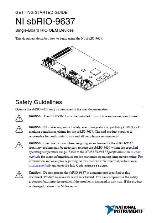
GETTING STARTED GUIDENI sbRIO-9637Single-Board RIO OEM DevicesThis document describes how to begin using the NI sbRIO-9637.Safety GuidelinesOperate the sbRIO-9637 only as described in the user documentation.Caution The sbRIO-9637 must be installed in a suitable enclosure prior to use.Caution NI makes no product safety, electromagnetic compatibility (EMC), or CEmarking compliance claims for the sbRIO-9637. The end-product supplier isresponsible for conformity to any and all compliance requirements.Caution Exercise caution when designing an enclosure for the sbRIO-9637.Auxiliary cooling may be necessary to keep the sbRIO-9637 within the specifiedoperating temperature range. Refer to the NI sbRIO-9637 Specifications on /manuals for more information about the maximum operating temperature rating. Forinformation and examples regarding factors that can affect thermal performance,visit /info and enter the Info Code sbriocooling.Caution Do not operate the sbRIO-9637 in a manner not specified in thisdocument. Product misuse can result in a hazard. You can compromise the safetyprotection built into the product if the product is damaged in any way. If the productis damaged, return it to NI for repair.Safety VoltagesConnect only voltages that are below these limits.V terminal to C terminal30 VDC maximum, Measurement Category I Measurement Category I is for measurements performed on circuits not directly connected to the electrical distribution system referred to as MAINS voltage. MAINS is a hazardous live electrical supply system that powers equipment. This category is for measurements of voltages from specially protected secondary circuits. Such voltage measurements include signal levels, special equipment, limited-energy parts of equipment, circuits powered by regulated low-voltage sources, and electronics.Caution Do not connect the sbRIO-9637 to signals or use for measurements withinMeasurement Categories II, III, or IV.Preparing the EnvironmentEnsure that the environment in which you are using the sbRIO-9637 meets the following specifications.-40 °C to 85 °CLocal ambient operating temperature neardevice (IEC 60068-2-1, IEC 60068-2-2)Maximum reported onboard sensor temperatureCPU/FPGA temperature98 °CPrimary System temperature85 °CSecondary System temperature85 °CNote Ensure that the local ambient, reported CPU/FPGA, and reported PrimarySystem temperatures do not exceed any of the maximum temperatures listed in thisdocument. For more information about how to access the onboard sensors, visit/info and enter the Info Code sbriosensors.Operating humidity (IEC 60068-2-78)10% RH to 90% RH, noncondensing Pollution Degree (IEC 60664)2Maximum altitude5,000 mIndoor use only.Note Refer to the device specifications on /manuals for completespecifications.2| | NI sbRIO-9637 Getting Started GuideUnpacking the KitCaution To prevent electrostatic discharge (ESD) from damaging the device,ground yourself using a grounding strap or by holding a grounded object, such as your computer chassis.1.Touch the antistatic package to a metal part of the computer chassis.2.Remove the device from the package and inspect the device for loose components or anyother sign of damage.CautionNever touch the exposed pins of connectors.Note Do not install a device if it appears damaged in any way.3.Unpack any other items and documentation from the kit.Store the device in the antistatic package when the device is not in use.Verifying the Kit ContentsVerify that the following items are included in the sbRIO-9637 kit.Figure 1.sbRIO-9637 Kit Contents1.sbRIO Device2.NI CompactRIO Device Drivers Media3.Getting Started Guide4.Power Supply5.10-pin IDC to 9-pin DSUB Cable6.50-pin IDC Ribbon Cable7.Power Cable Assembly8.Standoffs and ScrewsNote The provided power supply is only intended for the getting startedexperience. NI recommends the use of a power supply that meets the specifications listed in the NI sbRIO-9637 Specifications for system deployment.NI sbRIO-9637 Getting Started Guide | © National Instruments | 3Installing Software on the Host ComputerBefore using the sbRIO-9637, you must install the following application software and device drivers on the host computer.bVIEW 2015 or laterbVIEW Real-Time Module 2015 or laterbVIEW FPGA Module 2015 or later4.NI CompactRIO Device Drivers August 2015 or laterFor minimum software support information, visit /info and enter the Info Code softwareversion.Connecting the sbRIO-9637The sbRIO-9637 has the following components.Figure 2. sbRIO-9637 Components1.W3, RS-485 (COM3)2.W4, RS-232 (COM2)3.J6, SDHC4.J9, Power Connector5.Chassis Ground Bracket6.J10, USB Host Port7.W1, CAN (CAN0)8.J7, RJ-45 Ethernet Port9.W2, RS-232 (COM1)10.Reset Switch 11.LEDs12.J4, DIO13.J5, MIO14.Mounting Holes Connected to Chassis Ground15.Ethernet RGMII Transceiver16.ULPI USB T ransceiver17.FPGA Processor18.DDR Memory19.NAND Flash20.CPLD4| | NI sbRIO-9637 Getting Started GuideConnecting the sbRIO-9637 to PowerThe NI sbRIO device requires a 9 VDC to 30 VDC external power supply. The NI sbRIO device filters and regulates the supplied power and provides power for RMCs.Note Refer to the Power Requirements section of the NI sbRIO-9637Specifications for the complete power requirement specifications.Note Refer to the Power Requirements section of the NI sbRIO-9637 User Manualfor formulas and examples for calculating power requirements for differentconfigurations and application types.Note Refer to the Power Requirements section of the NI sbRIO-9637 User Manualfor proper wiring of the power cable assembly.Complete the following steps to connect a power supply to the device.Caution Do not mate or unmate the power supply connectors while power isapplied.1.Ensure that your power supply is powered off.2.Insert the power connector plug into the power connector receptacle of the NI sbRIOdevice until the connector latches into place.3.Turn on the power supply.Powering On the NI sbRIO DeviceThe NI sbRIO device runs a power-on self test (POST) when you apply power to the device. During the POST, the Power and Status LEDs turn on. When the Status LED turns off, the POST is complete. If the LEDs do not behave in this way when the system powers on, refer to the STATUS LED Indicators section.Connecting the sbRIO-9637 to the Host Computer Complete the following steps to connect the sbRIO-9637 to the host computer using the RJ-45 Ethernet port.1.Power on the host computer.2.Connect the sbRIO-9637 to the host computer using a standard Category 5 (CAT-5) orbetter shielded, twisted-pair Ethernet cable.Caution To prevent data loss and to maintain the integrity of your Ethernetinstallation, do not use a cable longer than 100 m.The first time you power up the device, it attempts to initiate a DHCP networkconnection. If the device is unable to initiate a DHCP connection, it connects to thenetwork with a link-local IP address with the form 169.254.x.x. After the device hasNI sbRIO-9637 Getting Started Guide| © National Instruments| 5powered up, you must install software on the device and configure the network settings in MAX.Note Installing software may change the network behavior of the device. Forinformation about network behavior by installed software version, visit /info and enter the Info Code ipconfigcrio.Configuring the System in Measurement & Automation Explorer (MAX)Complete the following steps to find the system in MAX.unch MAX on the host computer.2.Expand Remote Systems in the configuration tree and locate your system.3.Tip MAX lists the system under the model number followed by the serialnumber, such as NI-sbRIO-9637-########.Complete the following steps to set a system password.Note The default username for the sbRIO-9637 is admin. There is no defaultpassword for the sbRIO-9637, so you must leave the password field blank whenlogging in until you set a system password.1.Right-click your system and select Web Configuration.The NI Web-Based Configuration and Monitoring utility opens in your default browser and is where you set the password. If you have not installed Microsoft Silverlight,NI Web-based Configuration & Monitoring prompts you to do so.2.Enter a unique name for your system in the Hostname field.3.Click the Security Configuration icon.4.Click Login.5.In the Login dialog box, enter the username admin and leave the password field blank.6.Click OK.7.Click Change Password.8.Enter and re-enter a new password.9.Click OK.10.Click Save.11.Click OK to confirm you are changing the password.Caution NI cannot recover lost system passwords. If you forget the password,you must contact NI and reformat the controller.6| | NI sbRIO-9637 Getting Started GuideInstalling Software on the sbRIO-9637Complete the following steps to install software on the sbRIO-9637.1.In MAX, expand your system under Remote Systems.2.Right-click Software.3.Add/Remove Software to launch the LabVIEW Real-Time Software Wizard.Tip You must log in if you set a system password.4.5.Click Next.6.Select NI Scan Engine from the software add-ons.Select any additional software to install. If you plan on using the sbRIO-9637 with theNext.Tip You can use this wizard at anytime to install additional software.7.Next.8.9.Click Next to start the installation.10.Click Finish when the installation is complete.Troubleshooting the sbRIO-9637The sbRIO-9637 is Not Communicating with the Network•Ensure that the Ethernet connections between the sbRIO-9637 and the host computer and the Ethernet connections between the host computer and the router are secure.•Ensure that you have the correct version of NI CompactRIO Device Drivers installed on the host computer. Visit /info and enter the Info Code softwareversion for theTip If you have recently upgraded LabVIEW, you must reinstall NICompactRIO Device Drivers.•e a standard Category 5 (CAT-5) or better shielded, twisted-pair Ethernet cable toconnect the sbRIO-9637 Ethernet port to a host computer. The sbRIO-9637 attempts to initiate a DHCP network connection at powerup.NI sbRIO-9637 Getting Started Guide| © National Instruments| 72.In MAX, expand your system under Remote Systems and select Troubleshoot RemoteSystem Discovery.System ResetThe following figure shows the reset behavior of the sbRIO-9637.Figure 3. Reset Button BehaviorPress and holdPress and holdRESET button for ≥ 5 sSTA TUS LED IndicatorsThe following table lists the STATUS LED indicators.8| | NI sbRIO-9637 Getting Started GuideTable 1. ST ATUS LED IndicatorsNI sbRIO-9637 Getting Started Guide| © National Instruments| 9Where to Go NextWorldwide Support and ServicesThe National Instruments website is your complete resource for technical support. At / support, you have access to everything from troubleshooting and application development self-help resources to email and phone assistance from NI Application Engineers.Visit /services for NI Factory Installation Services, repairs, extended warranty, and other services.Visit /register to register your National Instruments product. Product registration facilitates technical support and ensures that you receive important information updates from NI.National Instruments corporate headquarters is located at 11500 North Mopac Expressway, Austin, Texas, 78759-3504. National Instruments also has offices located around the world. For telephone support in the United States, create your service request at /support or 10| | NI sbRIO-9637 Getting Started Guidedial 1 866 ASK MYNI (275 6964). For telephone support outside the United States, visit the Worldwide Offices section of /niglobal to access the branch office websites, which provide up-to-date contact information, support phone numbers, email addresses, and current events.NI sbRIO-9637 Getting Started Guide| © National Instruments| 11Refer to the NI Trademarks and Logo Guidelines at /trademarks for information on National Instruments trademarks. Other product and company names mentioned herein are trademarks or trade names of their respective companies. For patents covering National Instruments products/technology, refer to the appropriate location: Help»Patents in your software, the patents.txt file on your media, or the National Instruments Patent Notice at /patents. Y ou can find information about end-user license agreements (EULAs) and third-party legal notices in the readme file for your NI product. Refer to the ExportCompliance Information at /legal/export-compliance for the National Instruments global trade compliance policy and how to obtain relevant HTS codes, ECCNs, and other import/export data. NI MAKES NO EXPRESS OR IMPLIED WARRANTIES AS TO THE ACCURACY OF THE INFORMATION CONT AINED HEREIN AND SHALL NOT BE LIABLE FOR ANY ERRORS. U.S. Government Customers: The data contained in this manual was developed at private expense and is subject to the applicable limited rights and restricted data rights as set forth in FAR 52.227-14, DFAR 252.227-7014, and DFAR 252.227-7015.© 2014—2015 National Instruments. All rights reserved.376416A-01Aug15。
- 1、下载文档前请自行甄别文档内容的完整性,平台不提供额外的编辑、内容补充、找答案等附加服务。
- 2、"仅部分预览"的文档,不可在线预览部分如存在完整性等问题,可反馈申请退款(可完整预览的文档不适用该条件!)。
- 3、如文档侵犯您的权益,请联系客服反馈,我们会尽快为您处理(人工客服工作时间:9:00-18:30)。
INTERFACE CIRCUITSApplication Note 763: Jul 12, 2001Guidelines for Proper Wiring of an RS-485 (TIA/EIA-485-A) NetworkThe proper method of wiring an RS-485 network is described, with recommendations for twistedpair cabling and correct location of termination resistors. Received waveforms are shown for examples of proper and improper cable termination. Network configurations are shown for simple single-transmitter/multiple receiver through multiple transceiver to multi-branched circuits. This application note is intended to provide basic guidelines for wiring an RS-485 network. The RS-485 specification (officially called TIA/EIA-485-A) does not specifically spell out how an RS-485 network should be wired. But it does give some guidelines. These guidelines and sound engineering practices are the basis of this note. The suggestions here, however, are by no means inclusive of all the different ways a network can be designed. RS-485 transmits digital information between multiple locations. Data rates can be up to, and sometimes greater than, 10Mbps. RS-485 is designed to transmit this information over significant lengths, and 1000 meters are well within its capability. The distance and the data rate with which RS-485 can be successfully used depend a great deal on the wiring of the system.WireRS-485 is designed to be a balanced system. Simply put, this means there are 2 wires, other than ground, that are used to transmit the signal.Figure 1. A balanced system uses 2 wires, other than ground, to transmit data. The system is called balanced, because the signal on one wire is ideally the exact opposite of the signal on the second wire. In other words, if one wire is transmitting a high, the other wire will be transmitting a low, and vice versa. See Figure 2./an763 Page 1 of 10Figure 2. The signals on the 2 wires of a balanced system are ideally opposite. Although RS-485 can be successfully transmitted using multiple types of media, it should be used with wiring commonly called "twisted pair."What Is Twisted Pair, and Why Is It Used?As its name implies, a twisted pair is simply a pair of wires that are of equal length and are twisted together. Using an RS-485-compliant transmitter with twisted-pair wire reduces two major sources of problems for designers of high-speed long-distance networks: radiated EMI and received EMI. Radiated EMI As shown in Figure 3, high-frequency components are present whenever fast edges are used in transmitting information. These fast edges are necessary at the higher data rates that RS-485 is capable of transmitting.Figure 3. Waveform of a 125kHz square wave and its FFT plot The resultant high-frequency components of these fast edges coupled with long wires can have the effect of radiating EMI. A balanced system used with twisted-pair wire reduces this effect by trying to make the system an inefficient radiator. It works on a very simple principle. As the signals on the wires are equal but opposite, the radiated signals from each wire will also tend to be equal but opposite. This has the effect of canceling each other out, meaning no net radiated EMI. However, this is based on the assumption that the wires are exactly the same length and in exactly the same location. Because it is impossible to have two wires in the same location at the same time, the wires should be as close to each other as possible. Twisting the wires helps counteract any remaining EMI due to the finite distance between the two wires./an763 Page 2 of 10Received EMI Received EMI is basically the same problem as radiated EMI but in reverse. The wiring used in an RS-485 system will also act as an antenna that receives unwanted signals. These unwanted signals could distort the desired signals, which, if bad enough, can cause data errors. For the same reason that twisted-pair wire helps prevent radiated EMI, it will also help reduce the effects of received EMI. Because the two wires are close together and twisted, the noise received on one wire will tend to be the same as that received on the second wire. This type of noise is referred to as "common-mode noise." As RS-485 receivers are designed to look for signals that are the opposite of each other, they can easily reject noise that is common to both.Characteristic Impedance of Twisted-Pair WireDepending on the geometry of the cable and the materials used in the insulation, twisted-pair wire will have a "characteristic impedance" associated with it that is usually specified by its manufacturer. The RS-485 specification recommends, but does not specifically dictate, that this characteristic impedance be 120 ohms. Recommending this impedance is necessary to calculate worst-case loading and common-mode voltage ranges given in the RS-485 specification. The specification probably does not dictate this impedance in the interest of flexibility. If for some reason 120-ohm cable cannot be used, it is recommended that the worstcase loading (the number of transmitters and receivers that can be used) and worst-case common-mode voltage ranges be recalculated to make sure the system under design will work. Publication TSB89 has a section specifically devoted to such calculations.Number of Twisted Pairs per TransmitterNow that we have a feel for the type of wire needed, the question arises as to how many twisted pairs a transmitter can drive. The short answer is exactly one. Although it is possible for a transmitter to drive more than one twisted pair under certain circumstances, this is not the intent of the specification.Termination ResistorsBecause of the high frequencies and the distances involved, proper attention must be paid to transmissionline effects. However, a thorough discussion of transmission-line effects and proper termination techniques are well beyond the scope of this application note. With this in mind, terminations will be briefly discussed in their simplest form as they relate to RS-485. A terminating resistor is simply a resistor that is placed at the extreme end or ends of a cable (Figure 4). The value of the terminating resistor is ideally the same value as the characteristic impedance of the cable.Figure 4. Termination resistors should be the same value of the characteristic impedance of the twisted pair and should be placed at the far ends of the cable. When the termination resistance isn't the same value as the characteristic impedance of the wiring, reflections will occur as the signal is traveling down the cable. This is governed by the equation (RtZo)/(Zo+Rt), where Zo is the impedance of the cable and Rt is the value of the terminating resistor. Although some reflections are inevitable due to cable and resistor tolerances, large enough mismatches can cause reflections big enough to bring about errors in the data. See Figure 5./an763 Page 3 of 10Figure 5. Using the circuit shown at the top, the waveform on the left was obtained with a MAX3485 driving a 120-ohm twisted pair terminated with 54 ohms. The waveform on the right was obtained with the cable terminated properly with 120 ohms. With this in mind, it is important to match the terminating resistance and the characteristic impedance as closely as possible. The position of the terminating resistors is also very important. Termination resistors should always be placed at the far ends of the cable. As a general rule, termination resistors should be placed at both far ends of the cable. Although properly terminating both ends is absolutely critical for most system designs, it can be argued that in one special case only one termination resistor is needed. This case occurs in a system when there is a single transmitter and that single transmitter is located at the far end of the cable. In this case it is unnecessary to place a termination resistor at the end of the cable with the transmitter, because the signal is intended to always travel away from this end of the cable.Maximum Number of Transmitters and Receivers on a NetworkThe simplest RS-485 network is comprised of a single transmitter and a single receiver. Although useful in a number of applications, RS-485 allows for greater flexibility by permitting multiple receivers and transmitters on a single twisted pair. The maximum allowed depends on how much each device loads down the system. In an ideal world, all receivers and inactive transmitters will have infinite impedance and will not load the system down in any way. In the real world, however, this isn't the case. Every receiver attached to the network and all inactive transmitters will add an incremental load. To help the designer of an RS-485 network figure out just how many devices can be added to a network, a hypothetical unit called a "unit load" was created. All devices that are connected to an RS-485 network should be characterized in regard to multiples or fractions of unit loads. Two examples are the MAX3485, which is specified at 1 unit load, and the MAX 487, which is specified at 1/4 of a unit load. The maximum number of unit loads allowed on a twisted pair, assuming a properly terminated cable with a characteristic impedance of 120 ohms or more, is 32. Using the examples given above, this means that up to 32 MAX3485s or up to 128 MAX487s can be placed on a single network./an763 Page 4 of 10Examples of Proper NetworksWith the above information, we are ready to design some RS-485 networks. Here are a few examples. One Transmitter, One Receiver The simplest network is one transmitter and one receiver (Figure 6). In this example, a termination resistor is shown at the transmitter end of the cable. Although unnecessary here, it is probably a good habit to design in both termination resistors. This allows the transmitter to be moved to locations other than the far end and permits additional transmitters to be added to the network should that become necessary.Figure 6. A one-transmitter one-receiver RS-485 network One Transmitter, Multiple Receivers Figure 7 shows a one-transmitter multiple-receivers network. Here, it is important to keep the distances from the twisted pair to the receivers as short as possible.Figure 7. A one-transmitter multiple-receivers RS-485 network Two Transceivers Figure 8 shows a two-transceivers network.Figure 8. A two-transceivers RS-485 network/an763 Page 5 of 10Multiple Transceivers Figure 9 shows a multiple-transceivers network. As in the one-transmitter and multiple-receivers example, it is important to keep the distances from the twisted pair to the receivers as short as possible.Figure 9. A multiple-transceivers RS-485 networkExamples of Improper NetworksThe diagrams below are examples of improperly configured systems. Each example shows the waveform obtained from the improperly designed network and compares it to a waveform from a properly designed system. The waveform is measured differentially at points A and B (A-B). Unterminated Network In this example, the ends of the twisted pair are unterminated. As the signal propagates down the wire, it encounters the open circuit at the end of the cable. This constitutes an impedance mismatch, bringing about reflections. In the case of an open circuit (as shown below), all of the energy is reflected back to the source, causing the waveform to become very distorted./an763 Page 6 of 10Figure 10. An unterminated RS-485 network (top) and its resultant waveform (left), compared with a waveform obtained from a correctly terminated network (right) Wrong Termination Location Figure 11 shows a termination resistor, but it is located in a position other than the far end of the cable. As the signal propagates down the cable, it encounters two impedance mismatches. The first occurs at the termination resistor. Even though the resistor is matched to the characteristic impedance of the cable, there is still cable after the resistor. This extra cable causes a mismatch and therefore reflections. The second mismatch is at the end of the unterminated cable, leading to further reflections./an763 Page 7 of 10Figure 11. An RS-485 network with the termination resistor placed at the wrong location (top) and its resultant waveform (left), compared to a properly terminated network (right) Multiple Cables In Figure 12, there are multiple problems with the layout. The first problem is that RS-485 drivers are designed to drive only a single, properly terminated twisted pair. Here, the transmitters are each driving four twisted pairs in parallel. This means that the required minimum logic levels cannot be guaranteed. In addition to the heavy loading, there is an impedance mismatch at the point where multiple cables are connected. Impedance mismatches again mean reflections and therefore signal distortions./an763 Page 8 of 10Figure 12. An RS-485 network that uses multiple twisted pairs incorrectly Long Stubs In Figure 13, the cable is properly terminated and the transmitter is driving only a single twisted pair; however, the connection point (stub) for the receiver is excessively long. A long stub causes a significant impedance mismatch and thus reflections. All stubs should be kept as short as possible./an763 Page 9 of 10Figure 13. An RS-485 network that has a 10-foot stub (top) and its resultant waveform (left), compared to a waveform obtained with a short stubReferences1. TIA/EIA-485-A Electrical Characteristics of Generators and Receivers for Use in Balanced Digital Multipoint Systems 2. TSB89 Application Guidelines for TIA/EIA-485-A January 2001MORE INFORMATION MAX1480E: QuickView MAX1490E: QuickView MAX3157: QuickView-- Full (PDF) Data Sheet (1.7M) -- Full (PDF) Data Sheet (1.7M) -- Full (PDF) Data Sheet (320k)-- Free Sample -- Free Sample -- Free Sample/an763 Page 10 of 10。