HY62LF16206A-LT12C中文资料
XC62HP6001DL资料

505XC62H ETR0312_001.doc◆CMOS Low Power Consumption◆Small Dropout : 0.18V @ 60mA0.58V @ 160mA ◆Maximum Output Current : 165mA (V OUT =3.0V)◆Highly Accurate : ±2% (±1%) ◆Output Voltage Range: 2.0V~6.0V◆Stand-by Supply Current : 0.1μA (V OUT=3.0V) ◆SOT-25/SOT-89-5/USP-6B Package■GENERAL DESCRIPTIONThe XC62H series are highly precise, low power consumption,positive voltage regulators, manufactured using CMOS and laser trimming technologies. The series consists of a high precision voltage reference, an error correction circuit, and anoutput driver with current limitation.By way of the CE function, with output turned off, the series enters standby. In the stand-by mode, power consumption is greatly reduced. SOT-25 (150mW), SOT-89-5 (500mW) and USP-6B (100mW)packages are available.In relation to the CE function, as well as the positive logic XC62HR series, a negative logic XC62HP series (custom) is also available. ■APPLICATIONS●Battery powered equipment ●Voltage supplies for cellular phones ●Cameras, Video recorders ●Palmtops■TYPICAL APPLICATION CIRCUIT■FEATURESMaximum Output Current: 165mA (within max. p ower dissipation, V OUT =3.0V)Output Voltage Range : 2.0V ~ 6.0V in 100mV increments (1.5V ~ 1.9V semi-custom) Highly Accurate : Set-up Voltage ±2% (±1% for semi-custom products)Low Power Consumption: 3.0μA (TYP.) (V OUT =3.0, Output enabled): 0.1μA (TYP .) (Output disabled) Output Voltage Temperature Characteristics : ±100ppm /℃ (TYP .) Line Regulation : 0.2% / V (TYP .)Ultra Small Packages : SOT-25 (150mW) mini-moldSOT-89-5 (500mW) mini-power moldUSP-6B (100mW)■TYPICAL PERFORMANCE CHARACTERISTICS506XC62H SeriesSERIES CEVOLTAGE OUTPUTH ONXC62HR L OFFH OFFXC62HPL ONDESIGNATORDESCRIPTION SYMBOL DESCRIPTIONR : Positive ① CE Pin Logic P : Negative (Custom)② ③ Output Voltage 20~60:e.g. V OUT 3.0V → ②=3, ③=0V OUT 5.0V → ②=5, ③=0④ Temperature Characteristics 0 : + 100ppm (TYP .) 1 : + 1% (semi-custom) ⑤Output Voltage Accuracy2 : + 2% M : SOT-23 P : SOT-89-5 ⑥ Package TypeD :USP-6B R : Embossed tape, standard feed ⑦Device OrientationL : Embossed tape, reverse feedPIN NUMBERSOT-25 SOT-89-5 USP-6B PIN NAME FUNCTION 142, 5(NC)No Connection2 2 1 VIN Supply Voltage Input3 3 6 CE Chip Enable4 1 4 VSSGround5 5 3 VOUT Regulated Output Voltage■PIN CONFIGURATION*The dissipation pad for the USP-6B package should be solder-plated in recommended mount pattern and metal masking so as to enhance mounting strength and heat release.If the pad needs to be connected to other pins, it should be connected to the V IN pin.■PIN ASSIGNMENT■PRODUCT CLASSIFICATION●Ordering InformationXC62H ①②③④⑤⑥⑦■FUNCTIONH = High level L = Low level507XC62HSeries■PACKAGING INFORMATION●SOT-89-5●SOT-25 ●USP-6B508XC62H SeriesMARK VOLTAGE (V)MARK VOLTAGE (V)0 0.x -0 0.x1 1.x -1 1.x2 2.x -2 2.x3 3.x -3 3.x4 4.x -4 4.x5 5.x -5 5.x6 6.x -6 6.x7 7.x -7 7.x8 8.x -8 8.x9 9.x -9 9.x MARKVOLTAGE (V)MARK VOLTAGE (V)0 x.0 -x.01 x.1 -1 x.12 x.2 -2 x.23 x.3 -3 x.34 x.4 -4 x.45 x.5 -5 x.56 x.6 -6 x.67 x.7 -7 x.78 x.8 -8 x.89 x.9 -9 x.9■ MARKING RULE●SOT-25, SOT-89-5①②③④12354SOT-25(TOP VIEW)① Represents integer of the output voltage② Represents decimal number of the output voltage③ Based on internal standards ④ Represents assembly lot number.0 to 9, A to Z repeated (G, I, J, O, Q, W excepted)■BLOCK DIAGRAM524④③②①123SOT-89-5(TOP VIEW)509XC62HSeriesPARAMETER SYMBOLRATINGSUNITSInput Voltage V IN 12.0 V Output Current I OUT 500 mA Output Voltage V OUT V SS -0.3 ~ V IN +1.3 V CE Input VoltageV CEV SS -0.3 ~ V IN +1.3VSOT-25 150 SOT-89-5 500 Power DissipationUSP-6BPd 100mW Operating Temperature Range Topr-30 ~ +80 ℃ Storage Temperature RangeTstg-40 ~ +25℃===■ABSOLUTE MAXIMUM RATINGSTa=25℃■ELECTRICAL CHARACTERISTICSNOTE:*1: V OUT(T)=Specified output voltage .*2: V OUT(E)=Effective output voltage (i.e. the output voltage when "V OUT(T)+1.0V" is provided at the V IN pin while maintaining a certain I OUT value). *3: Vdif= {V IN1 (*5)-V OUT1 (*4)}*4: V OUT1= A voltage equal to 98% of the output voltage whenever an amply stabilized I OUT {V OUT(T)+1.0V} is input. *5: V IN1= The input voltage when V OUT1 appears as input voltage is gradually decreased.OUT(T)=(*1)XC62H Series■ELECTRICAL CHARACTERISTICS(Continued)OUT(T)=(*1)XC62HR4002 V OUT(T)=4.0V (*1)NOTE:*1: V OUT(T)=Specified output voltage .*2: V OUT(E)=Effective output voltage (i.e. the output voltage when "V OUT(T)+1.0V" is provided at the V IN pin while maintaining a certain I OUT value).*3: Vdif= {V IN1(*5)-V OUT1(*4)}*4: V OUT1= A voltage equal to 98% of the output voltage whenever an amply stabilized I OUT {V OUT(T)+1.0V} is input.*5: V IN1= The input voltage when V OUT1 appears as input voltage is gradually decreased.510511XC62HSeries===■ELECTRICAL CHARACTERISTICS (Continued)NOTE:*1: V OUT(T)=Specified output voltage . *2: V OUT(E)=Effective output voltage (i.e. the output voltage when "VOUT(T)+1.0V" is provided at the V IN pin while maintaining a certain I OUT value). *3: Vdif= {V IN1(*5)-V OUT1(*4)}*4: V OUT1= A voltage equal to 98% of the output voltage whenever an amply stabilized I OUT {V OUT(T)+1.0V} is input. *5: V IN1= The input voltage when V OUT1 appears as input voltage is gradually decreased.Ta=25℃XC62HR5002 V OUT(T)=5.0V (*1)512XC62H Series■TYPICAL APPLICATION CIRCUIT●Standard CircuitCircuit 1Circuit 2■TEST CIRCUITS513XC62HSeries■TYPICAL PERFORMANCE CHARACTERISTICS(1) Output Voltage vs. Output Current(2) Output Voltage vs. Input Voltage514XC62H Series■TYPICAL PERFORMANCE CHARACTERISTICS (Continued)(2) Output Voltage vs. Input Voltage (Continued)(3) Dropout Voltage vs. Output Current515■TYPICAL PERFORMANCE CHARACTERISTICS (Continued)(4) CE Pin Threshold Voltage vs. Input Voltage(5) Supply Current vs. Input Voltage516■TYPICAL PERFORMANCE CHARACTERISTICS (Continued)(5) Supply Current vs. Input Voltage (Continued) (6) Output Voltage vs. Ambient Temperature517■TYPICAL PERFORMANCE CHARACTERISTICS (Continued) (7) Supply Current vs. Ambient Temperature(8) Input Transient Response 1518■TYPICAL PERFORMANCE CHARACTERISTICS (Continued) (8) Input Transient Response 1 (Continued)(9) Input Transient Response 2519■TYPICAL PERFORMANCE CHARACTERISTICS (Continued) (9) Input Transient Response 2 (Continued)(10) Load Transient Response520■TYPICAL PERFORMANCE CHARACTERISTICS (Continued) (10) Load Transient Response (Continued)(11) CE Pin Transient Response521■TYPICAL PERFORMANCE CHARACTERISTICS (Continued) (11) CE Pin Transient Response (Continued)(12) Ripple Rejection Rate。
LT6220资料
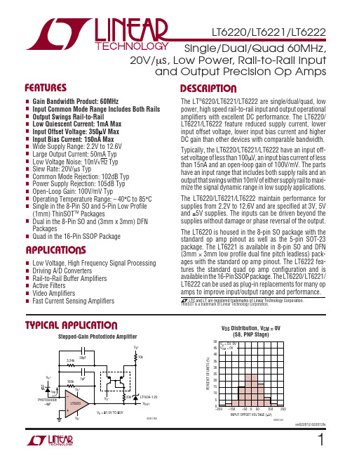
12ELECTRICAL CHARACTERISTICST A = 25°C, V S = 5V, 0V; V S = 3V, 0V; V CM = V OUT = half supply, unless otherwise notedSYMBOL PARAMETER CONDITIONS MIN TYP MAX UNITS V OS Input Offset Voltage V CM = 0V70350µVV CM = 0V (DD Package)150700µVV CM = 0V (S5 Package)200850µVV CM = V S0.5 2.5mVV CM = V S (S5 Package)0.53mV ∆V OS Input Offset Voltage Shift V S = 5V, V CM = 0V to 3.5V30195µVV S = 3V, V CM = 0V to 1.5V15120µV Input Offset Voltage Match (Channel-to-Channel)V CM = 0V100600µV (Note 9)V CM = 0V (DD Package)1501100µV I B Input Bias Current V CM = 1V15150nAV CM = V S250600nA Input Bias Current Match (Channel-to-Channel)V CM = 1V15175nA (Note 9)V CM = V S20250nA I OS Input Offset Current V CM = 1V15100nAV CM = V S15100nA Input Noise Voltage0.1Hz to 10Hz0.5µV P-P e n Input Noise Voltage Density f = 10kHz10nV/√Hz i n Input Noise Current Density f = 10kHz0.8pA/√Hz C IN Input Capacitance2pF A VOL Large Signal Voltage Gain V S = 5V, V O = 0.5V to 4.5V, R L = 1k at V S/235100V/mVV S = 5V, V O = 1V to 4V, R L = 100Ω at V S/2 3.510V/mVV S = 3V, V O = 0.5V to 2.5V, R L = 1k at V S/23090V/mV CMRR Common Mode Rejection Ratio V S = 5V, V CM = 0V to 3.5V85102dBV S = 3V, V CM = 0V to 1.5V82102dB CMRR Match (Channel-to-Channel) (Note 9)V S = 5V, V CM = 0V to 3.5V79100dBV S = 3V, V CM = 0V to 1.5V76100dB Input Common Mode Range0V S V PSRR Power Supply Rejection Ratio V S = 2.5V to 10V, V CM = 0V84105dB PSRR Match (Channel-to-Channel) (Note 9)79105dB Minimum Supply Voltage (Note 6) 2.2 2.5V V OL Output Voltage Swing LOW (Note 7)No Load540mVI SINK = 5mA100200mVI SINK = 20mA325650mV V OH Output Voltage Swing HIGH (Note 7)No Load540mVI SOURCE = 5mA130250mVI SOURCE = 20mA475900mV I SC Short-Circuit Current V S = 5V2045mAV S = 3V2035mA I S Supply Current Per Amplifier0.91mA GBW Gain-Bandwidth Product V S = 5V, Frequency = 1MHz3560MHz SR Slew Rate V S = 5V, A V = –1, R L= 1k, V O = 4V1020V/µs FPBW Full Power Bandwidth V S = 5V, A V = 1, V O = 4V p-p 1.6MHz HD Harmonic Distortion V S = 5V, A V = 1, R L= 1k, V O = 2V P-P, f C = 500kHz–77.5dBc t S Settling Time0.01%, V S = 5V, V STEP = 2V, A V = 1, R L= 1k 300ns ∆G Differential Gain (NTSC)V S = 5V, A V = 2, R L= 1k0.3%∆θDifferential Phase (NTSC)V S = 5V, A V = 2, R L= 1k0.3Degsn622012 622012fs34sn622012 622012fsSYMBOL PARAMETER CONDITIONS MIN TYP MAX UNITS V OSInput Offset VoltageV CM = 0V●90500µV V CM = 0V (DD Package)●180850µV V CM = 0V (S5 Package)●2301250µV V CM = V S●0.53mV V CM = V S (S5 Package)●0.5 3.5mV ∆V OSInput Offset Voltage ShiftV S = 5V, V CM = 0V to 3.5V ●30280µV V S = 3V, V CM = 0V to 1.5V●15190µV Input Offset Voltage Match (Channel-to-Channel)V CM = 0V ●110850µV (Note 9)V CM = 0V (DD Package)●1801400µV V OS TC Input Offset Voltage Drift (Note 8)● 1.55µV/°C (S5 Package)● 3.510µV/°C I BInput Bias CurrentV CM = 1V●20175nA V CM = V S – 0.2V ●275800nA Input Bias Current Match (Channel-to-Channel)V CM = 1V●15200nA (Note 9)V CM = V S – 0.2V ●20300nA I OS Input Offset Current V CM = 1V●15125nA V CM = V S – 0.2V●15125nA A VOLLarge Signal Voltage GainV S = 5V, V O = 0.5V to 4.5V, R L = 1k at V S /2●3090V/mV V S = 5V, V O = 1V to 4V, R L = 100Ω at V S /2●39V/mV V S = 3V, V O = 0.5V to 2.5V, R L = 1k at V S /2●2580V/mV CMRR Common Mode Rejection RatioV S = 5V, V CM = 0V to 3.5V ●82100dB V S = 3V, V CM = 0V to 1.5V ●78100dB CMRR Match (Channel-to-Channel) (Note 9)V S = 5V, V CM = 0V to 3.5V ●77100dB V S = 3V, V CM = 0V to 1.5V ●73100dBInput Common Mode Range●0V SV PSRR Power Supply Rejection RatioV S = 2.5V to 10V, V CM = 0V●81104dB PSRR Match (Channel-to-Channel) (Note 9)●76104dB Minimum Supply Voltage (Note 6)●2.2 2.5V V OLOutput Voltage Swing LOW (Note 7)No Load ●850mV I SINK = 5mA ●110220mV I SINK = 20mA ●375750mV V OHOutput Voltage Swing HIGH (Note 7)No Load●850mV I SOURCE = 5mA ●150300mV I SOURCE = 20mA ●6001100mV I SC Short-Circuit Current V S = 5V ●2040mA V S = 3V●2030mAI S Supply Current Per Amplifier ●1 1.4mA GBW Gain-Bandwidth Product V S = 5V, Frequency = 1MHz ●3060MHz SRSlew RateV S = 5V, A V = –1, R L = 1k, V O = 4V P-P●918V/µsELECTRICAL CHARACTERISTICSThe ● denotes the specifications which apply over the 0°C ≤ T A ≤ 70°Ctemperature range. V S = 5V, 0V; V S = 3V, 0V; V CM = V OUT = half supply, unless otherwise noted.5sn622012 622012fsSYMBOL PARAMETER CONDITIONS MIN TYP MAX UNITS V OSInput Offset VoltageV CM = 0V●125700µV V CM = 0V (DD Package)●3001300µV V CM = 0V (S5 Package)●3502000µV V CM = V S●0.75 3.5mV V CM = V S (S5 Package)●1 4.5mV ∆V OSInput Offset Voltage ShiftV S = 5V, V CM = 0V to 3.5V ●30300µV V S = 3V, V CM = 0V to 1.5V●30210µV Input Offset Voltage Match (Channel-to-Channel)V CM = 0V ●1751200µV (Note 9)V CM = 0V (DD Package)●3002200µV V OS TC Input Offset Voltage Drift (Note 8)● 1.57.5µV/°C (S5 Package)● 3.515µV/°C I BInput Bias CurrentV CM = 1V●25200nA V CM = V S – 0.2V ●300900nA Input Bias Current Match (Channel-to-Channel)V CM = 1V●15250nA (Note 9)V CM = V S – 0.2V ●20350nA I OS Input Offset Current V CM = 1V●20150nA V CM = V S – 0.2V●20150nA A VOLLarge Signal Voltage GainV S = 5V, V O = 0.5V to 4.5V, R L = 1k at V S /2●2570V/mV V S = 5V, V O = 1.5V to 3.5V, R L = 100Ω at V S /2● 2.58V/mV V S = 3V, V O = 0.5V to 2.5V, R L = 1k at V S /2●2060V/mV CMRR Common Mode Rejection RatioV S = 5V, V CM = 0V to 3.5V ●81100dB V S = 3V, V CM = 0V to 1.5V ●77100dB CMRR Match (Channel-to-Channel) (Note 9)V S = 5V, V CM = 0V to 3.5V ●76100dB V S = 3V, V CM = 0V to 1.5V ●72100dBInput Common Mode Range●0V SV PSRR Power Supply Rejection RatioV S = 2.5V to 10V, V CM = 0V●79104dB PSRR Match (Channel-to-Channel) (Note 9)●74104dB Minimum Supply Voltage (Note 6)●2.2 2.5V V OLOutput Voltage Swing LOW (Note 7)No Load ●1060mV I SINK = 5mA ●120240mV I SINK = 10mA ●220450mV V OHOutput Voltage Swing HIGH (Note 7)No Load●1060mV I SOURCE = 5mA ●160325mV I SOURCE = 10mA ●325650mV I SC Short-Circuit Current V S = 5V ●12.530mA V S = 3V●12.525mAI S Supply Current Per Amplifier ● 1.1 1.5mA GBW Gain-Bandwidth Product V S = 5V, Frequency = 1MHz ●2550MHz SRSlew RateV S = 5V, A V = –1, R L = 1k, V O = 4V●815V/µsELECTRICAL CHARACTERISTICSThe ● denotes the specifications which apply over the –40°C ≤ T A ≤ 85°Ctemperature range. V S = 5V, 0V; V S = 3V, 0V; V CM = V OUT = half supply unless otherwise noted. (Note 5)ELECTRICAL CHARACTERISTICST A = 25°C, V S = ±5V, V CM = 0V, V OUT = 0V, unless otherwise noted.SYMBOL PARAMETER CONDITIONS MIN TYP MAX UNITS V OS Input Offset Voltage V CM = –5V80500µVV CM = –5V (DD Package)150750µVV CM = –5V (S5 Package)200900µVV CM = 5V0.7 2.5mVV CM = 5V (S5 Package)0.73mV ∆V OS Input Offset Voltage Shift V CM = –5V to 3.5V70675µV Input Offset Voltage Match (Channel-to-Channel)V CM = –5V100850µVV CM = –5V (DD Package)1501300µV I B Input Bias Current V CM = –4V20150nAV CM = 5V250700nA Input Bias Current Match (Channel-to-Channel)V CM = –4V15175nAV CM = 5V20250nA I OS Input Offset Current V CM = –4V15100nAV CM = 5V15100nA Input Noise Voltage0.1Hz to 10Hz0.5µV P-P e n Input Noise Voltage Density f = 10kHz10nV/√Hz i n Input Noise Current Density f = 10kHz0.8pA/√Hz C IN Input Capacitance f = 100kHz2pF A VOL Large Signal Voltage Gain V O = –4V to 4V, R L = 1k3595V/mVV O = –2V to 2V, R L = 100Ω 3.510V/mV CMRR Common Mode Rejection Ratio V CM = –5V to 3.5V82102dB CMRR Match (Channel-to-Channel)77100dB Input Common Mode Range V S–V S+V PSRR Power Supply Rejection Ratio V S+ = 2.5V to 10V, V S–= 0V, V CM = 0V84105dB PSRR Match (Channel-to-Channel)79105dB V OL Output Voltage Swing LOW (Note 7)No Load540mVI SINK = 5mA100200mVI SINK = 20mA325650mV V OH Output Voltage Swing HIGH (Note 7)No Load540mVI SOURCE = 5mA130250mVI SOURCE = 20mA475900mV I SC Short-Circuit Current2550mA I S Supply Current Per Amplifier1 1.5mA GBW Gain-Bandwidth Product Frequency = 1MHz60MHz SR Slew Rate A V = –1, R L = 1k, V O = ±4V,20V/µsMeasure at V O = ±2VFPBW Full Power Bandwidth V O = 8V P-P0.8MHz HD Harmonic Distortion A V = 1, R L= 1k, V O = 2V p-p, f c = 500kHz–77.5dBc t S Settling Time0.01%, V STEP = 5V, A V = 1, R L = 1k375ns ∆G Differential Gain (NTSC)A V = 2, R L = 1k0.15%∆θDifferential Phase (NTSC)A V = 2, R L = 1k0.6Deg6sn622012 622012fs7sn622012 622012fsSYMBOL PARAMETER CONDITIONSMIN TYP MAX UNITS V OSInput Offset VoltageV CM = –5V●100650µV V CM = –5V (DD Package)●180900µV V CM = –5V (S5 Package)●2301300µV V CM = 5V●0.753mV V CM = 5V (S5 Package)●0.75 3.5mV ∆V OSInput Offset Voltage ShiftV CM = –5V to 3.5V●90850µV Input Offset Voltage Match (Channel-to-Channel)V CM = –5V ●901100µV (Note 9)V CM = –5V (DD Package)●1801500µV V OS TC Input Offset Voltage Drift (Note 8)● 1.55µV/°C (S5 Package)● 3.510µV/°C I BInput Bias CurrentV CM = –4V ●20175nA V CM = 4.8V ●275800nA Input Bias Current Match (Channel-to-Channel)V CM = –4V ●15200nA (Note 9)V CM = 4.8V ●20300nA I OS Input Offset Current V CM = –4V ●15125nA V CM = 4.8V●15125nA A VOL Large Signal Voltage Gain V O = –4V to 4V, R L = 1k ●3090V/mV V O = –2V to 2V, R L =100Ω●39V/mV CMRRCommon Mode Rejection RatioV CM = –5V to 3.5V●80100dB CMRR Match (Channel-to-Channel) (Note 9)●75100dBInput Common Mode Range●V S –V S +V PSRR Power Supply Rejection RatioV S + = 2.5V to 10V, V S –= 0V, V CM = 0V●81104dB PSRR Match (Channel-to-Channel) (Note 9)●76104dB V OLOutput Voltage Swing LOW (Note 7)No Load ●850mV I SINK = 5mA ●110220mV I SINK = 20mA ●375750mV V OHOutput Voltage Swing HIGH (Note 7)No Load●850mV I SOURCE = 5mA ●150300mV I SOURCE = 20mA ●6001100mV I SC Short-Circuit Current ●2040mA I S Supply Current Per Amplifier ●1.22mA GBW Gain-Bandwidth Product Frequency = 1MHz ●60MHz SRSlew RateA V = –1, R L = 1k , V O = ±4V,●18V/µsMeasure at V O = ±2VELECTRICAL CHARACTERISTICSThe ● denotes the specifications which apply over the 0°C ≤ T A ≤ 70°Ctemperature range. V S = ±5V, V CM = 0V, V OUT = 0V, unless otherwise noted.SYMBOL PARAMETER CONDITIONS MIN TYP MAX UNITS V OS Input Offset Voltage V CM = –5V●150800µVV CM = –5V (DD Package)●3001300µVV CM = –5V (S5 Package)●3502000µVV CM = 5V●0.75 3.5mVV CM = 5V (S5 Package)●1 4.5mV ∆V OS Input Offset Voltage Shift V CM = – 5V to 3.5V●90950µV Input Offset Voltage Match (Channel-to-Channel)V CM = –5V●1751350µV (Note 9)V CM = –5V (DD Package)●3002200µV V OS TC Input Offset Voltage Drift (Note 8)● 1.57.5µV/°C(S5 Package)● 3.515µV/°C I B Input Bias Current V CM = –4V●25200nAV CM = 4.8V●300900nA Input Bias Current Match (Channel-to-Channel)V CM = –4V●15250nA (Note 9)V CM = 4.8V●20350nA I OS Input Offset Current V CM = –4V●20150nAV CM = 4.8V●20150nA A VOL Large Signal Voltage Gain V O = –4V to 4V, R L = 1k●2570V/mVV O = –1V to 1V, R L = 100Ω● 2.58V/mV CMRR Common Mode Rejection Ratio V CM = –5V to 3.5V●79100dB CMRR Match (Channel-to-Channel) (Note 9)●74100dB Input Common Mode Range●–5 5V PSRR Power Supply Rejection Ratio V S+= 2.5V to 10V, V S– = 0V, V CM = 0V●79104dB PSRR Match (Channel-to-Channel) (Note 9)●74104dB V OL Output Voltage Swing LOW (Note 7)No Load●1060mVI SINK = 5mA●120240mVI SINK = 10mA●220450mV V OH Output Voltage Swing HIGH (Note 7)No Load●1060mVI SOURCE = 5mA●160325mVI SOURCE = 10mA●325650mV I SC Short-Circuit Current●12.530mA I S Supply Current● 1.4 2.25mA GBW Gain-Bandwidth Product Frequency = 1MHz●50MHz SR Slew Rate A V = –1, R L = 1k,V O = ±4V,●15V/µsMeasure at V O = ±2VNote 1: Absolute Maximum Ratings are those values beyond which the life of a device may be impaired.Note 2: The inputs are protected by back-to-back diodes. If the differential input voltage exceeds 1.4V, the input current should be limited to less than 10mA.Note 3: A heat sink may be required to keep the junction temperature below the absolute maximum rating when the output is shorted indefinitely.Note 4: The LT6220C/LT6221C/LT6222C and LT6220I/LT6221I/LT6222I are guaranteed functional over the temperature range of –40°C and 85°C. Note 5: The LT6220C/LT6221C/LT6222C are guaranteed to meet specified performance from 0°C to 70°C. The LT6220C/LT6221C/LT6222C are designed, characterized and expected to meet specified performance from –40°C to 85°C but is not tested or QA sampled at these temperatures. The LT6220I/LT6221I/LT6222I are guaranteed to meet specified performance from –40°C to 85°C.Note 6: Minimum supply voltage is guaranteed by power supply rejection ratio test.Note 7: Output voltage swings are measured between the output and power supply rails.Note 8: This parameter is not 100% tested.Note 9: Matching parameters are the difference between amplifiers A and D and between B and C on the LT6222; between the two amplifiers on the LT6221.Note 10: Thermal resistance (θJA) varies with the amount of PC board metal connected to the package. The specified values are for short traces connected to the leads. If desired, the thermal resistance can be substantially reduced by connecting Pin 2 of the LT6220CS5/LT6220IS5 or the underside metal of DD packages to a larger metal area (V S– trace).ELECTRICAL CHARACTERISTICS The ● denotes the specifications which apply over the –40°C ≤ TA≤ 85°C temperature range. V S = ±5V, V CM = 0V, V OUT = 0V, unless otherwise noted. (Note 5)8sn622012 622012fs91011TIME (SECONDS)8622012 G202461071359V S = 5V, 0VV S = ±5V PHASEGain and Phase vs FrequencyV S = 5V, 0V100ns/DIV622012 G36A V = 1R L = 1k121314sn622012 622012fsA pair of complementary common emitter stages Q14/Q15that enable the output to swing from rail-to-rail construct the output stage. The capacitors C2 and C3 form the local feedback loops that lower the output impedance at high frequency. These devices are fabricated by Linear Technology’s proprietary high speed complementary bi-polar process.Power DissipationThe LT6222, with four amplifiers, is housed in a small 16-lead SSOP package and typically has a thermal resis-tance (θJA ) of 135°C/W. It is necessary to ensure that the die’s junction temperature does not exceed 150°C. The junction temperature, T J , is calculated from the ambient temperature, T A , power dissipation, P D , and thermal resis-tance, θJA :T J = T A + (P D • θJA )The power dissipation in the IC is the function of the supply voltage, output voltage and the load resistance. For a given supply voltage, the worst-case power dissipation P D(MAX)occurs when the maximum supply current and the output voltage is at half of either supply voltage for a given load resistance. P D(MAX) is given by:P V I V R D MAX S S MAX S L ()()•/=()+⎛⎝⎜⎞⎠⎟22Example: F or an LT6222 in a 16-lead SSOP package operating on ±5V supplies and driving a 100Ω load, the worst-case power dissipation is given by:P Amp mA mWD MAX ()/•../...=()+()=+=1018251000018006258052If all four amplifiers are loaded simultaneously, then the total power dissipation is 322mW.The maximum ambient temperature at which the part is allowed to operate is:T A = T J – (P D(MAX) • 135°C/W)= 150°C – (0.322W • 135°C/W) = 106.5°CAPPLICATIO S I FOR ATIOW UUU Input Offset VoltageThe offset voltage will change depending upon which input stage is active. The PNP input stage is active from the negative supply rail to 1.2V below the positive supply rail,then the NPN input stage is activated for the remaining input range up to the positive supply rail during which the PNP stage remains inactive. The offset voltage is typically less than 70µV in the range that the PNP input stage is active.Input Bias CurrentThe LT6220/LT6221/LT6222 employ a patent pending technique to trim the input bias current to less than 150nA for the input common mode voltage of 0.2V above the negative supply rail to 1.2V below the positive rail. The low input offset voltage and low input bias current of the LT6220/LT6221/LT6222 provide precision performance especially for high source impedance applications.OutputThe LT6220/LT6221/LT6222 can deliver a large output current, so the short-circuit current limit is set around 50mA to prevent damage to the device. Attention must be paid to keep the junction temperature of the IC below the absolute maximum rating of 150°C (refer to the Power Dissipation section) when the output is in continuous short circuit. The output of the amplifier has reverse-biased diodes connected to each supply. If the output is forced beyond either supply, unlimited current will flow through these diodes. If the current is transient and limited to several hundred milliamperes, no damage will occur to the device.Overdrive ProtectionWhen the input voltage exceeds the power supplies, two pair of crossing diodes, D1 to D4, will prevent the output from reversing polarity. If the input voltage exceeds either power supply by 700mV, diode D1/D2 or D3/D4 will turn on to keep the output at the proper polarity. For the phase reversal protection to perform properly, the input current must be limited to less than 5mA. If the amplifier is155µs/DIV622012 F03Figure 3. Stepped-Gain Photodiode Amplifier Response Single 3V Supply, 1MHz, 4th Order Butterworth Filter161718Information furnished by Linear Technology Corporation is believed to be accurate and reliable. However, no responsibility is assumed for its use. Linear Technology Corporation makes no represen-tation that the interconnection of its circuits as described herein will not infringe on existing patent rights.1920Linear Technology Corporation1630 McCarthy Blvd., Milpitas, CA 95035-7417(408) 432-1900 ● F AX: (408) 434-0507 ● © LINEAR TECHNOLOGY CORPORA TION 2003LT/TP 0204 1K • PRINTED IN USA。
L6201中文资料

10
11
D95IN216
PowerSO20
GND N.C. N.C. ENABLE SENSE Vref BOOT2 IN2 N.C. GND
MULTIWATT11 2/20
元器件交易网
L6201 - L6202 - L6203
PINS FUNCTIONS
L6201 1
Boostrap Peak Voltage
Total Power Dissipation: Tpins = 90°C for L6201
for L6202 Tcase = 90°C for L6201PS/L6203 Tamb = 70°C for L6201 (Note 2)
for L6202 (Note 2)
Not Connected
GND
Common Ground Terminal
6
GND
Common Ground Terminal
GND
Common Ground Terminal
N.C.
Not Connected
1
OUT2 Ouput of 2nd Half Bridge
2
Vs
Supply Voltage
ABSOLUTE MAXIMUM RATINGS
Symbol Vs VOD
VIN, VEN Io
Vsense Vb Ptot
Tstg, Tj
Parameter
Power Supply
Differential Output Voltage (between Out1 and Out2)
Input or Enable Voltage
元器件交易网
L6201
RM6206中文规格书-20130311

电流源,能使RM6206振荡的最小电流源
反馈防上限电流: 在常态下,当
电流;
VFB=6V,VIS=0.3V时,流入FB脚的电流;
启动电压: 上述条件下,能使RM6206振荡
内部反馈电源电压: 在常态下,当RM6206
的最大VCC电压;
无反馈电路时VCC脚的电压;
再启动电压:上述条件下,能使RM6206振
2013-03-11
3
电气特性
测试条件: T=25℃,,VCC=5.5-7.5V, Ct=680PF, RS=1Ω;
参数
符号
条件
输出
开关管最大耐压
IOC=10mA
饱和压降 输出上升时间 输出下降时间 输出限制电流
VS A T
Ioc=250mA
TR
CL=1nF
OC上限电流: VFB=6V,FB下拉电流开始动
荡的最小VCC电压;
作时OC流过的最小电流
振荡器关断电压: 上述条件下,能使振荡
器关断的VCC电压;
静态电流: FB脚外接1K欧姆电阻到地,流
2013-03-11
6
封装信息
RM6206
DIP-8
符号
炉等);
2013-03-11
1
典型应用:
RM6206
2013-03-11
2
管脚分布:
RM6206
管脚定义:
管脚 1 2 3 4 5 6
7、8
符号 OB VCC GND FB IS NC OC
功能描述 功率管基极,启动电流输入脚,外接启动电阻到高压直流端
电源输入脚 接地脚
电压反馈脚 电流侦测脚
航嘉电源2013年产品手册
C:\Documents and
外观结构图:Settings\liyis\桌
C:\Documents and
线材接口图(仅供参考,以实物为准):Settings\liyis\桌
航嘉行业电源产品手册 项目处:李义霜 18926759036
●型号:HK250-93FP
●规格明细
输入参数 90V-265VAC(47Hz-63Hz) 3A Max
≤3W
过压保护、过流保护、欠压保护、短路保护、过功率保护
空气温度:0摄氏度~40摄氏度,相对湿度:5%~85% 无凝露
空气温度:-40摄氏度~70摄氏度,相对湿度:5%~95%
符合 GB9254 Class B
≤3.5mA(264VAC/60HZ)
≥100K 小时.MIL-HDBK-217F(25℃)
冷却方式
采用强制冷却、双滚珠风扇散热
包装方式
20PCS 每箱
典型尺寸(mm) 150(L)×80(W)×40(H)
设计规范
符合 Intel Flex 12V 1.0 规范
应用领域
路由器、防火墙、广告机等
纹波及噪声
≤50mV ≤120mV ≤50mV ≤50mV ≤120mV
C:\Documents and
≤3W
过压保护、过流保护、欠压保护、短路保护、过功率保护
空气温度:0摄氏度~50摄氏度,相对湿度:5%~95% 无凝露
空气温度:-40摄氏度~70摄氏度,相对湿度:5%~100%
符合 GB9254 Class B
≤3.5mA(264VAC/60HZ)
≥100K 小时.MIL-HDBK-217F(25℃)
C:\Documents and
IN6206A系列

IN6206A 系列Ver 01IN6206A 系列低压差电压稳压器IN6206A 系列是高纹波抑制率、低功耗、低压差,具有过流和短路保护的 CMOS 降压型电压稳压器。
这些器件具有很低的静 态偏置电流(8.0μA Typ.) ,它们能在输入、 输出电压差极小的情况下提供 300mA 的输 出电流,并且仍能保持良好的调整率。
由于 输入输出间的电压差很小和静态偏置电流很 小,这些器件特别适用于希望延长有用电池 寿命的电池供电类产品,如计算机、消费类 产品和工业设备等。
特点• 高精度输出电压:±2%; • 输出电压:1.5V~5.0V(步长 0.1V); • 极低的静态偏置电流(Typ.=8.0μA); • 带载能力强:当 Vin=4.3V 且 Vout=3.3V 时 Iout=300mA; • 极低的输入输出电压差: 0.2V at 80mA and 0.40V at 160mA; • 输入稳定性好:Typ. 0.05%/V; • 低的温度调整系数; • 可以作为调整器和参考电压来使用; • 封装形式:SOT23, SOT89。
选型指南IN 62 06 A XX X用途• 电池供电系统; • 无绳电话设备; • 无线控制系统; • 便携/手掌式计算机; • 便携式消费类设备; • 便携式仪器; • 电子设备; • 汽车电子设备; • 电压基准源。
型号 IN6206Axx后缀 M P封装 SOT23-3 SOT89-3CE 端 No特点深圳市英康科技有限公司地址:深圳市·宝安龙华民治街道民治大道民泰大厦 520 电话:86-755-2818 7576 传真:0755-2818 8350Page 1 of 4IN6206A 系列Ver 01引脚排列图引脚分配IN6206Axx 引脚号 SOT23-3 1 2 3 SOT89-3 1 3 2 符号 Vss Vout Vin 引脚描述 接地引脚 电压输出端 电压输入端功能块框图极限参数参数 Vin 脚电压 Vout 脚电流 Vout 脚电压 SOT23 允许最大 SOT89 功耗 工作温度 存贮温度 焊接温度和时间 符号 VIN Iout Vout Pd Pd TOpr Tstg Tsolder 极限值 9.0 500 Vss-0.3 ~ Vout+0.3 300 500 -25 ~ +85 -40 ~ +125 260℃, 10s 单位 V mA V mW mW ℃ ℃深圳市英康科技有限公司地址:深圳市·宝安龙华民治街道民治大道民泰大厦 520 电话:86-755-2818 7576 传真:0755-2818 8350Page 2 of 4IN6206A 系列Ver 01主要参数及工作特性IN6206A30/33 O (Vin=Vout+1V,Cin=Cout=1u,Ta=25 C 除特别指定)特性 输出电压 输入电压 最大输出电流 负载特性 压差 (Note 3) 静态电流 电源电压调整 率 纹波抑制比 短路电流 过流保护电流 符号 VOUT(E) (Note 2) VIN IOUT (max) ∆VOUT Vdif1 Vdif2 ISS ∆VOUT ∆VIN * VOUT PSRR Ishort Ilimt 条件 IOUT=40mA, VIN=Vout+1V VIN=Vout+1V VIN=Vout+1V, 1mA≤IOUT≤100mA IOUT =80mA IOUT =200mA VIN=Vout+1V IOUT =40mA Vout+1V ≤VIN≤9V Vin= [Vout+1]V +1Vp-pAC IOUT =10mA,f=1kHz 最小值 X 0.98 300 30 200 400 8 0.05 50 10 500 典型值 VOUT(T) (Note 1) 最大值 X 1.02 8.0 mA mV mV mV μA %/V dB mA mA 单位 VIN6206A15 O (Vin=Vout+1V,Cin=Cout=1u,Ta=25 C 除特别指定)特性 输出电压 输入电压 最大输出电流 负载特性 压差 (Note 3) 静态电流 电源电压调整 率 纹波抑制比 短路电流 过流保护电流 符号 VOUT(E) (Note 2) VIN IOUT (max) ∆VOUT Vdif1 Vdif2 ISS ∆VOUT ∆VIN * VOUT PSRR Ishort Ilimt 条件 IOUT=5mA, VIN=Vout+1V VIN=Vout+1V VIN=Vout+1V, 1mA≤IOUT≤20mA IOUT =5mA IOUT =20mA VIN=Vout+1V IOUT =5mA Vout+1V ≤VIN≤5V Vin= [Vout+1]V +1Vp-pAC IOUT =5mA,f=1kHz 最小值 X 0.98 20 10 100 200 8 0.05 40 10 200 典型值 VOUT(T) (Note 1) 最大值 X 1.02 5.0 mA mV mV mV μA %/V dB mA mA 单位 V注 : 1. VOUT (T) :规定的输出电压 2. VOUT (E) :有效输出电压 ( 即当 IOUT 保持一定数值,VIN = (VOUT (T)+1.0V)时的输出电压。
LC1206A电源芯片资料

LC1206A电源芯片资料简述:LC1206A為高性能、電流模式PWM高壓開關控制器集成電路,專為家電控制器電源設計。
芯片具有獨特的交流電壓過零信號檢測與輸出控制電路,可輸出同步的交流電壓過零信號用於對繼電LC1206A為高性能、電流模式PWM高壓開關控制器集成電路,專為家電制器電源設計。
芯片具有獨特的交流電壓過零信號檢測與輸出控制電路,可輸出同步的交流電壓過零信號用於對繼電器、可控硅等進行過零切換控制,從而提高系統的可靠性,降低切換損耗,延長繼電器壽命。
高集成的設計則極大地簡化了電路結構,降低了系統成本。
內置800V高耐壓功率開關,在90-300V的寬電網電壓範圍內提供高達6W的連續輸出功率。
高性價比的雙極型製作工藝生產的控制芯片,結合高壓功率管的一體化封裝最大程度上節約了產品的整體成本。
該電源控制器可工作於典型的反激電路拓撲中,構成簡潔的AC/DC電源轉換器。
通過對AC電壓波形的分析,內部電路會驅動一個集電極開路的三極管在AC電壓的每個過零點輸出一個穩定的上升波形,從而在外部通過一個光耦準確輸出過零信號給MCU系統。
工作於初級穩壓模式時獨特的直接反饋控制大幅提高了系統響應突發負載的速度和能力,避免了傳統的PSR結構的負載電壓跳變現象;工作於次級反饋模式時則可精確的控制輸出電壓精度。
專有的驅動電路使開關管始終工作於臨界飽和狀態,提高了系統的工作效率,使系統可以輕鬆滿足“能源之星”等關於待機功耗和效率的認證要求。
IC內部還提供了完善的過載與短路保護功能,可對輸出過載、輸出短路等異常狀況進行快速保護,提高了電源的可靠性。
IC內部還集成了過溫度保護功能,在芯片過熱的情況下降低工作頻率或關閉輸出。
現可提供滿足ROHS標準及綠色環保要求DIP7標準封裝產品。
主要特點內置交流過零检测及零点信號輸出支持初級穩壓或次級穩壓內置800V高壓功率開關內置高壓快速啟動電流源系統待機功耗可低至0.10W內置過壓、欠壓與短路保護功能精確溫度補償,精確逐週期電流控制智能自適應OTP過溫度保護功能轉換效率滿足能源之星2022-V5要求宽電網電壓輸出功率6W,峰值输出8W機少外圍元件,低整機成本,高可靠性應用領域家電控制器電源電器控制器電源小家電電源。
XC6206中文资料

时间 (1ms / div)
11/17
XC6206 系列
■典型的性能特性 (继续)
(11)纹波抑制率
纹波频率
纹波频率
纹波频率
纹波频率
纹波频率
纹波频率
12/17
■封装信息
●SOT-23
●SOT-89
XC6206
系列
●USP-6B
●TO-92
面図
横截面图
13/17
XC6206 系列
■封装信息(继续)
(TOP VIEW)
SOT-23 1 3 2 -
PIN 号码 SOT-89/TO-92 (T)
1 2 3 -
USP-6B 2 4 6
1, 3, 5
TO-92 (L) 2 1 3 -
引脚名称
VSS VIN VOUT NC
■产品分类
●订购信息
XC6206P ①②③④⑤
功能
接地端 电源输入端
输出端 置空
指示符 ①②
XC6206 系列
■典型的性能特性 (继续)
(7) 输出电压 vs.环境温度
环境温度
(8) 输入瞬态响应 1
环境温度
环境温度
时间 (0.4ms / div)
时间 (0.4ms / div)
时v)
10/17
时间(0.4ms / div)
时间 (0.4ms / div)
■典型的性能特性 (继续)
(9) 输入瞬态响应 2
XC6206
系列
时间 (2ms / div)
时间 (2ms / div)
时间 (2ms / div)
时间 (2ms / div)
(10)负载瞬态响应
- 1、下载文档前请自行甄别文档内容的完整性,平台不提供额外的编辑、内容补充、找答案等附加服务。
- 2、"仅部分预览"的文档,不可在线预览部分如存在完整性等问题,可反馈申请退款(可完整预览的文档不适用该条件!)。
- 3、如文档侵犯您的权益,请联系客服反馈,我们会尽快为您处理(人工客服工作时间:9:00-18:30)。
This document is a general product description and is subject to change without notice. Hynix Semiconductor does not assume any HY62LF16206A-LT12C128Kx16bit full CMOS SRAMDocument Title128K x16 bit 2.5 V Low Power Full CMOS slow SRAMRevision HistoryRevision No History Draft Date Remark00 Initial Apr.07.2001 Preliminary 01 Correct Pin Connection Apr.25.2001 02 Correct Marking Information May.08.2001 03 Correct Pin Configuration May.10.2001 DNU -> NC04 Part Number Revision May. 15.2001 Power Supply 2.5V : Q -> LDESCRIPTIONThe HY62LF16206A is a high speed, super lowpower and 2Mbit full CMOS SRAM organized as128K words by 16bits. The HY62LF16206A useshigh performance full CMOS process technologyand is designed for high speed and low powercircuit technology. It is particularly well-suited forthe high density low power system application.This device has a data retention mode thatguarantees data to remain valid at a minimumpower supply voltage of 1.2V.FEATURES• Fully static operation and Tri-state output • TTL compatible inputs and outputs • Battery backup(L-part) -. 1.2V(min) data retention • S tandard pin configuration -. 48-TSOP1 Product Voltage Speed Operation Standby Current(uA) Temperature No. (V) (ns) Current/Icc(mA) L (°C)HY62LF16206A 2.3~2.7 120 3 100 0~70 Notes :1. Current value is max.PIN CONNECTION BLOCK DIAGRAM48-TSOP1(Forward)PIN CONNECTIONPin Name Pin FunctionPin Name Pin Function/CS1 Chip Select 1 I/O1~I/O16 Data Inputs / Outputs CS2 Chip Select 2 A0~A16 Address Inputs /WE Write Enable Vcc Power(2.3V~2.7V) /OE Output EnableVss Ground/LB Lower Byte Control(I/O1~I/O8) NC No Connection /UB Upper Byte Control(I/O9~I/O16)A0A15A14A13A12A11A10A9A8NC NC /WE CS2NC /UB /LB NC NC A7A6A5A4A3A2A1A16 NC VSS IO16 IO8 IO15 IO7 IO14 IO6 IO13 IO5 VCC IO12 IO4 IO11 IO3 IO10 IO2 IO9 IO1 /OE VSS /CS1 A0ORDERING INFORMATIONPart No.Speed PowerTemp. PackageHY62LF16206A-LT12C 120L-part 0¡É ~ 70¡É48-TSOP1ABSOLUTE MAXIMUM RATINGS (1)Symbol Parameter Rating Unit Remark V IN, V OUT Input/Output Voltage -0.3 to 3.3 V Vcc Power Supply -0.3 to 3.3 V T A Operating Temperature 0 to 70 °C T STG Storage Temperature -40 to 125 °C P D Power Dissipation 1.0 W T SOLDER Ball Soldering Temperature & Time 260 • 10 °C •sec Note :1. Stresses greater than those listed under ABSOLUTE MAXIMUM RATINGS may cause permanentdamage to the device. This is stress rating only and the functional operation of the device under these or any other conditions above those indicated in the operation of this specification is not implied. Exposure to the absolute maximum rating conditions for extended period may affect reliability.TRUTH TABLEI/O/CS1 CS2 /WE /OE /LB /UBModeI/O1~I/O8 I/O9~I/O16PowerH X X X XX High-Z High-ZX L X X X X High-Z High-ZX X X X H H Deselected High-Z High-Z Standby L H H H L X High-Z High-ZL H H H X L Output Disabled High-Z High-Z L H D OUT High-Z L H H L H L Read High-Z D OUTL L D OUT D OUT L H D IN High-Z L H L X H L Write High-Z D IN L L D IN D INActiveNote:1. H=V IH , L=V IL , X=don't care(Vil or Vih)2. UB, LB(Upper, Lower Byte enable)These active LOW inputs allow individual bytes to be written or read. When LB is LOW, data is written or read to the lower byte, I/O 1 -I/O 8. When UB is LOW, data is written or read to the upper byte, I/O 9 -I/O 16.RECOMMENDED DC OPERATING CONDITIONSymbol Parameter Min. Typ. Max. UnitVcc Supply Voltage 2.3 2.5 2.7 VVss Ground 0 0 0 VV IH Input High Voltage 2.0 - Vcc+0.3 VV IL Input Low Voltage -0.3(1)- 0.4 VNote :1. VIL = -1.5V for pulse width less than 30nsDC ELECTRICAL CHARACTERISTICSVcc = 2.3V~2.7V, T A = 0°C to 70°CSymbol Parameter Test Condition Min. Typ. Max. Unit I LI Input Leakage Current Vss < V IN < Vcc -1 - 1 uA I LO Output Leakage Current Vss < V OUT < Vcc, /CS1 = V IH orCS2= V IL, /OE = V IH or /WE = V IL,or /UB = /LB = V IH-1 - 1 uAIcc Operating Power SupplyCurrent /CS1 = V IL, CS2 = V IH,V IN = V IH or V IL, I I/O = 0mA- - 3 mACycle Time=Min.100% duty,/CS1 = 0.2V, CS2 = Vcc-0.2V,/WE = Vcc-0.2V, I I/O = 0mAOther Inputs = Vcc-0.2V/0.2V- - 20 mAI CC1Average OperatingCurrentCycle time = 1us,/CS1 < 0.2V,CS2¡ÃV cc-0.2V,V IN<0.2V or Vin¡ÃV cc-0.2V,I I/O = 0mA-- 4 mAI SB Standby Current(TTL Input)/CS1 = V IH, CS2 = V IL/UB = /LB = V IH, V IN = V IH or V IL- - 0.3 mAI SB1Standby Current(CMOS Input) /CS1 > Vcc - 0.2V orCS2 < Vss+0.2V or/UB = /LB > Vcc - 0.2V,V IN > Vcc - 0.2V orV IN < Vss + 0.2V- - 100 uAV OL Output Low Voltage I OL = 1.0mA - - 0.4 V V OH Output High Voltage I OH = -0.5mA 1.8 - - V Notes :1. Typical values are at Vcc =2.5V, T A = 25°C2. Typical values are sampled and not 100% testedCAPACITANCE(Temp = 25°C, f= 1.0MHz)Symbol Parameter Condition Max. UnitC IN Input Capacitance(Add, /CS, /WE, /OE) V IN = 0V 10 pFC OUT Output Capacitance(I/O) V I/O = 0V 10 pFNote :1. These parameters are sampled and not 100% testedAC CHARACTERISTICSVcc = 2.3V~2.7V, T A = 0°C to 70°C, unless otherwise specified -12 Min. Max. Unit READ CYCLE 1 tRC Read Cycle Time 120 - ns 2 tAA Address Access Time - 120ns 3 tACS Chip Select Access Time - 120 ns 4 tOE Output Enable to Output Valid - 80 ns 5 tBA /LB, /UB Access Time - 120 ns 6 tCLZ Chip Select to Output in Low Z 10 - ns 7 tOLZ Output Enable to Output in Low Z 5 - ns 8 tBLZ /LB, /UB Enable to Output in Low Z 10 - ns 9 tCHZ Chip Deselection to Output in High Z 0 45 ns 10 tOHZ Out Disable to Output in High Z 0 45 ns 11 tBHZ /LB, /UB Disable to Output in High Z 0 45 ns 12 tOH Output Hold from Address Change 10 - ns WRITE CYCLE13 tWC Write Cycle Time 120 - ns 14 tCW Chip Selection to End of Write 100 - ns 15 tAW Address Valid to End of Write 100 - ns 16 tBW /LB, /UB Valid to End of Write 100 - ns 17 tAS Address Set-up Time 0 - ns 18 tWP Write Pulse Width 85 - ns 19 tWR Write Recovery Time 0 - ns 20 tWHZ Write to Output in High Z 0 35 ns 21 tDW Data to Write Time Overlap 60 - ns 22 tDH Data Hold from Write Time 0 - ns 23 tOW Output Active from End of Write 10 - nsAC TEST CONDITIONST A = 0°C to 70°C, unless otherwise specifiedParameterValueInput Pulse Level 0.4V to 2.2V Input Rise and Fall Time5ns Input and Output Timing Reference Level1.1VtCLZ,tOLZ,tBLZ,tCHZ,tOHZ,tBHZ,tWHZ,tOWCL = 5pF + 1TTL Load Output Load OthersCL = 30pF + 1TTL LoadAC TEST LOADSCL(1)Note :1. Including jig and scope capacitanceSymbol Parameter #TIMING DIAGRAMREAD CYCLE 2(Note 2,3,4)READ CYCLE 3(Note 1,2,4)Notes:1. A read occurs during the overlap of a low /OE, a high /WE, a low /CS1, a high CS2 and low /UB and/or /LB.2. /OE = V IL3. Transition is measured + 200mV from steady state voltage. This parameter is sampled and not 100% tested.4. /CS1 in high for the standby, low for active. CS2 in low for the standby, high for active. /UB and /LB in high for the standby, low for activeData Out /CS1CS2/OEWRITE CYCLE 2 (1,4,8) (/CS1, CS2 Controlled)Notes:1. A write occurs during the overlap of a low /WE, a low /CS1, a high CS2 and low /UB and/or /LB.2. tWR is measured from the earlier of /CS, /LB, /UB, or /WE going high or CS2 going low to the end of write cycle.3. During this period, I/O pins are in the output state so that the input signals of opposite phase to the output must not be applied.4. If the /CS1, /LB and /UB low transition with CS2 high transition occur simultaneously with the /WE low transition or after the /WE transition, outputs remain in a high impedance state.5. Q(data out) is the same phase with the write data of this write cycle.6. Q(data out) is the read data of the next address.7. Transition is measured ¡¾200mV from steady state. This parameter is sampled and not 100% tested.8. /CS1 in high for the standby, low for active. CS2 in low for the standby, high for active. /UB and /LB in high for the standby, low for activeData ValidADDR Data Out /CS1 CS2 /UB,/LB/W EtWC tCW tWR (2)tBWtAW tWPData In tDW tDH High-ZHigh-Z tASDATA RETENTION ELECTRIC CHARACTERISTICT A = 0°C to 70°C Symbol Parameter Test Condition Min. Typ. Max. UnitV DR Vcc for Data Retention /CS1 > Vcc - 0.2V or CS2 < Vss+0.2V or /UB = /LB > Vcc-0.2V,1.2 -2.7 VV IN > Vcc - 0.2V or V IN < Vss + 0.2V I CCDR Data Retention CurrentVcc=1.5V, /CS1 > Vcc - 0.2V, CS2 < Vss+0.2V,/UB = /LB > Vcc-0.2V orV IN > Vcc - 0.2V or V IN < Vss + 0.2V - - 100 uA tCDRChip Deselect to Data Retention TimeSee Data Retention Timing Diagram 0 - - nstROperating Recovery TimetRC (3)--nsNotes:1. Typical values are under the condition of T A = 25°C.2. Typical Values are sampled and not 100% tested3. tRC is read cycle time.DATA RETENTION TIMING DIAGRAM 1DATA RETENTION TIMING DIAGRAM 2PACKAGE INFORMATION48pin Thin Small Outline Package Forward0.22¡¾ 0.050.5BSC0.1450.8 ¡¾ 0.21.2(max)0~10¢ªUNIT : mm12.0¡¾ 0.1#1#24MARKING INSTRUCTION- Top SideTSOP-I KO REAH Y 62L F 16206A yywwpLT12C(Forward)PackageMarking ExampleIndexHY62LF16206A-LT12C Rev.04 /May. 2001 10- Bottom SideTSOP-INote: Fixed Item x x x x x x x x(Forward)PackageMarking Example Index•xxxxxxxx: FAB Run No.-Capital Letter-Small Letter : Non-fixed Item 元器件交易网。