CESDBLC5V0D5
SIMATIC NET 工业以太网交换机 SCALANCE XC-200 操作说明说明书

SIMATIC NET工业以太网交换机SCALANCE XC-200操作说明02/2023法律资讯警告提示系统为了您的人身安全以及避免财产损失,必须注意本手册中的提示。
人身安全的提示用一个警告三角表示,仅与财产损失有关的提示不带警告三角。
警告提示根据危险等级由高到低如下表示。
危险表示如果不采取相应的小心措施,将会导致死亡或者严重的人身伤害。
警告表示如果不采取相应的小心措施,可能导致死亡或者严重的人身伤害。
小心表示如果不采取相应的小心措施,可能导致轻微的人身伤害。
注意表示如果不采取相应的小心措施,可能导致财产损失。
当出现多个危险等级的情况下,每次总是使用最高等级的警告提示。
如果在某个警告提示中带有警告可能导致人身伤害的警告三角,则可能在该警告提示中另外还附带有可能导致财产损失的警告。
合格的专业人员本文件所属的产品/系统只允许由符合各项工作要求的合格人员进行操作。
其操作必须遵照各自附带的文件说明,特别是其中的安全及警告提示。
由于具备相关培训及经验,合格人员可以察觉本产品/系统的风险,并避免可能的危险。
按规定使用 Siemens 产品请注意下列说明:警告Siemens 产品只允许用于目录和相关技术文件中规定的使用情况。
如果要使用其他公司的产品和组件,必须得到 Siemens 推荐和允许。
正确的运输、储存、组装、装配、安装、调试、操作和维护是产品安全、正常运行的前提。
必须保证允许的环境条件。
必须注意相关文件中的提示。
商标所有带有标记符号 ® 的都是 Siemens AG 的注册商标。
本印刷品中的其他符号可能是一些其他商标。
若第三方出于自身目的使用这些商标,将侵害其所有者的权利。
责任免除我们已对印刷品中所述内容与硬件和软件的一致性作过检查。
然而不排除存在偏差的可能性,因此我们不保证印刷品中所述内容与硬件和软件完全一致。
印刷品中的数据都按规定经过检测,必要的修正值包含在下一版本中。
Siemens AGDigital Industries Postfach 48 4890026 NÜRNBERG C79000-G8952-C442-14Ⓟ 02/2023 本公司保留更改的权利Copyright © Siemens AG 2016 - 2023.保留所有权利目录1简介 (7)2安全须知 (15)3安全建议 (17)4设备描述 (25)4.1产品总览 (25)4.2设备视图 (31)4.2.1SCALANCE XC206-2 (ST/BFOC) (31)4.2.2SCALANCE XC206-2 (SC) (32)4.2.3SCALANCE XC206-2G PoE (33)4.2.4SCALANCE XC206-2SFP (34)4.2.5SCALANCE XC208 (35)4.2.6SCALANCE XC208G PoE (36)4.2.7SCALANCE XC216 (37)4.2.8SCALANCE XC216-3G PoE (38)4.2.9SCALANCE XC216-4C (38)4.2.10SCALANCE XC224 (40)4.2.11SCALANCE XC224-4C (41)4.3附件 (41)4.4SELECT/SET 按钮 (47)4.5LED 指示灯 (49)4.5.1总览 (49)4.5.2“RM”LED (50)4.5.3“SB”LED (50)4.5.4“F”LED (50)4.5.5LED“DM1”和“DM2” (51)4.5.6LED“L1”和“L2” (51)4.5.7端口 LED (52)4.6C-PLUG (54)4.6.1C-PLUG 的功能 (54)4.6.2更换 C-PLUG (56)4.7组合端口 (57)4.8以太网供电 (PoE) (58)4.8.1符合标准的电源和电压范围 (58)4.8.2设备的 PoE 属性 (59)4.8.3电源传输和引脚分配 (30 W) (61)SCALANCE XC-200目录4.8.4电源传输和引脚分配 (60 W) (62)4.8.5组态 (62)5组装和拆卸 (63)5.1安装的安全注意事项 (63)5.2关于 SFP 收发器的一般说明 (66)5.3安装类型 (66)5.4在 DIN 导轨上安装 (67)5.4.1基于固定板的凹顶导轨安装 (67)5.4.2无固定板时的凹顶导轨安装 (69)5.5在标准 S7-300 导轨上安装 (70)5.5.1在带有固定板的标准导轨 S7-300 上安装 (70)5.5.2在不带固定板的标准导轨 S7-300 上安装 (71)5.6在标准导轨 S7-1500 上安装 (72)5.6.1在带有固定板的标准导轨 S7-1500 上安装 (72)5.6.2在不带固定板的标准导轨 S7-1500 上安装 (74)5.7基于固定板的墙式安装 (75)5.8更改固定销的位置 (76)5.9拆卸 (77)6连接 (79)6.1不使用 PoE 的设备的安全注意事项 (79)6.2PoE 设备的安全注意事项 (80)6.3有关在危险场所使用的安全注意事项 (82)6.4附加说明 (85)6.5接线规则 (86)6.624 V DC 电源 (87)6.754 V DC 电源 (88)6.8信号触点 (90)6.9功能性接地 (91)6.10串口 (92)6.11工业以太网 (94)6.11.1电气 (94)6.11.2光纤 (95)SCALANCE XC-200目录7维护和清洁 (97)8故障排除 (99)8.1使用 TFTP 下载新固件(无需 WBM 和 CLI) (99)8.2恢复出厂设置 (100)9技术规范 (101)9.1SCALANCE XC206-2 (ST/BFOC) 的技术规范 (101)9.2SCALANCE XC206-2 (SC) 的技术规范 (104)9.3SCALANCE XC206-2G PoE 的技术规范 (107)9.4SCALANCE XC206-2G PoE (54 V) 的技术规范 (110)9.5SCALANCE XC206-2G PoE EEC (54 V) 的技术规范 (113)9.6SCALANCE XC206-2SFP 的技术规范 (116)9.7SCALANCE XC206-2SFP G 的技术规范 (119)9.8SCALANCE XC206-2SFP EEC 的技术规范 (122)9.9SCALANCE XC206-2SFP G EEC 的技术规范 (125)9.10SCALANCE XC208 的技术规范 (128)9.11SCALANCE XC208G 的技术规范 (130)9.12SCALANCE XC208G PoE 的技术规范 (132)9.13SCALANCE XC208G PoE (54 V) 的技术规范 (134)9.14SCALANCE XC208EEC 的技术规范 (136)9.15SCALANCE XC208G EEC 的技术规范 (138)9.16SCALANCE XC216 的技术规范 (140)9.17SCALANCE XC216EEC 的技术规范 (142)9.18SCALANCE XC216-3G PoE 的技术规范 (144)9.19SCALANCE XC216-3G PoE (54 V) 的技术规范 (146)9.20SCALANCE XC216-4C 的技术规范 (150)9.21SCALANCE XC216-4C G 的技术规范 (153)9.22SCALANCE XC216-4C G EEC 的技术规范 (156)9.23SCALANCE XC224 的技术规范 (159)9.24SCALANCE XC224-4C G 的技术规范 (161)9.25SCALANCE XC224-4C G EEC 的技术规范 (164)9.26机械稳定性(运行时) (167)SCALANCE XC-200目录9.27射频辐射符合 NAMUR NE21 标准 (167)9.28电缆长度 (167)9.29交换特性 (168)10尺寸图 (171)11证书和认证 (179)索引 (189)SCALANCE XC-200简介1操作说明的用途这些操作说明适用于 SCALANCE XC-200 系列产品的安装和连接。
Xilinx-v5
- 对于真双端口运行,每端口宽度可达 36 位宽 - 对于简单双端口运行 (一个读端口和一个写端口),
每端口宽度可达 72 位宽 - 9 位、18 位、36 位和 72 位宽度的存储器位数及奇偶
校验 / 边带存储器支持 - 从 32K x 1 到 512 x 72 的配置(8K x 4 到 512 x 72 用
于 FIFO 运行) • 多采样率 FIFO 支持逻辑
- 具有完全可编程近满标志和近空标志的满标志和空标 志
• 同步 FIFO 支持,没有标志不确定的问题 • 用于提高性能的可选流水线级数 • 字节写功能 • 专用级联布线,无需 FPGA 布线即可形成 64K x 1 存储
- 符合 PCI Express 基础规范 (PCI Express Base Specification) 1.1
- 每模块支持 1 倍、2 倍、4 倍或 8 倍通道宽度 - 与 RocketIO™ 收发器配合使用 • 三态 10/100/1000 Mb/s 以太网 MAC
(LXT/SXT)
- 可以将 RocketIO 收发器用作 PHY,也可以用多种软 MII (媒体独立接口)方案将其连接到外部 PHY
器 • 满足高可靠性存储器要求的集成可选 ECC • 针对 18 Kb (及以下)运行的特殊降功耗设计
550 MHz DSP48E Slice
• 25 x 18 补数乘法运算 • 用于增强性能的可选流水线级数 • 用于乘法累加 (MACC) 运算的可选 48 位累加器,可选
择将累加器级联为 96 位 • 用于复数乘法运算或乘加运算的集成加法器 • 可选按位逻辑运行模式 • 每 Slice 独立 C 寄存器 • 在一个 DSP 列中完全可级联,无需外部布线资源
蓝芝技术 NEUTRON 5x86 基础单板计算机说明书

NEUTRON NEUNTREOUN TNREUOTRNON
AM5x86-P75/133MHz CPU ALi Finali PCI chipset 16MB DRAM on-board 0-144MB Flash options (DiskOnChip) Chips&Technologies 690X0 PCI SVGA for LCD and CRT Resolutions to 1280x1024x256, 1024x768x64K, 800x600x16M, 640x480x16M 2 or 4MB of video memory PC/104 (ISA) expansion EIDE interface supporting two drives Floppy interface supporting two drives 4 Digital inputs (option) 2 RS232 Serial ports Bi-directional SPP/EPP/ECP parallel port Real-time clock with support for off-board battery Watchdog timer Keyboard port
5x86 PC/104 SBC with CRT and LCD
TECHNICAL SPECIFICATION
PROCESSORS SUPPORTED & SPEED
AM5x86/133MHz
MAIN CHIP SET
ALi Finali
DRAM
16MB EDO or FPM on-board
NTE2055集成电路CMOS,3.5位A D转换器介绍说明书

NTE2055Integrated CircuitCMOS, 3 1/2 Digit A/D ConverterDescription:The NTE2055 is a high performance, low power, 3 1/2 digit A/D converter combining both linear CMOS and digital CMOS circuits on a single monolithic IC. Available in a 24–Lead DIP type package, this device is de-signed to minimize use of external components. With two external resistors and two external capacitors, the system forms a dual slope A/D converter with automatic zero correction and automatic polarity.The NTE2055 is ratiometric and may be used over a full–scale range from 1.999V to 199.9mV. Systems using this device may operate over a wide range of power supply voltages for ease of use with batteries, or with stan-dard 5V supplies. The output drive conforms with standard B–Series CMOS specifications and can drive a low–power Schottky TTL load.The high impedance MOS inputs allow applications in current and resistance meters as well as voltmeters. In addition to DVM/DPM applications, the NTE2055 finds use in digital thermometers, digital scales, remote A/D, A/D control systems, and in MPU systems.Features:D Accuracy: ±0.05% of Reading ±1 CountD Two Voltage Ranges: 1.999V and 199.9mVD Up to 25 Conversions /sD Z in > 100MΩD Auto–Polarity and Auto–ZeroD Single Positive Voltage ReferenceD Standard B–Series CMOS Outputs: Drives One Low Power Schottky LoadD Uses On–Chip System Clock, or External ClockD Wide Supply Range: e.g., ±4.5V to ±8.0VD Overrange and Underrange Signals AvailableD Operates in Auto Ranging CircuitsD Operates with LED and LCD DisplaysD Low External Component CountD Chip Complexity: 1326 FETsAbsolute Maximum Ratings:. . . . . . . . . . . . . . . . . . . . . . . . . . . . . . . . . . . . . . . . . . . . . . . . . . . .DC Supply Voltage, V DD to V EE–0.5V to +18V Voltage, Ant Pin, Referenced to V EE, V–0.5V to V DD+0.5V. . . . . . . . . . . . . . . . . . . . . . . . . . . . . . . . . . . . . . . . . .DC Input Current, Per Pin, I in±10mA. . . . . . . . . . . . . . . . . . . . . . . . . . . . . . . . . . . . . . . . . . . . . . . . . . . . . . . . . . . . . Operating Temperature Range, T A–40° to +85°C. . . . . . . . . . . . . . . . . . . . . . . . . . . . . . . . . . . . . . . . . . . . . . . . . .Storage Temperature Range, T stg–65° to +150°C. . . . . . . . . . . . . . . . . . . . . . . . . . . . . . . . . . . . . . . . . . . . . . . . .Note 1.This device contains circuitry to protect the inputs against damage due to high static voltages or electric fields; however, it is advised that normal precautions be taken to avoid applications of any voltage higher than maximum rated voltages to this high impedance circuit. For proper operation it is recommended that V in and V out be constrained to the range V EE≤ (V in or V out) ≤ V DD.Recommended Operating Conditions: (V SS = 0 or V EE)DC Supply Voltage. . . . . . . . . . . . . . . . . . . . . . . . . . . . . . . . . . . . . . . . . . . . . . . . . . . . .V DD to Analog GND, V DD+5.0 to 8.0V. . . . . . . . . . . . . . . . . . . . . . . . . . . . . . . . . . . . . . . . . . . . . . . . . . . .V EE to Analog GND, V EE–2.8 to –8.0V Clock Frequency, f Clk32 to 400kHz . . . . . . . . . . . . . . . . . . . . . . . . . . . . . . . . . . . . . . . . . . . . . . . . . . . . . . . . . . . . . .Zero Offset Correction Capacitor, C o0.1 ±20%µF. . . . . . . . . . . . . . . . . . . . . . . . . . . . . . . . . . . . . . . . . . . . . . . . . .Electrical Characteristics:(C I = 0.1µF mylar, R I = 470kΩ @ V ref = 2V, R I = 27kΩ @ V ref = 200mV,R C = 300kΩ, T A = +25°C ; all voltages referenced to Analog GND, Pin1, unlessotherwise specified)Note 2.Accuracy – The accuracy of the meter at full scale is the accuracy of the setting of the reference volt-age. Zero is recalculated during each conversion cycle. The meaningful specification is linearity.In other words, the deviation from correct reading for all inputs other than positive full scale and zero is defined as the linearity specification.Note 3.Symmetry – Defined as the difference between a negative and positive reading of the same voltage at or near full scale.Note 4.Referenced to V SS for Pin9. Referenced to V EE for Pin10.Truth Table (DS1 =1)Notes for Truth Table:Q3–1/2 digit, low for “1”, high for “0”Q2–Polarity: “1” = positive, “0” = negative Q0–Out of range condition exists if Q0 =1. When used in conjunction with Q3 the typeof out of range condition is indicated, i.e., Q3 = 0 → OR or Q3 = 1 → UR.When only segment b and c of the decoder are connected to the 1/2 digit of the display 4,0, 7, and 3 appear as 1.The overrange indication (Q3 = 0 and Q0 = 1) occurs when the count is greater than 1999,e.g., 1.999V for a reference of 2V. The underrage indication, useful for autoranging circuits,occurs when the count is less than 180, e.g., o.180V for a reference of 2V.Caution:If the most significant digit is connected to a display other than a “1” only; such asa full digit display, segments other thanb andc must be disconnected. The BCD ti seven decoder must blank on BCD inputs 1010 to 1111.。
CD4538中文资料

Inputs
Outputs
Clear
A
B
Q
Q
L
X
X
L
H
X
H
X
L
H
X H H
X L ↑
L
L
H
↓
H
H = HIGH Level L = LOW Level ↑ = Transition from LOW-to-HIGH
↓ = Transition from HIGH-to-LOW = One HIGH Level Pulse = One LOW Level Pulse X = Irrelevant
© 1999 Fairchild Semiconductor Corporation DS006000.prf
元器件交易网
Block am
CD4538BC
RX and CX are External Components VDD = Pin 16 VSS = Pin 8
Ordering Code:
Order Number Package Number
Package Description
DL205 CPU系列用户指南说明书

D2-260/D2-262 Key FeaturesD2-260/D2-262: Our most powerful DL205 CPUsOur D2-260 and D2-262 CPUs provide all the capabilities of the other DL205 CPUs (as well as our D4-450 and D4-454 CPU), plus several additional features rarely found in a PLC of this size. With such an incredible array of features, you may be able to replace PLCs costing hundreds (or thousands) more.Direct SOFT is required to program the D2-260 and D2-262. If you’re using a handheld programmer, version 2.10 of the handheld programmer firmware is required. Here are a few key features about the D2-260 and D2-262 CPUs. Local expansion I/OThe D2-260 and D2-262 support local expansion up to five total bases (one CPU base and four expansion bases). Expansion bases are commonly used when there are not enough slots available in the CPU base, when the base power budget will be exceeded, or when placing an I/O base at a location away from the CPU base ( but within the expansion cable limits). All local and expansion I/O points are updated on every CPU scan. Each local expansion base requires the D2-CM module in the CPU slot. The local CPU base requires the D2-EM Expansion Module, as well as each expansion base. For more information on local expansion, refer to the Expansion Modules pages later in this section.Powerful built-inCPU communicationsEach D2-260 and D2-262 CPUoffers two communications portsthat provide a vast array of commu-nication possibilities. The top RJ-12RS-232 port can be used for connectionto a C-more operator interface panel or asa single K-sequence or Direct NET slave.The 15-pin bottom port (port 2) supportsRS-232 or RS-422/RS485. This port offersseveral different protocol options such as:• K-sequence• Direct NET Master/Slave• Modbus RTU Master/Slave• ASCII In/Out CommunicationsPort 2 can also serve as a remote I/Omaster. Both the D2-260 and D2-262support the Ethernet Communicationmodule and Data CommunicationModule for additional communicationsports.loopswith auto-tuningThe D2-260 and D2-262 CPUs canprocess up to 16 PID loops directly inthe CPU. You can select from variouscontrol modes including automatic,manual, and cascade. There are also awide variety of alarms including ProcessVariable, Rate of Change, and Deviation.The loop operation parameters (ProcessVariable, Setpoint, Setpoint Limits, etc.)are stored in V-memory, which allows easyaccess from operator interfaces or HMIs.Setup is accomplished with easy-to-usesetup menus and monitoring views inDirect SOFT programming.The auto-tuning feature is easy to use andcan reduce setup and maintenance time.Basically, the CPU uses the auto- tuningfeature to automatically determine nearoptimum loop settings. See the D2-250-1CPU section for a PID loop control block MODBUS® RTU or DirectNET™ network protocol Connect operator interfaces to port 1 on the slavesD2-260 or D2-262D L262 !Full array of instructionsThe right instruction can greatly simplify your programming task and can save hours of programming time.The D2-260 and D2-262 support over 280 powerful instructions, such as:• Four types of drum sequencers• L eading / trailing edge triggered one-shots • Bit-of-word manipulation • Floating point conversions • Trigonometric functions • T able instructions• A SCII IN/OUT instructions For a complete list of instructions supported by all DL205 CPUs, see the end of this section.Modbus RTUinstructionsThe D2-260 and D2-262 CPUs support easy-to-use Modbus Read/Write instruc-tions that expand our existing Modbus network instruction capabilities. The MRX or MWX instructions allow you to enter native Modbus addressing in your ladder program with no need to perform octal-to-decimal conversion. We added Function codes 05, 06 and the ability to read Slave Exception Codes. These flexible instruc-tions allow the user to select the following parameters within one instruction window:• 584/984 or 484 Modbus data type • Slave node (0-247)• Function code• M odbus starting master / slave memory address• Number of bits• Exception code starting addressExamples of MRX and MWX instructions in Direct SOFTthe bottom port of the D2-260 and D2-262 CPUs. The adapter modules are RS232/422/485 compatible and are offered with or without indicating LEDs and surge protection. See information.O n -b o a r memoryThe D2-260 and D2-262 have 15.5Kwords of flash memory on board for your program plus 14.2K words of data regis-ters. With flash memory, you don’t have to worry about losing the program due to a bad battery.Built-in remote I/O connectionThe bottom port on the D2-260 and D2-262 can be used as a master for serial remote I/O networks.D2-260/D2-262 Key FeaturesZL-CMA15L shownASCII communications instructionsThe D2-260 and D2-262 CPUs support several easy-to-use instructions that allow ASCII strings to be read into and written from the PLC communications ports.Raw ASCII: Port 2 can be used for either reading or writing raw ASCII strings, but not for both.Embedded ASCII characters: The D2-260 and D2-262 can decipher ASCII embedded within a supported protocol (K-Sequence, DirectNet, Modbus, Ethernet) via the CPU ports, H2-ECOM or D2-DCM.Here’s how the D2-260 andD2-262 can receive ASCII input strings:1. A SCII IN (AIN) - This instruction configures port 2 for raw ASCII input strings with parameters such as fixed and variable length ASCII strings, termination characters, byte swapping options, and instruction control bits. Use barcode scanners, weight scales, etc. to write raw ASCII input strings into port 2 based on the (AIN) instruction’s parameters.2. W rite embedded ASCII strings directly to V-memory from an external HMI or similar master device via a supported communications protocol using the CPU ports, H2-ECOM(100) or D2-DCM. The AIN instruction is not used in this case.3. I f a D2-260 or a D2-262 PLC is a master on a network, the Network Read instruction (RX) can be used to read embedded ASCII data from a slave device via a supported commu-nications protocol using port 2, H2-ECOM(100) or D2-DCM. The RX instruction places the data directly into V-memory.Here’s how the D2-260 andD2-262 can write ASCII outputstrings:1. P rint from V-memory (PRINTV)- Use this instruction to write raw ASCIIstrings out of port 2 to a display panelor a serial printer, etc. The instruc-tion features the starting V-memoryaddress, string length, byte swappingoptions, etc. When the instruction’spermissive bit is enabled, the string iswritten to port 2.2. P rint to V-memory (VPRINT) -Use this instruction to create pre-codedASCII strings in the PLC (i.e. alarmmessages). When the instruction’spermissive bit is enabled, the messageis loaded into a pre-defined V-memoryaddress location. Then the (PRINTV)instruction may be used to write thepre-coded ASCII string out of port2. American, European and AsianTime/Date stamps are supported.3. P rint Message (PRINT) - Thisexisting instruction can be used tocreate pre-coded ASCII strings in thePLC. When the instruction’s permissivebit is enabled, the string is written toport 2. The VPRINT/PRINTV instructioncombination is more powerful and flex-ible than the PRINT instruction.4. I f a D2-260 or D2-262 PLC is a masteron a network, the Network Writeinstruction (WX) can be used to writeembedded ASCII data to an HMI orslave device directly from V-memory viaa supported communications protocolusing port 2, H2-ECOM(100) orD2-DCM.Example of AIN instruction inDirect SOFTAdditional instructions that helpmanage the ASCII stringsThe following instructions can be veryhelpful in managing the ASCII stringswithin the CPU’s V-memory:ASCII Find (AFIND) - Finds wherea specific portion of the ASCII stringis located in continuous V-memoryaddresses. Forward and reverse searchesare supported.ASCII Extract (AEX) - Extracts a specificportion (usually some data value) from theASCII find location or other known ASCIIdata location.Compare V-memory (CMPV) - Thisinstruction is used to compare two blocksof V-memory addresses and is usuallyused to detect a change in an ASCIIstring. Compared data types must be ofthe same format (i.e. BCD, ASCII, etc.).Swap Bytes (SWAPB) - Usually used toswap V-memory bytes on ASCII data thatwas written directly to V-memory from anexternal HMI or similar master device viaa communications protocol. The AIN andAEX instructions have a built-in byte swapfeature.Example of VPRINT instructionin Direct SOFTD2-260/D2-262 Key Features。
什么是赛扬D
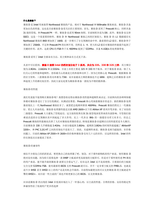
什么是赛扬D赛扬D是Intel用来接替Northwood赛扬的产品,相对于Northwood和Willmatte赛扬来说,赛扬D具备更加出色的性能,这也是目前赛扬D备受关注的主要原因。
首先,赛扬D采用了Prescott核心,同样具备31级的管线。
和Prescott P4一样,赛扬D也采用90nm制程,目前制程步进为D0。
此外,赛扬D也支持SSE3,这是一个很重要的特性。
赛扬D和Northwood赛扬之间的区别很大:赛扬D的L1 数据缓存从Northwood赛扬的8KB增加到了16KB,进一步增大了分支预测的命中率。
最重要的L2缓存,赛扬D终于增加到了256KB,不过和Prescott P4的比例不变,仍然是1:4。
更大的L2缓存对赛扬的性能提升起到了关键的作用。
此外,这款CPU的FSB终于从400MHz提到了533Mhz,具备4.1GB/s的处理器带宽。
赛扬D采用了Intel全新命名方法,其主频和命名方式见下表:从表中可以看到,赛扬D按照Intel的档次划分处于3系列,共分为335、330和325三种,其主频分别为2.8GHz、2.66GHz和2.53GHz。
目前上市的主要是325和330两个版本。
对于赛扬D来说,除了人们关心它的性能和超频性,恐怕最关心的就是它的热量和功率了,因为它的核心是Prescott。
根据赛扬D 的官方资料,三款赛扬D的功率都为73W,而目前最高主频的赛扬也不过68W,超频之后的赛扬D功率和温度上升的都比较厉害,因此大家还是要为赛扬D准备一款较为不错的散热器。
赛扬D的性能我们究竟值不值得购买赛扬D呢?我想恐怕还得由赛扬D的性能和超频性来决定。
目前国内的各种网络媒体都对赛扬D进行了全方位的测试。
从测试结果看,Prescott核心用来做赛扬非常适合。
新的赛扬D处理器表现比上一代Northwood赛扬好多了,就算把总线频率降到400MHz,Prescott赛扬仍然比上一代赛扬好。
赛米控丹佛斯 SEMITRANS 3 IGBT模块 SKM600GB12E4D1 数据表

Absolute Maximum Ratings Symbol Conditions Values UnitIGBTV CES T j = 25 °C 1200 V I C T j = 175 °CT c = 25 °C 860 A T c = 80 °C702 A I Cnom 600 A I CRM1800 A V GES -20 (20)V t psc V CC = 800 V V GE ≤ 15 V V CES ≤ 1200 VT j = 150 °C10 μs T j-40 (175)°C Inverse diodeV RRM T j = 25 °C1200V I F Continuous DC forward current 600A I FRM 1200A I FSM 10 ms, sin 180°, T j = 25 °C2736A T j-40 ... 175°C Module I t(RMS)500 A T stg module without TIM-40 ... 125 °C V isolAC sinus 50 Hz, t = 1 min4000VCharacteristics Symbol Conditions min. typ. max. UnitIGBTV CE(sat)I C = 600 A V GE = 15 V chiplevel T j = 25 °C 1.80 2.05 V T j = 150 °C 2.05 2.42 V V CE0chiplevel T j = 25 °C 0.80 0.90 V T j = 150 °C 0.75 0.80 V r CE V GE = 15 V chiplevelT j = 25 °C 1.67 1.92 mΩ T j = 150 °C2.2 2.7 mΩ V GE(th)V GE = V CE , I C = 24 mA55.86.5 V I CES V GE = 0 V, V CE = 1200 V, T j = 25 °C5mA C ies V CE = 25 V V GE = 0 Vf = 1 MHz37.2 nF C oes f = 1 MHz 2.32 nF C res f = 1 MHz2.04 nF Q G V GE = - 8V ... + 15 V 3400 nC R Gint T j = 25 °C 1.3 Ω t d(on)V CC = 600 V I C = 600 AV GE =+15/-15V R Gon = 1.8 Ω R Goff = 1.2 Ωdi/dt on = 8050 A/µs di/dt off = 4100 A/µs dv/dt = 3500 V/µs L s = 25 nH T j = 150 °C 175 ns t r T j = 150 °C 75 ns E on T j = 150 °C 55 mJ t d(off)T j = 150 °C 530 ns t f T j = 150 °C 120 ns E off T j = 150 °C80mJ R th(j-c)per IGBT0.049K/W R th(c-s)per IGBT, (λgrease = 0.81 W/(m*K))0.032K/WIGBT4 ModulesSKM600GB12E4D1Features*∙IGBT4 = 4th generation medium fast trench IGBT (Infineon)∙ CAL4HD = 4th generation high density (HD) CAL-diode optimized for low static losses∙ Insulated copper baseplate using DBC technology (Direct Bonded Copper)∙ Increased power cycling capability ∙ With integrated gate resistor∙ For higher switching frequencies up to 8kHz∙ UL recognized, file no. E63532Typical Applications∙ AC inverter drives ∙ UPS∙ Electronic welders ∙ Wind power ∙ Public transportRemarks∙ Case temperature limited to T c = 125°C max, recomm.T op = -40... +150°C, product rel. results valid for T j = 150°C ∙ Max. operating DC link voltage limited to 800VGBSEMITRANS 3Characteristics Symbol Conditions min. typ. max. UnitInverse diodeV F = V EC I F = 600 A V GE = 0 V chiplevel T j = 25 °C 1.80 2.13 V T j = 150 °C 1.83 2.17 V V F0chiplevel T j = 25 °C 1.19 1.40 V T j = 150 °C 0.97 1.10 V r F chiplevelT j = 25 °C 1.02 1.21 mΩ T j = 150 °C1.44 1.79mΩ I RRM V CC = 600 V I F = 600 AV GE = -15 Vdi/dt off = 9200 A/µs T j = 150 °C 680 A Q rr T j = 150 °C130 µC E rr T j = 150 °C 60mJ R th(j-c)per diode0.095K/W R th(c-s)per diode, (λgrease = 0.81 W/(m*K))0.039 K/W ModuleL CE 15nH R CC’+EE’measured per switchT j = 25 °C0.55mΩ T j = 150 °C0.85 mΩ R th(c-s)1calculated without thermal coupling (λgrease =0.81 W/(m*K)) 0.0088 K/W R th(c-s)2including thermal coupling,Ts underneath module (λgrease =0.81 W/(m*K)) 0.014K/W M s to heat sink M63 5 Nm M t to terminal M62.55 Nm -Nm w325 gSEMITRANS ® 3 IGBT4 ModulesSKM600GB12E4D1Features*∙IGBT4 = 4th generation medium fast trench IGBT (Infineon) Exciter module∙ CAL4HD = 4th generation (HD) CAL-diode optimized for low static losses∙ Insulated copper baseplate using DBC technology (Direct Bonded Copper)∙ Increased power cycling capability ∙ With integrated gate resistor∙ For higher switching frequencies up to 8kHz∙ UL recognized, file no. E63532Typical Applications∙ AC inverter drives ∙ UPS∙ Electronic welders ∙ Wind power ∙ Public transportRemarks∙ Case temperature limited to T c = 125°C max, recomm.T op = -40... +150°C, product rel. results valid for T j = 150°C ∙ Max. operating DC link voltage limited to 800VGBFig. 1: Typ. output characteristic, inclusive R CC'+ EE'Fig. 2: Rated current vs. temperature I C = f (T C )Fig. 3: Typ. turn-on /-off energy = f (I C ) Fig. 4: Typ. turn-on /-off energy = f (R G )Fig. 5: Typ. transfer characteristic Fig. 6: Typ. gate charge characteristicFig. 7: Typ. switching times vs. I C Fig. 8: Typ. switching times vs. gate resistor R GFig. 9: Transient thermal impedance Fig. 10: Typ. CAL diode forward charact., incl. R CC'+ EE'Fig. 11: Typ. CAL diode peak reverse recovery current Fig. 12: Typ. CAL diode peak reverse recovery chargePinout and DimensionsGBThis is an electrostatic discharge sensitive device (ESDS), international standard IEC 60747-1, chapter IX.*IMPORTANT INFORMATION AND WARNINGSThe specifications of SEMIKRON products may not be considered as guarantee or assurance of product characteristics ("Beschaffenheitsgarantie"). The specifications of SEMIKRON products describe only the usual characteristics of products to be expected in typical applications, which may still vary depending on the specific application. Therefore, products must be tested for the respective application in advance. Application adjustments may be necessary. The user of SEMIKRON products is responsible for the safety of their applications embedding SEMIKRON products and must take adequate safety measures to prevent the applications from causing a physical injury, fire or other problem if any of SEMIKRON products become faulty. The user is responsible to make sure that the application design is compliant with all applicable laws, regulations, norms and standards. Except as otherwise explicitly approved by SEMIKRON in a written document signed by authorized representatives of SEMIKRON, SEMIKRON products may not be used in any applications where a failure of the product or any consequences of the use thereof can reasonably be expected to result in personal injury. No representation or warranty is given and no liability is assumed with respect to the accuracy, completeness and/or use of any information herein, including without limitation, warranties of non-infringement of intellectual property rights of any third party. SEMIKRON does not assume any liability arising out of the applications or use of any product; neither does it convey any license under its patent rights, copyrights, trade secrets or other intellectual property rights, nor the rights of others. SEMIKRON makes no representation or warranty of non-infringement or alleged non-infringement of intellectual property rights of any third party which may arise from applications. Due to technical requirements our products may contain dangerous substances. For information on the types in question please contact the nearest SEMIKRON sales office. This document supersedes and replaces all information previously supplied and may be superseded by updates. SEMIKRON reserves the right to make changes.。
- 1、下载文档前请自行甄别文档内容的完整性,平台不提供额外的编辑、内容补充、找答案等附加服务。
- 2、"仅部分预览"的文档,不可在线预览部分如存在完整性等问题,可反馈申请退款(可完整预览的文档不适用该条件!)。
- 3、如文档侵犯您的权益,请联系客服反馈,我们会尽快为您处理(人工客服工作时间:9:00-18:30)。
Symbol PD
Limits
±25 ±25 16 400
150
Thermal Resistance Junction−to−Ambient
RΘJA
833
Lead Solder Temperature − Maximum (10 Second Duration)
TL
260
Junction and Storage temperature range
V
CESDBLC5V0D5
BH
5.0
0.1 5.8 7.8 1.0
12
*Other voltages available upon request. 2. VBR is measured with a pulse test current IT at an ambient temperature of 25℃.
C(pF)@ VR=0V,f=1MHz
Typ 12
A,Dec,2011
【南京南山—领先的片式无源器件整合供应商】
样品申请单
南山联系资料
总机:025-52188228 技术支持:025-84712971 客服:400-888-5058 传真:025-84710486 电邮:Tech@
【领先的片式无源器件整合供应商—南京南山半导体有限公司】
JIANGSU CHANGJIANG ELECTRONICS TECHNOLOGY CO., LTD
SOD-523 Plastic-Encapsulate Diodes
CESDBLC5V0D5 ESD Protection Diodes
ELECTRICAL CHARACTERISTICS (TA=25℃ unless otherwise noted)
Device*
VRWM
IR(μA)
VBR(V)@IT
Device
IT
(V) @VRWM (Note2)
Marking
Max Max Min Max mA
VC @IPP=5A
FEATURES z Reverse working (stand-off) Voltage: 5.0 V z Low Leakage z Response Time is Typically < 1 ns z ESD Rating of Class 3 (> 16 kV) per Human Body Model z IEC61000−4−2 Level 4 ESD Protection
全符合要求,也不承诺一定按期交出。
跟进记录
□已联系客户
□ 已中止进行 已建议生产
□ 中止原因描述: □ 已发送样品/日期
□ 客户已签收/日期
第1页共1页
ELECTRICAL CHARACTERISTICS (TA = 25°C unless otherwise noted)
Symbol
IPP VC VRWM IR VBR IT
Parameter
Maximum Reverse Peak Pulse Current Clamping Voltage @ IPP Working Peak Reverse Voltage Maximum Reverse Leakage Current @ VRWM Breakdown Voltage @ IT Test Current
Maximum Ratings @TA=25℃
Parameter
IEC61000−4−2(ESD) ESD voltage
Air Contact Per Human Body Model Per Machine Model
Total power dissipation on FR-5 board (Note 1)
Tj, Tstg
-55 ~ +150
Stresses exceeding Maximum Ratings may damage the device. Maximum Ratings are stress ratings only.
Functional operation above the Recommended. Operating Conditions is not implied. Extended exposure to
客户基本资料
公司名称 联系方式 收货地址 生产产品
联络人
电话:
姓名: 电话:
传真:
职务: 手机:
网址: □生产型企业
□贸易商
□技术 电邮:
□采购
□其他
样品明细资料
元器件名称 型号及封装
单机用量 申请数量 备注
预计生产情况
预计小批量生产日期:
规模生产日期:
样品申请日期:
样品申请流程
1、请详细、全面、真实填写上列各项。表格不够填写,可自行复制。 2、请以附件的形式将该文档通过 E-mail 发送,并请将此单打印盖章后,传真至:025-84710486。 3、公司将根据客户所填信息并综合相关情况,由样品小组负责确定该样品申请单是否执行及如何执行。 4、收到样品申请单并经审核通过后,南京库有现货2个工作日内发出;如需订货,交期3-4周,非常规品顺延1-2周。 5、样品免费,运费到付(一般选择顺丰快递);样品数量:单个型号5~20pcs, 或根据 BOM 表清单按2~5套提供。 6、说明:接单后,样品小组将努力跟进,但由于原厂生产等环节存有不确定因素,我们无法保证样品数量、型号完
are exposed to ESD. Because of its small size, it is suited for use in
1
cellular phones, MP3 players, digital cameras and many other portable
applications where board space is at a premium.
SOD-523
DESCRIPTION
2
The CESDBLC5V0D5 is designed to protect voltage sensitive
components from ESD. Excellent clamping capability, low leakage,
and fast response time provide best in class protection on designs that
stresses above the Recommended Operating Conditions may affect device reliability.
1. FR−5 = 1.0 x 0.75 x 0.62 in.
Unit
KV KV V mW ℃/W ℃ ℃
【领先的片式无源器件整合供应商—南京南山半导体有限公司】