How to Map a Network Drive
导航系统3引导手册说明书

IntroductionManual OverviewThe manual is divided into the following sections:•Getting started - A basic introduction that discusses the controls and how tocommunicate with the system.•Entering a destination - How to enter an address or locate a point of interest(POI).•Driving to your destination – Anexplanation of the map features,guidance, and cautions.•Information features - V oice help, trip computer, calendar, and calculator.•System Set-up - How to set up and tailor the system for your personal use and add Personal Addresses.The back of this manual contains:•Frequently Asked Questions (FAQs)•Troubleshooting guide•Glossary of terms•V oice command list System OverviewThe navigation system receives signalsfrom the global positioning system (GPS),a network of 24 satellites in orbit aroundthe earth. By receiving signals from severalof these satellites, the navigation systemcan determine the latitude, longitude, andelevation of your vehicle.In addition, a gyroscopic yaw sensor and avehicle speed sensor in your vehicle keeptrack of the direction and speed of travel atall times.The navigation system applies this location,direction, and speed information to themaps and calculates a route to thedestination you enter. As you drive to thatdestination, the system provides map andvoice guidance.The navigation system is easy to use. Thelocations of many places of business andentertainment are already entered in thesystem. You can select any of them as adestination by using the touch screen orvoice control.There are several ways to enter adestination, such as by point of interest(POI), by address, by phone number, andby selecting it from the map. The last 50destinations are saved for reuse at a laterdate. The system also allows you to store ahome address to simplify returning homefrom your destination.Accessories PrecautionsIf you plan to install electronic componentssuch as vehicle locators, remote starters,additional amplifiers, or other audio com-ponents ensure that they are not located nearthe navigation control unit under the frontpassenger's seat or near the navigation displayin the dash. Signal noise emanating from thesedevices can cause intermittent disruption of thenavigation system.NOTE: Do not place any solid objects onthe dash. The GPS antenna is locatedunder the dash, and reception can beblocked or degraded.sophisticated location system with voicecontrol that uses satellites and a mapdatabase to show you where you are and tohelp guide you to a desired destination.Your navigation system is a highly-34Important Safety InformationThe navigation system can distract your attention from the road if you focus on the screen or operate the system’s controls while driving.Enter as much information as possible into the system before you begindriving, or when the vehicle is stopped.Then, as you drive, listen to the audio instructions and use voice commands when possible.While driving, do not look at the screen or operate the system controls for more than a second or so at a time, and only after deciding you can do so safely.Pull to the side of the road if you need more time to look at the screen or operate the controls.The navigation system is designed to provide route information to help you reach your destination. However, this route guidance may sometimes conflict with current road conditions such as street closures, road construction,detours, and out-of-date map data.Additionally, the system itself has certain limitations (see page 66).Therefore, you must verify the audio and visual route information provided by the system by carefully observing the roadway, signs and signals, etc. If you are unsure, proceed with caution.Always use your own good judgment,and obey traffic laws while driving.Map OverviewYour navigation system has two kinds of streets: verified (dark colored) and unverified (light colored). Thedifferences between the two types of streets are contrasted in the followingchart.Introduction“Verified” Road5IntroductionWhen displayed Street color Map QualityRoutingdifferences CautionsGuidance voice Time and distance“to go”Verified streets (dark colored)These roads are found within metropolitan areas, and include interstate freeways and major roadsconnecting cities.Shown on daytime map screen as black or red, such as interstate freeways.The database vendor has verified these streets.Information like turn restrictions, average speed, and whether it is a one way street have been gathered and used when creating your route to a destination.While driving to your destination, the displayed route line is solid blue. The system provides voice and map guidance to your destination.There are no pop up boxes urging extra caution during a route. However, because roads constantly change, you are urged to use common sense, and always obey posted traffic restrictions.V oice guidance issues maneuvers such as “In a half mile make a right turn.”The time and distance “to go”, displayed while en-route to a destination, is based on the average speed and distance for the roads used for your route.Unverified streets (light colored)These roads are found in rural areas, and typically include residential streets away from the center of a town.Shown on the daytime map screen as light brown.Your route line is either a blue dotted “vector line”, or a dashed pink/blue line. See the Set-up section “unverified routing” for information on selecting this option, and the routing differences.Regardless of whether the user chooses route guidance, there are cautionary screens before and during the route urging the user to be extra cautions, and obey all traffic restrictions. See the Unverified Routing on page 39.The suffix “if possible” is added to each guidance maneuver.For example: “In a half mile make a right turn, if possible.” Because the average speed of these roads is not known, the time and distance “to go” is based on a fixed average speed of 25 mph for these roads.These streets have not been verified by the database vendor. The system does not contain information about one-way streets, turn restrictions, or the road’s average speed. They are shown on the map for reference and can have errors in map location, naming, and address range.。
DeviceNet系统快速参考说明书

DeviceNet System Quick ReferenceImportant User InformationSolid state equipment has operational characteristics differing from those of electromechanical equipment. Safety Guidelines for Application, Installation, and Maintenance of Solid State Controls (publication SGI-1.1 available from your local Rockwell Automation sales office or online at ) describes some important differences between solid state equipment and hard-wired electromechanical devices. Because of this difference, and also because of the wide variety of uses for solid state equipment, all persons responsible for applying this equipment must satisfy themselves that each intended application of this equipment is acceptable.In no event will Rockwell Automation, Inc. be responsible or liable for indirect or consequential damages resulting from the use or application of this equipment.The examples and diagrams in this manual are included solely for illustrative purposes. Because of the many variables and requirements associated with any particular installation, Rockwell Automation, Inc. cannot assume responsibility or liability for actual use based on the examples and diagrams. No patent liability is assumed by Rockwell Automation, Inc. with respect to use of information, circuits, equipment, or software described in this manual. Reproduction of the contents of this manual, in whole or in part, without written permission of Rockwell Automation, Inc., is prohibited.Throughout this manual, when necessary, we use notes to make you aware of safety considerations.WARNING Identifies information about practices or circumstances that can cause an explosion in a hazardous environment, which may lead to personal injury ordeath, property damage, or economic loss.IMPORTANT Identifies information that is critical for successful application andunderstanding of the product.ATTENTION Identifies information about practices or circumstances that can lead topersonal injury or death, property damage, or economic loss. Attentions helpyou identify a hazard, avoid a hazard, and recognize the consequence.SHOCK HAZARD Labels may be on or inside the equipment, for example, a drive or motor, to alert people that dangerous voltage may be present.BURN HAZARD Labels may be on or inside the equipment, for example, a drive or motor, to alert people that surfaces may reach dangerous temperatures.Table of ContentsTopic PageDesign 3 Select 4 Install 5 Configure 6 193-DNCT Handheld Configuration Device 6Node Commissioning on Your DeviceNet Network 6Starting the 193-DNCT Terminal 7Change Node Number 63 to Node Number 1 8Create the 1756-DNB and 1769-SDN Scanlist by Using AutoScan 9Example: Configure the E1 Overload12Maintain 13 Diagnostics and Troubleshooting 13DesignFor this manual, we are looking at a system with these constraints. They do not represent networkmaximums. The DeviceNet network has these capabilities:•Cable length of 100 m (328 ft)•Maximum of 64 nodes•Power supply limited to 4 A (Class 2)Example Media ConfigurationThis example illustrates the layout of a drop system configuration.For detailed wiring information, refer to the Industrial Automation Wiring and Grounding Guidelines,publication 1770-4.1.SelectUse this table to select the appropriate media for your system. For other media choices, refer to Chapter 6 in the On-Machine Connectivity Catalog, publication M116-CA001.Description Cat. No.DeviceNet handheld configuration terminal 193-DNCTIP20 flat media 1485-P1W100Trunk-line connector, IDC 1485P-K1TG4Drop-line connector, IDC 1485P-K1DL4Terminating resistor, IDC 1485P-K1TR4Terminal block, IDC 1485P-K1TLR4Flat-to-thin round cable converter, IDC 1485P-K1GK45-pin open style connector, IDC 1485P-K1G4-Y5Manual crimp tool 1485A-KCRIMPControlLogix DeviceNet scanner module 1756-DNBCompactLogix DeviceNet scanner module 1769-SDN4-in/2-out block I/O 120V AC relay DSA 100-DNY41R4-in/2-out block I/O 24V DC relay DSA 100-DNY42RAC/DC DIN-rail mount power supply, DeviceNet 4 A 1606-XLDNET4E1 DeviceNet module for 193 E1 plus overload relay 193-EDNPowerFlex DeviceNet communication interface 22-COMM-DThin round cable, 50 m (164 ft) roll 1485-P1C50Terminating resistor 1485A-C2InstallLocate and mount the modules. Follow these steps to crimp the connectors.For thin round media, refer to the DeviceNet Media Design Installation Guide,publication DNET-UM072.Important: •Do not crimp the edge of the connector cover.•Do not crimp at the back of the crimp block.•Be sure to set the connector in the correct orientation.1. Set the center of the connector cover (see arrows) in the center of the crimp block of the crimp tool.2. Crimp the connector until you hear the connector lock into place.Configure193-DNCT Handheld Configuration Device, Revision 2.1 or LaterThe 193-DNCT DeviceNet configuration terminal is a handheld device that can configure, program, retrieve historical data, and monitor DeviceNet components, while directly connected to the network. Commissioning is made simple with the capability to upload, store, and download complete device configurations, while online with the network. This tool also aides in troubleshooting by providing physical layer diagnostics and network bandwidth statistics.Node Commissioning on Your DeviceNet NetworkOnce the DeviceNet media and/or cabling system is installed, you need to assign a unique node number, between 0 and 63, to every device on the DeviceNet network. You can do this by setting the rotary or dip switches or by using the Node Commission function via software or a handheld device. Set each device on the network to the same communication rate: 125, 250, 250, or 500 Kbps.Important: The factory default for each device is 125 Kbps, set to node number 63 with autobaud enabled.Starting the 193-DNCT TerminalAttach and connect the 193-DNCT terminal to the DeviceNet network. This display appears for10 seconds.Important: The DeviceNet configuration terminal is shipped so that when it is placed on a DeviceNet network for the first time, it automatically sets its baud rate to that of thetraffic on the network. Auto Addressing automation assigns an unused network nodeaddress to the terminal.After 10 seconds, a Network Who dialog box similar to the one shown below appears with all nodes and associated devices on the network.Notice that the node number in the upper right corner constantly changes. This shows the node number that the 193-DNCT terminal is currently scanning during the active network browse it is performing.If the Network Who dialog box does not appear after 10 seconds, the 193-DNCT terminal is set to Autobaud Enabled and cannot determine a communication rate as no communication is currently occurring on the network.Follow these steps to disable Autobaud.1. On the 193-DNCT keypad, press ESC .2. Select AutoBaud and press the <Up Arrow> to choose Disable.Follow these steps to set the communication rate to 125 Kbps.1. Press SEL to advance to BaudRate.2. Select BaudRate and press the Up Arrow to choose 125 Kbps.3. Press ESC to exit Setup.Change Node Number 63 to Node Number 1No entry exists for node 1 in the Network Who dialog box because the device is currently at node 63. Follow these steps to change to node number from 63 to 1.1. On the 193-DNCT keypad, press the Down Arrow to scroll through the list and select ‘63 – NoProduct Name’.2. Press Enter to advance to the configuration dialog box.3. Press the Down Arrow to select Tools.4. Press Enter .A dialog box appears with NodeComm selected.5. Press Enter again.The Node Commissioning dialog box appears with BaudRate selected.6. Press SEL to advance to Address and select it.7. To change the Address, press 1 and then Enter .An Apply Changes dialog box appears.Tip: You can use the Up Arrow and Down Arrow to scroll through the node numbers.8. Press SEL and then Enter to complete the node commissioning.After approximately 2 seconds the 193-DNCT terminal re-initializes. In another 10 seconds, the terminal again displays the Network Who dialog box with node 1 now visible.Create the 1756-DNB and 1769-SDN Scanlist by Using AutoScanThe DeviceNet network AutoScan feature allows a scanner to automatically map a network of slave devices into its scanlist without the use of RSNetWorx for DeviceNet software. This greatly improves the ease of setting up a DeviceNet network, especially networks comprised of simple devices.When you enable AutoScan, the 1756-DNB or 1769-SDN scanner module searches for devices on the network that are not yet mapped. Once a qualifying device is found, the scanner adds the device to its scanlist and maps its I/O data into a predefined location in the scanner’s I/O memory table. This location is based on the device’s node address and the mapping size.AutoScan is not enabled initially. You must enable AutoScan so that devices are automatically added to the scanlist whenever the scanner module is in Idle mode. The mapping size provides the scanner module with the number of bytes per node to allocate in the I/O tables. Set the mapping size so that it is higher than the maximum input or output size of every device on the network. If a device found on the network has an input or output size larger than the mapping size you set, it will not be added to the scanlist.In this example, the mapping size is set to 32 bytes per node. The 193-DNCT terminal configures and originates AutoScan from a special menu, created specifically for that purpose.1. Turn the key on the front of the 1756-L63 controller (in slot 2) completely clockwise.This puts the ControlLogix controller into Program mode, which also puts the scanner module into Idle mode.2. In the Network Who dialog box, press the Up Arrow to navigate to and select the first line(0 – 1756-DNB DeviceNet Scanner).3. Press Enter to go to its configuration dialog box.4. Press the Down Arrow to navigate to and select Scanner and press Enter .5. Press the Down Arrow to navigate to and select AutoScan and press Enter .This AutoScan Setup dialog box appears.6. If AutoScan is selected and set to Disable, press the Up Arrow to change to Enable.7. Press SEL to select Mapping and press 3, 2, and then Enter .8. Press SEL and then Enter to save your changes.AutoScan begins and the Active Nodes value increments. When the value reaches a node count of 6, AutoScan is finished and found all 6 nodes on the network.9. Select AutoScan and press the Up Arrow to change to Disable.10. Press SELtwice and then press Enter to save your changes.AutoScan is disabled in the scanner.11. Press ESC three times to return to the Network Who dialog box on the 193-DNCT terminal.12. Turn the key on the front of the 1756-L63 controller (in slot 2) completely counter-clockwise.This puts the ControlLogix controller back into Run mode, which will also put the scanner module into Run mode, provided that the scanner run bit is set by the logic or data table.View the I/O Mapping InformationOnce all of the devices have been added to the scanlist via AutoScan, you can check the I/O data mapping that was generated by AutoScan. The 193-DNCT terminal can view the input and output data sizes along with the input and output data mapping assignments for each device.1. In the Network Who dialog box, press the Up Arrow to navigate to and select the first line(0 – 1756-DNB DeviceNet Scanner).2. Press Enter to go to its configuration dialog box.3. Press the Down Arrow to navigate to and select Scanner and press Enter .4. Press the Down Arrow to navigate to and select ScanList and press Enter .This ScanList dialog box appears.5. Press the Down Arrow to navigate to and select 5 – E1 Plus and press Enter .A dialog box appears with the mapping details of the E1 Plus devices scanlist entry. You cantemporarily disable the 1756-DNB scanner scanlist entry.6. Press SEL to select Mapping.This entry lets you modify the size of the native data location for the controller you are using.For example, the Logix-based controllers use a 32 bit Dword for each location in their data table while some other controllers may use only a 16 bit word. Depending on the native data size of the controller you are using, you may need to modify this entry, to accurately view the data mapping assignments for a device in the scanlist.•The input mapping line displays an 8 to signify an input size of 8 bytes of data going back to the scanner.•The next line displays D40:0 --- D41:31 to signify that the data starts at Dword 40, bit 0 of the input table and continues contiguously to Dword 41, bit 31. Therefore the mapping takestwo complete, 32 bit, Dword locations in the data table. The output mapping line displays a 1to signify an output size of 1 byte of data coming from the scanner.•The last line displays D40:0 --- D40:7 to signify that the data starts at Dword 40, bit 0 of the output table and continues contiguously to Dword 40, bit 7.7. Press the Down Arrow to change the mapping value.Notice the effect this change has on the mapping details.8. Press ESC four times to return to the Network Who dialog box on the 193-DNCT terminal.Example: Configure the E1 OverloadWith your fully wired and operational network, there is usually some configuration required for one or more of the devices, including how the device will behave on the DeviceNet network or how the device will act as its main function. The 193-DNCT terminal can configure and monitor parameters in the devices connected to the network. In this example, the 193-DNCT terminal changes the OverLoad Warning Level parameter in the E1 Plus overload unit.1. In the Network Who dialog box, press the Down Arrow to navigate to and select 5 – E1 Plus.2. Press Enter to go to the E1 Plus configuration dialog box.3. Press the Down Arrow to navigate to and select Params and press Enter.Device parameters can be viewed by Groups of similar functions or as a Numerical Listing.4. Press the Down Arrow to navigate to and select Num List and press Enter.The 193-DNCT terminal now displays parameter 1, the Average %FLA parameter.Important: Additional information is provided at the bottom of the display for each parameter display, including the parameter description (that scrolls continuously), minimum andmaximum values, and if the parameter is read only.5. Press 1, then 7, and press Enter to display parameter 17 (the OL Warning Level configuration).The OL Warning Level parameter 17 displays with a value of 80%.6. Press the SEL , then press 9, 0, and Enter to change the value to 90%.Notice how the configuration value changes to 90% on the display. This value was actually written to the E1 Plus and has been stored into nonvolatile memory within the device.MaintainDiagnostics and TroubleshootingThe 193-DNCT terminal has some diagnostics built in that can be used to troubleshoot a DeviceNet network. These diagnostics include bus voltages, bandwidth utilization percentage, and CAN error counts.1.Press the Down Arrow to navigate to Node 62 This DeviceNet HIM.2. Press Enter to select the HIM.3.Press the Down Arrow to navigate to and select the Network group and press Enter . This dialog box, with similar values, appears on the 193-DNCT terminal.The Max Bus % Load and CAN Errors/Sec parameters are not easily measured by other means and are valuable for troubleshooting the network. The Max Bus % Load parameter shows the maximum network bandwidth that has ever been used. If this value goes too high, communication anomalies could occur on the network due to devices being ‘starved’ for bandwidth. The CAN Errors/Sec parameter is generated if packets are being corrupted on the network, such as due to electrical noise or a bad device. This value, which should be zero on a healthy network, is a good barometer of the general health of the DeviceNet packet-delivery mechanism.Allen-Bradley, Rockwell Automation, PowerFlex, ControlLogix, CompactLogix, and RSNetWorx for DeviceNet are trademarks of Rockwell Automation, Inc. Trademarks not belonging to Rockwell Automation are property of their respective companies.Publication DNET-QR001A-EN-E – March 2009Copyright©2009 Rockwell Automation, Inc. All rights Reserved. Printed in USA.。
AU2015 The Anatomy of a DWG - 如何创建健康的Drawing内部和外部的

Key learning objectives
At the end of this class, you will be able to:
Develop an effective argument to get management to agree that CAD standards are important How to develop a Standard Who will champion it Learn how to include key people
Disclaimer: the above is the author's personal opinion and is not the opinion or policy of his employer or of the little green men that have been following him all day.
Disclaimers were one of the original uses of signature files. Wouldn't it be a nice world if we didn't need to disclaim everything? Sheesh.
Warning: Spelling errors in this message are the product of a poor school system. Pay teachures more than athletes.
Spotted on a button: 'Ambivalent? Well, yes and no....'
The facts expressed here belong to everybody, the opinions to me. The distinction is yours to draw...
无人驾驶的英语课件PPT

Other potential applications include long haul trucking, public transportation, and even self driving taxis or shared mobility services
3D Reconstruction
The creation of a 3D model of the environment from sensor data to provide more accurate representation of the scene
Path planning technology
Application scenarios for autonomous driving
Autonomous driving has the potential to revolutionize transportation, particularly in urban areas where traffic congestion and pollution are major issues
Techniques used to regulate the vehicle's velocity, acceleration, and steel angle to achieve desired performance and safety standards
Risk Assessment
The evaluation of potential hazards and their associated risks to inform decision making processes
如何在Windows11中映射网络驱动器
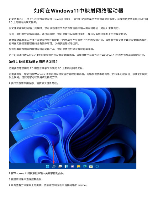
如何在Windows11中映射⽹络驱动器如果您有不⽌⼀台 PC 连接到本地⽹络(Internet 连接),在它们之间共享⽂件夹资源会很⽅便。
这样做将使您能够访问不同PC 上的相同共享⽂件夹。
当⽂件夹在本地⽹络上共享时,您可以通过在⽂件资源管理器中输⼊其⽹络地址(路径)来找到它。
但是,最好映射⽹络驱动器。
通过这样做,您可以像访问本地计算机⼀样访问备⽤计算机上的共享⽂件夹。
映射驱动器为访问存储在本地⽹络中不同 PC 上的共享⽂件夹提供了⽅便的快捷⽅式。
当您为共享⽂件夹建⽴映射驱动器时,它将在⽂件资源管理器的此电脑中可见,以便快速轻松地访问。
包含与其前⾝相同的映射⽹络驱动器⼯具,您可以使⽤它来设置映射驱动器。
您还可以通过Windows 11中的命令提⽰符设置映射驱动器。
这就是使⽤这些⽅法在Windows 11中映射⽹络驱动器的⽅式。
如何为映射驱动器启⽤⽹络发现?您需要在您使⽤的 PC 和包含共享⽂件夹的 PC 上都启⽤⽹络发现。
更重要的是,您必须在Windows 11中启⽤⽹络发现才能映射驱动器。
⽹络发现使本地⽹络上的设备可被发现,以便它们可以相互找到。
这就是您可以启⽤该功能的⽅法。
1.要打开搜索实⽤程序,请按放⼤镜任务栏。
2.在Windows 11的搜索框中输⼊关键字控制⾯板。
3.在搜索结果中选择控制⾯板。
4.单击查看⽅式菜单上的类别。
然后在控制⾯板中选择⽹络和 Internet。
5.选择⽹络和共享中⼼以打开该⼩程序。
6.接下来,单击控制⾯板左侧的更改⾼级共享设置。
7.选择打开⽹络发现选项。
8.此外,选择打开⽂件和打印机共享单选按钮。
9.单击保存更改按钮以应⽤新设置。
如何设置共享⽂件夹?您只能包括映射驱动器的共享⽂件夹。
共享⽂件夹时,它将具有本地⽹络路径,您可以在⽂件资源管理器中输⼊以查看它。
这是在Windows 11中设置享⽂件夹的⽅法:1.按键 +键盘快捷键调出⽂件资源管理器。
WindowsE2.右键单击要共享的⽂件夹,然后选择Properties。
戴尔 DR4000 磁盘备份设备上设置 Veeam说明书
Setting up Veeam on theDell™ DR4000 Disk Backup ApplianceA Dell Technical White Paper© 2012 Dell Inc. All Rights Reserved. Dell and the Dell logo, and other Dell names and marks are trademarks of Dell Inc. in the US and worldwide. Veeam is a trademark of Veeam.Table of contentsExecutive Summary (4)1Install and Configure the DR4000 (5)2Configure the Backup Server (12)3Set up Veeam (14)4Set up the DR4000 Cleaner (19)5Monitoring Dedupe, Compression & Performance (20)Executive SummaryThis paper provides information about how to set up the Dell DR4000 as a backup to disk target forVeeam® Backup & Replication™ software. This paper is a quick reference guide and does not include allDR4000 deployment best practices.See the DR4000 documentation other data management application best practices whitepapers foradditional information.1Install and Configure the DR40001.Rack and cable the DR4000 appliance, and power it on.2.Log into iDRAC using the default address 192.168.0.1, user name root, and the password calvin.unch the virtual console.4.Once the virtual console is open, log in to the system as user administrator and the passwordSt0r@ge! (The “0” in the password is the numeral zero.).5.Set the user-defined networking preferences.6.View the summary of preferences and confirm that it is correct.7.Log into the DR4000 administrator console, using the IP address you just provided for theDR4000, user administrator and the password St0r@ge! (The “0” in the password is the numeral zero.).8.Join the DR4000 to Active Directory.a.Select Active Directory in the tree on the left hand side of the dashboard.b.Enter your Active Directory credentials.9.Create and mount the container.a.Select Containers in the tree on the left side of the dashboard, and then click the Create linkat the top of the page.b.Enter a Container Name and select the Enable CIFS check box.c.Select the client access credentials preferred.For improved security, Dell recommends adding IP addresses for the following (Not all environments will have all components):-Backup console (Veeam Server)-Hyper-V hosts (on-host proxy for Hyper-V environments)s -Off-host proxies (for Hyper-V environments)-Backup proxies (for vSphere environments)d.Click Create a New Container.e.Confirm that the container was added.f.Click Edit, and write down the container path, which you will use later to target the DR4000.g.Click Cancel to exit.2Configure the Backup Server1.Log into the media server and click on Start My Computer.2.Click Map network drive.3.For Folder, enter the path to the container on the DR4000.4.Select the Reconnect at logon check box.5.When prompted, enter the DR4000 login credentials.The DR4000 container is now mounted to your backup server.3Set up Veeam1.Open the Veeam Backup & Replication console.2.Click the Backup Infrastructure section, right-click on Backup Repositories, and select AddBackup Repository.3.Enter a name that is self-documenting, such as “CIFS-DR4000-Deduplication,” to indicate thedevice, protocol and feature of the repository.4.Select Shared folder.5.For Shared folder, enter in the name of the DR4000 (or TCP/IP address used above) and the sharename, and then click Next.6.Configure the repository wizard to note that the DR4000 is a deduplication target. Click theadvanced button and select the additional option for “Aligning backup file data blocks” (fixedlength write). Optionally select the decompress value. The decompress option will make theDR4000 do all of the compression.All other options for the new repository wizard are independent of anything related to theDR4000.7.Create a new backup job in the Veeam Backup console, for either Hyper-V or vSphere; the optionsspecific to the DR4000 are the same.8.Select one or more virtual machines, folders, datastores, resource pools, vApps, SCVMM clusters,etc. for the backup.9.Ensure that the repository for this job is the DR4000.10.On the storage wizard of the backup job, click the Advanced button to check a number ofimportant settings.11.Ensure the backup job is running in Incremental mode, and avoid the rollback transformationoption. This is a default for new jobs.12.Change the compression engine to Dedupe-friendly in the storage tab of the advanced settings.The deduplication option to local target will perform deduplication by Veeam at 1 MB, landing on the DR4000 for additional deduplication and compression.All other options are independent of the backup target.4Set up the DR4000 CleanerOnce all the backup jobs are setup the DR4000 cleaner must be scheduled. The DR4000 cleaner shouldrun at least 6 hours per week when backups are not taking place, generally after a backup job hascompleted.Performing scheduled disk space reclamation operations are recommended as a method for recoveringdisk space from system containers in which files were deleted as a result of deduplication.5Monitoring Dedupe, Compression & Performance After backup jobs have run the DR4000 will track Capacity, Storage Savings and Throughput on theDR4000 dashboard. This information is valuable in understanding the benefits the DR4000.21 Setting up Veeam on the Dell™ DR4000 Disk Backup Appliance。
FedEx Ship Manager软件安装指南说明书

FedEx Ship ManagerThank you for selecting FedEx Ship Manager software.Verify that your PC meets the minimum hardwareand system requirements.•Pentium ®II 266 MHz recommended (Pentium 133 MHz minimum).•128 MB RAM recommended.•150 MB disk space.•Microsoft ®Windows ®2000 or Microsoft ®Windows ®XP .•LAN or DSL Internet access recommended (dial-up telephone lineaccess minimum).1Steps to complete installation•4X CD-ROM or higher.•31/2'' floppy drive.•Microsoft ®Internet Explorerv.6.0.• Available port if you areusing a thermal printer.•Laser and/or inkjet printerfor reports and labels.•Minimum screen resolutionof 800 x 600 pixels.Attention:Microsoft Windows 2000 customers If Microsoft Windows 2000 with Service Pack 4 (SP4) is installed on your PC, you may experience issues communicating to FedEx. If you experience communications issues, please contact Microsoft and reference Microsoft Knowledge Base Article — 824301.2Speed up installation and registration by havingthese items on hand.•If using LAN Internet Access to connect to FedEx, contact your network administrator before installing FedEx Ship Manager. For important information regarding LAN configuration, refer to Network Administrator Tips on page 5 of this guide.•Dialing prefix (typical usage for this field is to dial 9 for an outside line).•Your 9-digit FedEx account number.•Employer Identification Number (EIN) or tax ID, if you ship international packages (optional).•FedEx Signature Release Number for nonresidential shipments (optional).Network Administrator Tips• To install FedEx Ship Manager, you must have administrator privileges on the PC on which you are installing the software. FedEx Ship Manager requires administrator privileges to update the FedEx registry. You do not, however, need administrator privileges to use FedEx Ship Manager.• You must have port 443 open for outbound and secured communication to FedEx and port 80 open for Web browsing.3Install the printer to print shipping labelsand reports.First, a printer must be installed on the local drive for printing shipping labels and reports. If you are using a network printer, install it as a local printer on your system using Add Printer in the Microsoft Printers Folder and map it to the network printer’s address.For important information regarding LAN configuration, refer to Network Administrator Tips on page 5.Install FedEx Ship Manager software.Depending on your operating system, actual screens may vary and some of the screens may not be described below. In this case, follow the on-screen instructions.1.During the installation, turn off any virus protection or firewall programs on your PC. These programs may interfere with the FedEx Ship Manager installation. Close all other open files and programs. Then insert the FedEx Ship Manager CD into your CD-ROM drive.2.The FedEx Ship Manager Welcomescreen displays. If it does not,double-click My Computer onyour desktop, and double-clickthe CD-ROM drive.3.Click Next.44.Read the FedEx Ship ManagerLicense Agreement. Click Yes toagree and continue the installation.If you select No, the setupprogram closes and the softwaredoes not install.5.Click Next to install FedEx ShipManager in the default destination folder.6.If you use FedEx Ship Manager at multiple PCs on your local area network, check Network Component. Once the central PC (server) is installed and registered, map the other PCs (clients) to the installation location on the central PC. Refer to Client Installation.7.Click Next to add icons to the FedEx Ship Manager program folder.8.The setup program prompts you to install the Java 2 Runtime Engine, if Java is not already installed. Click Yes to install Java and follow the on-screen directions.9.Read the Sun Microsystems, Inc.,Binary Code License Agreement.Click Yes to agree and continuethe installation. If you click No,the setup program closes andthe software does not install.10.Click Next to install Java 2Runtime in the default destination folder.11.Click Next. Microsoft Internet Explorer is selected as thedefault browser.12.The Install Shield Wizard installs Java 2 Runtime on your PC.13.Click Finish to complete the installation and restart your PC.You must restart your PC before registering FedEx Ship Manager. Now you are ready to register FedEx Ship Manager. Before proceeding, make sure your PC can connect to the Internet or to your dial-up telephone line.Steps to complete registration5Launch the software.From the desktop, double-click the FedEx Ship Manager icon tostart the application.6Configure your printer(s).1.From the FedEx Ship Manager Registration screen, clickNext to display the FedEx Ship Manager PrinterConfiguration screen.2.Click one of the printer optionsfor shipping FedEx packages,and click Next.3.Select your report and labelprinters, and click Next todisplay the FedEx ShipManager CommunicationConfiguration screen.Note:If you want to use a printer that is not displayed in the list of printers, make sure the printer driver is installed on your local drive.7Configure software communications.1.From the FedEx ShipManager CommunicationConfiguration screen,click Next.2.Click one of the availableoptions to indicate yourcommunications connection.3.If you have a LAN or ISPand use a proxy server,click the check box forusing a proxy serverand enter the proxyinformation provided byyour network administrator.4.Click Next.If you clicked Iwill use my LAN or ISPto communicate withFedEx, skip steps 5-7.5.For dial-up communication,the FedEx Dial UpPreferences screendisplays. The option I wantto use FedEx Dialup is already checked for you to use a dial-up telephone line.6.Select the name of your modem from the drop-down menu and customize any dialing properties. If you need assistance, contact your network administrator.7.Click Next to display the FedEx Ship Manager Customer Information screen.8Connect to FedEx to complete registration.1.From the FedEx ShipManager CustomerInformation screen, enteryour account information.For registration to besuccessful, all fields,including contact name,complete address andtelephone number,require entries.2.Click Next to continueregistration.Information for International Shipping and FedEx Signature Release.1.You must enter an EmployerIdentification Number(EIN) or tax ID to sendinternational shipments.However, you do not haveto enter this information forsoftware registration. Youcan add it later using theSender database.2.FedEx Signature Release isoptional for nonresidentialshipments. You can add itlater using the Sender database.Refer to the FedEx Ship Manager online Help for additional information about these options.This step is optionalConnect to FedEx to complete registration.1.Click Finish to complete theonline registration process.Online registration connectsyour PC to FedEx to assign asystem number, downloadtracking numbers, rates,routing files and other importantfiles. After each successfuldownload, the system displays agreen check mark. Downloading information may take a few minutes. Thank you for your patience.9Congratulations!You are ready to startshipping with FedExShip Manager!Please record your systemnumber on page 1. Referto the number whencontacting FedEx forhelp or support.10Next steps.After you have installed and registered FedEx Ship Manager, you can send shipments, import databases or customize your ship-ping preferences. Shipping preferences speed up shipping by automatically entering information into the correct fields for your shipments so there’s less information for you to select or type.11For information on sendingshipments, importingdatabases, and setting upshipping profiles refer toAt a Glance , included inyour packet.Client installationAfter installing and registering the central PC, map a network drive from the other PCs on the local area network to the installation location of FedEx Ship Manager on the central PC. First, on the central PC, share the drive you want to map to from the client.1.Run Microsoft Windows Explorer.2.On the local disk (C) drive, click Program Files (default folder).3.Click FedEx.4.Right click Ship Manager.5.Click Sharing.6.On the Sharing tab, click Share this folder.7.In the Ship Manager Properties box, Click Permissions.8.FedEx requires that you select Change and Read.Note: You may need a LAN administrator for assistance to make sure permissions are set up in compliance with company procedures and policies.9.Click OK to return to the Ship Manager Properties dialog box.Click OK to finish.Next, on the client PC, map a drive from the client PC to the shared drive on the central PC.1.Run Microsoft Windows Explorer.2.Click Tools.3.Select Map Network Drive.4.Select a drive or use the default drive.5.Browse to the central PC, click the Ship Manager folder,and click OK. The folder name automatically fills in.6.Click Finish on the Map Network Drive dialog box.To finish the installation, on the client PC, follow these steps:1.Open the Network Install folder on the newly mapped drive.2.Double-click the Setup application.3.Follow the on-screen instructions to install FedEx ShipManager. With the exception of the Network Component, the installation screens on the client PC are identical to the screens on the server installation.Refer to the FedEx Ship Manager online Help for additional information.Pentium is a registered trademark of Intel Corporation.Microsoft and Windows are registered trademarks of Microsoft Corporation in the United States and other countries.Java and all Java-based marks are trademarks or registered trademarks of Sun Microsystems, Inc. in the United States and other countries.。
VB API函数大全

Returning an ExitCode parameter from an out of process application
从外部应用程序返回参数
Check if a loggin password and user name are correct
检查当前登录的密码和用户名是不是正确的。
Creating new threads to perform asynchronous tasks
创建一个新的线程执行异步任务
Get and set volume information for a drive
得到和设定驱动器的卷信息
Using the ShellExecute API to send mails and print documents
Show the "File Open" Common Dialog
显示“文件打开”对话框
Converting Class IDs to a Prog IDs and back
转变class ID到一个prog ID
Obtaining the current user name
获得当前用户名
Return the path of the temporary directory
给窗体加上定制的系统菜单
Register Components without using Regsvr32.exe
不使用Regsvr32.exe注册组件
Uncover internal DLL functions with Dependency Walker
公布内部调用的dll函数
Launch a PCs default browser with ShellExecute API