CANcardTools
CANalyzer快速入门的翻译
3.1概述3.2准备工作3.3设置总线3.4发送数据3.5分析窗口3.6使用符号数据3.7数据窗口中信号值的分析3.8图形窗口中的信号响应分析3.9发动机面积仿真分析3.10记录测量3.11评估日志文件3.1概述经营理念如果你开始CANalyze r首次和它的功能和控制仍然对你来说完全是新的,下面的旅行会帮助你熟悉它。
经营理念及其最重要特征。
这次旅行你会先建立一个非常简单的CAN总线,CANalyzer作为发送方和接收方。
在第一步CANalyzer建立CANalyze r配置为数据源,即发射站。
然后你会了CANalyze r分析选项的研究,随后在分析窗口中生成数据。
在复杂的实际系统CANalyzer通常也作为发送器和接收器。
你可以利用程序作为数据源向其他控制器发送数据,但您可以同时使用它来观察、记录和评估CAN上的数据通信量,总线。
3.2准备工作如果你打开CANalyzer出发CANalyze r第一时间与台式机跟踪配置,配置和分析是自动打开的。
图1:配置有三台台式机有各种分析Windows(Windows CANalyzer跟踪、数据、图形和统计窗口)以及显示数据流和数据流的度量设置。
同时允许配置CANalyzer。
您可以通过丝带访问所有程序窗口。
图2:色带,分析和刺激标签测量装置的CANalyzer测量装置的数据流图中包含的数据,左边的来源——用PC卡的符号来象征——以及各种各样的评价。
作为数据接收器的右侧块。
也就是说,数据流是从左到右的。
在各个元素之间绘制连接线和分支以澄清数据流。
在数据流图中,您还可以识别小矩形:。
在这些插入点(热点),你可以插入额外的功能块来操作。
数据流(滤波器、重放或用户定义的函数CAPL程序块)。
分析窗口到达每个评估块的信息显示在分析窗口中。
街区的。
例如,跟踪窗口显示到达跟踪的所有信息。
而图形窗口显示您到达图形的信息。
唯一的例外是日志块,它没有分配一个窗口,而是一个记录到达块的数据的文件。
广成ECANTOOLS软件的软件使用

ECANTools软件使用手册
6
沈阳广成科技有限公司
3、1 保存数据功能与实时保存功能
用户可将当前发送/接收列表中的全部数据保存到本地,保存格式详见下表:
文件类型
文件格式
编辑器
文本文件
.txt
3、4 清除功能
可以清空接收/发送窗口中的数据,以及缓存区中的数据。
3、5 滤波设置
接收滤波设置可设置滤波 ID 或 ID 段,如设置滤波,软件会只显示被设置 的滤波 ID(段),不在滤波范围内的 ID 将会被过滤掉。点击“编辑滤波”,弹出 滤波设置窗口,可以设置滤波范围:
ECANTools软件使用手册
25kb16C0B3
12kbps
2BC07C
⑦自动识别波特率按钮:如您不知道目标总线或设备的波特率,可以选择“波 特率自动识别”,自动识别成功条件:被测设备上电且CAN端为活动状态。
请注意,设置波特率尤其重要,许多客户反映设备连接上之后没有数据,或 总线错误,实为波特率没有设置就直接点击确定打开设备。在这里提示您,无论
ECANTools软件使用手册
4
沈阳广成科技有限公司
A.标准波特率识别截图: ECANTools软件使用手册
5
沈阳广成科技有限公司
B.全范围波特率识别截图: 如果标准波特率识别不到未知节点的波特率,可使用全范围波特率进行进一
步识别。本功能有助于帮助工程师修正新开发设备的波特率偏差。
3、数据接收相关功能
②“打开设备”按钮:点击该按钮,可调取USBCAN设备。若显示“USB 设备打开错误!”请检查①中选择的设备是否正确,设备管理器中的驱动是否安 装正确。
CANcaseXL_Manual_EN
Introduction
1.1.2 Certification
Certified Quality
Vector Informatik GmbH has ISO 9001:2008 certification. The ISO standard is a
Management System globally recognized standard.
Here you can find additional information.
Here is an example that has been prepared for you.
Step-by-step instructions provide assistance at these points.
¼ Windows, Windows XP, Windows Vista, Windows 7 are trademarks of the Microsoft Corporation.
© Vector Informatik GmbH
Version 4.2
-5-
Manual
2 CANcaseXL and CANcaseXL log
In this chapter you find the following information:
2.1 Introduction 2.2 Connectors 2.3 LED Display 2.4 Additional Features on CANcaseXL log
Operating Modes Additional LEDs Piezo Buzzer Memory Card Battery CANcaseXL log Flowchart 2.5 Replacing Piggybacks 2.6 Technical Data
MLC 9000+ 说明书

保修
我们可以担保这些产品在出厂之前,在材料和工艺方面无任何功能缺陷,并且可以担保此类 产品在三年内符合相关说明手册资料中所提到的技术规范。 除此处及上述所提及的保修条例外,无任何其他明示或暗示保修。WEST 不会因任何特殊原 因对该产品的适销性和适用性做任何担保。
限制
对于任何意外损坏、后续损坏、特殊损坏或任何其他损坏,或者除上述所提及的任何维修或 更换之外的成本或费用,供应商概不承担责任。用户必须按照说明安装和维护产品。对于因 腐蚀性而造成的产品损坏,供应商没有保修责任。用户自己对于这些产品与其应用程序的适 用性负责。对于一个有效的保修声明,产品在保修期内进行返修必须向供应商支付运费。产 品必须进行适当包装,以免在运输过程中因静电放电或其他形式的危害导致产品受损。
MLC 9000+ 用户指南
MLC 9000+ 用户指南
59371-1
价格:
£11.00 €15.00 $15.00
ii
59327,第 1 期 – 2003 年 5 月 4 日
本安装、接线和操作手册中的信息可能会有所变动,恕不另行通知。 Copyright © 2004 年 5 月,Danaher ICG,保留所有权利。未经厂商书面许可,不得以任何 形式或通过任何方式在检索系统中复制、传播、改写或存储本出版物的任何部分,或者将本 出版物的任何部分翻译成任何其他语言。 注意:
ii
59327,第 1 期 – 2003 年 5 月 4 日
MLC 9000+ 用户指南
目录
目录
1 2 MLC 9000+ 系统概述 ................................................................................
USBCAN总线适配器(CANalyst-II分析仪)产品说明书
BCAN 总线适配器(CANalyst-II 分析仪)产品说明书
1.4 产品销售清单
ห้องสมุดไป่ตู้
序号 1
名称 适配器主机
2
随机光盘
3
USB 数据线
4
备用接线端子
5
3 寸螺丝刀
数量 1
1
1 1 1
单位 台
张
条 只 支
备注
内含:说明书、USB 驱动、二次开发 库文件、二次开发示例程序源代码、 USB_CAN TOOL 测试软件及源代码、
1.3 典型应用
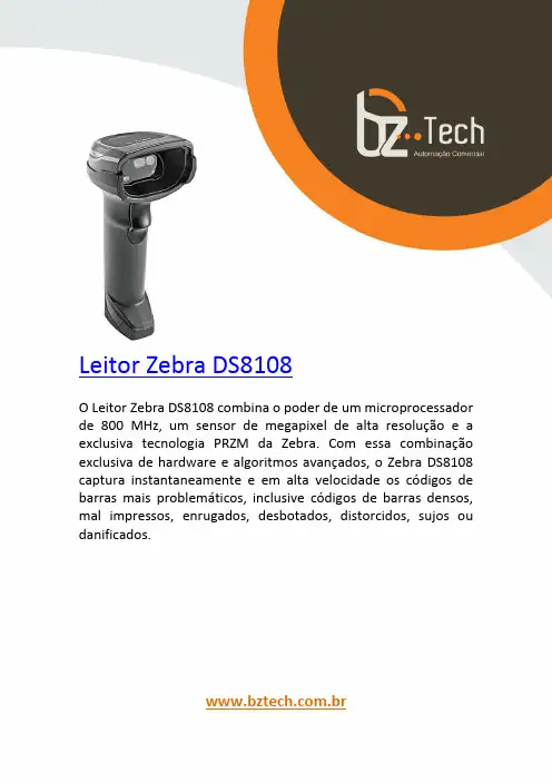
斑马技术公司DS8108数字扫描仪产品参考指南说明书
FCA US LLC车辆扫描工具说明书
SCAN TOOL POSITION STATEMENTFCA US LLC vehicles, systems and components are engineered, tested and manufactured to help protect vehicle occupants. They are engineered to meet or exceed both government-mandated and internal corporate requirements relative to durability, NVH (noise vibration and harshness) and vehicle safety. Use of the Mopar®wiTECH vehicle diagnostic tester (Mopar Scan Tool) is an important part of FCA US vehicle service and maintenance. This tool contains software that aftermarket tools may not contain and can assess whether any FCA US vehicle’s safety and security systems contain active or stored Diagnostic Trouble Codes (DTCs).Safety and security-related systems, such as antilock brakes, supplemental restraint systems (SRS - airbags), occupant restraint controller (ORC), seat belts, active head restraints, forward facing camera and radar, blind spot monitoring, and other automated electronic driver assistance systems, MUST be tested for fault codes (DTCs) that could be active (current) or stored following a collision. Use of the Mopar wiTECH vehicle diagnostic tester is necessary before and after collision repair.ANY of the following conditions could trigger DTCs prior to or during collision repairs, which could result in improper vehicle performance: u Vehicle is involved in an accident or collision, even though the damage may appear minoru Vehicle has been in an accident with or without airbag deploymentu Voltage loss, including battery disconnects and hybrid battery disablingu Significant vehicle disassembly including, but not limited to, bumpers, door handles, headlamps and mirrorsu Interior trim repair or removalu Glass removal and replacement operationsAny repairs performed without using Mopar parts and not following published repair guidelines and procedures may expose current or future vehicle owners and occupants to unnecessary risk.If faults were stored in the DTC memory for any safety or security system, then these systems MUST be serviced according to the repair procedures in Service Information. After performing repairs, recheck the system to determine if any active or stored DTCs remain; if so, take appropriate service action to ensure proper function.SRS AIRBAG SQUIB STATUSMultistage airbags with multiple initiators (squibs) MUST be checked to determine that all squibs were used during the deployment event. The driver airbag (DAB) and passenger airbag (PAB) are deployed by electrical signals generated by the occupant restraint controller (ORC) through the driver or passenger squib circuits (up to 3) to the initiators in the airbag inflators. Typically, all initiators are exhausted and all potentially hazardous chemicals are burned during an airbag deployment event.However, it is possible for only one initiator to be exhausted; therefore, you MUST always confirm that all initiators have been cycled to minimize the risk of improper handling or disposal of potentially live pyrotechnic or hazardous materials. This procedure must be performed using the Mopar wiTECH diagnostic scan tool or at a company such as Collision Diagnostic S ervices that diagnostically remotely scans the vehicle using FCA US scan tools in conjunction with their patented asTech device, to verify the status of all airbag squibs, prior to removing deployed airbags from the vehicle for disposal.u Service Information can be obtained at uMopar wiTECH scan tools can be purchased from https:///Pdf/WiTechOrderForm.pdf©。
商用车CAN网络开发工具列表
商用车CAN网络开发工具序号工具名称功能描述1 CANoe CAN总线系统开发工具,能对系统进行仿真,半物理仿真及测试。
数据库支持对CAN总线报文及信号的符号化访问与显示;通过Statistics, Trace, Data, Graphic和Bus Statistics窗口中分析CAN总线;创建显示和控制面板;可显示、发送、过滤、记录并回放CAN报文;数据记录支持信号触发模式;支持统计功能;支持离线分析;通过CAPL语言实现用户自定义功能。
与Test Automation Editor及DiV a联合使用,可实现通信与诊断的自动化测试验证。
支持Windows 2000/XP/Vista2 CANoe Option .LIN 扩展CANoe功能,从事实现对LIN总线的仿真,半物理仿真及测试。
支持LIN 1.3(TOYOTA标准),LIN 2.0(SAE J2602),LIN 2.1,COOL-LIN (又称COOLING BUS);支持LIN总线描述文件LDF,对LIN总线帧和信号进行符号化访问与显示;可以仿真整条LIN总线上所有节点,并对节点的功能进行建模;创建,编辑,产生LIN总线调度表;交互式控制LIN总线调度表;配置并执行LIN总线从节点一致性测试(分别针对LIN1.3, LIN 2.0, LIN2.1和SAE J2602);配置并执行LIN总线主节点一致性测试(LIN 2.0)3 CANoe Option DiV a DiVa可以基于诊断数据库(CDD文件),为CANoe自动生成全面而详细的诊断测试用例。
操作系统Windows 2000/XP4 CANoe Option J1939扩展CANoe功能,从而实现对J193协议的仿真,半物理仿真及测试。
J1939传输协议的细节跟踪及分析(BAM,CMDT),基于J1939协议的CAPL扩展,在线图形窗口,ECU扫描,默认J1939数据库,J1939节点过滤,J1939节点层DLL,J1939 CAPL代码生成5 CANdelaStudioAdmin创建,修改和管理CANdela诊断模板(CDDT文件)的开发工具,用于将ECU诊断需求实现为机器可读XML-CANdela格式。
KODAK Trūper 3210 3610 型扫描仪 内存升级包 安装说明
A-61687 / 2010 年 6 月部件号7J3505_zh-cn内存升级包的安装说明以下是安装用于柯达 Tr ūper 3210/3610 型扫描仪的内存升级包的说明。
请只用柯达提供的 SODIMM 内存板,否则可能会损坏扫描仪并使质保或服务协议失效。
扫描仪包含 64 MB 的基本内存。
某些扫描工作可能会根据要扫描的文档大小和所需的图像分辨率等因素而需要额外的内存。
例如,A3 之类尺寸的大文档双面扫描或 600 dpi 分辨率的彩色扫描可能需要额外内存。
注意:只有熟悉内存模块(即 PC 上的内存)安装的人员才能安装此升级包。
如果您对安装内存模块感到没把握,请联系服务提供商或系统管理员。
注意:此升级包内含有易受静电放电 (ESD) 损坏的部件和组合件。
需要的工具:十字头螺丝起子。
安装 SODIMM 模块1.关闭扫描仪电源。
2.将电源线从电源插座上拔下并拔下计算机接口电缆。
3.用十字头螺丝起子从接口板上取下两个固定螺钉,并将螺钉放到一边备用。
4.拉把手以取出接口板。
注意:不得将手放入扫描仪内。
5.把 SODIMM 模块之一以倾斜角度插入接口板上的模块连接器之一上。
6.往里推模块直到它发出咔哒声到位,并且模块连接器上的白色突出物夹住SODIMM 模块。
确保您插入SODIMM 模块时,其上的凹槽在左边。
如果凹槽不在该位置,SODIMM 模块就不会正确插入。
7.重复执行步骤 5 至 6 以插入其他 SODIMM 模块。
注意:如需取出 SODIMM 模块,应拉开模块连接器两侧的白色突出物以松开 SODIMM 模块,然后小心地将其拉出。
8.将接口板沿着扫描仪内的导轨滑动到位,将其装回元件内。
9.确认接口板已完全插入并锁定就位,然后用两个固定螺钉将接口板固定住。
10.重新连接电源线和计算机接口电缆,并开启扫描仪电源。
11.打开“用户实用程序”,验证扫描仪是否能识别内存升级。
Eastman Kodak Company343 State StreetRochester, NY 14650 U.S.A.版权所有©Kodak ,2010 年。
can-utils-master的canfdtest用法
can-utils-master的canfdtest用法can-utils-master的canfdtest工具是用来测试和验证CAN FD (Controller Area Network Flexible Data Rate)功能的工具。
它可以用于发送和接收CAN FD 数据帧,并提供了一些选项来设置帧的参数和控制测试过程。
以下是canfdtest的一些常用用法示例:1. 发送CAN FD数据帧:`canfdtest can0 -i -t -f -D 1 -L 1 -n 1000`这个命令将会使用can0接口发送一千个CAN FD数据帧。
其中,-i选项表示使用随机数据填充帧的数据区域,-t选项表示发送数据帧而不是接收数据帧,-f选项表示发送CAN FD数据帧而不是普通CAN数据帧,-D选项表示数据区域的字节长度为1字节,-L选项表示数据区域的比特长度为1比特,-n 选项表示发送1000个数据帧。
2. 接收CAN FD数据帧:`canfdtest can0 -r`这个命令将会使用can0接口接收CAN FD数据帧。
3. 发送和接收CAN FD数据帧:`canfdtest can0 -i -r`这个命令将会使用can0接口发送和接收CAN FD数据帧。
4. 以指定周期发送CAN FD数据帧:`canfdtest can0 -i -f -c 1000`这个命令将会使用can0接口以1毫秒的周期无限循环地发送CAN FD数据帧。
以上只是一些简单的示例,canfdtest还有更多的选项可以用来设置不同的参数和操作。
你可以通过运行`canfdtest --help`命令来获取详细的帮助信息和用法说明。
- 1、下载文档前请自行甄别文档内容的完整性,平台不提供额外的编辑、内容补充、找答案等附加服务。
- 2、"仅部分预览"的文档,不可在线预览部分如存在完整性等问题,可反馈申请退款(可完整预览的文档不适用该条件!)。
- 3、如文档侵犯您的权益,请联系客服反馈,我们会尽快为您处理(人工客服工作时间:9:00-18:30)。
CAN card Tools
URL /motion/cantools/cancard/ contains the link to the card drivers, firmware, and CANview software.
Installing PCI CAN card
Step 1 Load CAN Card Drivers
The files CANcard.inf and copleycan.sys can be placed in a temporary
file such as the desktop for locating with the Windows New Hardware
Found Wizard.
Step 2 Install the CAN Card
Shutdown windows and turn the power off and Install the CAN Card.
Image of PCI CAN card installed in PC slot. Card default has jumper installed for 121 Ohms termination.
Image of CAN1 (channel 0) connected with CAN Kit DB-9 to RJ45 adapter. Note: Last node on CAN network must also have 121 Ohms termination installed.
Turn the power ON and New Hardware will be detected.
Windows will run Found New Hardware Wizard.
Hit Next.
Select Search.
Select Specify a location.
Browse for the Drivers that you have placed on your PC.
If you put them on the desktop then look in the desktop folder.
Select CANcard.inf
Hit Next.
Hit Finish.
Windows Device Manager
The Windows Device Manager can be used to view the CANcard on your PC.
CME2 over Copley CAN Card
CME2 V4.2 or greater, available on the web, can recognize the Copley CAN card if the CAN card drivers are installed.
Step 1 Connecting Drives
Connect the CAN cable from the CAN Card to the first drive and then to any additional drives on the CAN network. Make sure the CAN card and last drive have termination installed. Set the drive node ID with switch (Xenus, AccelNet Panel, StepNet Panel, and Micro Development Kit.) or with jumpers on the signal connector. (AccelNet Micro Panel ACJ J5 +5V to IN6 bit 0 to IN9 bit 4, Xenus Micro Panel XSJ tbd)
Step 2 Connect CME2
Use CME2 tools\Communication Wizard to select CAN communication.
Select Copley, Channel 0 (if cable connected to bottom CAN 1 port), and 1Mbit/s default.
CME2 will scan all 127 possible nodes and identify any found nodes.
CME2 will upload drive parameters and display CAN tree, CAN Network node address, and CANopen State. The CAN Configuration screen can then be used to change settings if required. See CME2 Software manual for more details.
CML and CMO with Copley CAN Card
CML 1.07.20 or greater and CMO 2.1 or greater, available on the web, can recognize the Copley CAN card if the CAN card drivers are installed. See CMO Programmers manual and CANopen Programmers manual for more details.
CAN View
The CANview is now used to download firmware to the CAN Card. The Copley CAN monitor is able to view CAN messages and perform diagnostics on the CANopen network.
View Messages
Monitor bus
The CANview will show us the bus loading. The CAN bus can run well above 90% with no lost messages. If cables are greater than 20 meters at 1 mega bit or if stub lengths are greater than several inches, or if terminating resistors are not properly installed, we may see frame errors. (Tx, Rx, or open handles)
Network Analysis
The CANview will show us the approximate time for sending message to the furthest node and back. The results will be analyzed for good margin, low margin, or possible problem.
CAN Card Firmware
New firmware can be downloaded to the CAN card using the CANview program available on the web in the CANcardTools.zip file. New firmware will be required to take advantage of any new features.
To download firmware, select Tools\CANHardware to view the CAN Hardawre Configuration screen.
Press Update Firmware and select desired firmware.。