MIK0-7SL2中文资料
Leica EM UC7 Leica EM FC7高品质超微切片机说明书

Leica EM UC7Leica EM FC7High Quality Ultramicrotome for Precise Room Temperature and Cryo Sectioning2Highest Quality SectioningHigh quality sectioning of specimens for light, electron, and atomic force microscopy examination has never been easier and more precise. Leica Microsystems introduces its latest specimen preparation technology: the Leica EM UC7 ultramicrotome and theLeica EM FC7 cryo chamber attachment.Leica EM UC7The Leica EM UC7 prepares excellent quality semi- and ultra-thin sections, as well asthe perfectly smooth surfaces required for LM, TEM, SEM, and AFM examination. Theprecision mechanics, ergonomic design, and intuitive layout of the touchscreencontrol unit make the Leica EM UC7 ideal for the highest quality specimen prepa-ration.•E ucentric movement of the stereomicroscope observation system with patenteddesignated positions for specimen approach, for glass and diamond knives.•I n addition to the standard LED illumination for top light and backlight andtransmitted light, the LED spot illumination offers a focused light beam to enhanceobservation, e.g., for cleaning the knife edge and during cryo-sectioning.•T he user can walk away from the instrument during trimming; the combination ofthe fully motorized knife stage and patented AutoTrim function completes and thenstops the trim automatically.•T he ergonomic design provides comfortable, fatigue-free operation for left andright handed users.•E xcellent observation of the section at low water levels and during cryo sectioning,without compromising the user’s ergonomic posture.•T he stereomicroscope offers higher magnifi cation than ever before.•E asy-to-learn, fast operation via touchscreen control and displayed hints.•D ata transfer for reporting user, specimen, knife and storageparameters provides an electronic, paper-free log fi le.•T he operator recognition system makes it easy for multiple users to usethe same instrument. Up to 100 different user/specimen/knife profi lescan be set.Leica Design by Werner Hölbl3Ergonomic Design Comfortable to useLeica Microsystems designed the Leica EM UC7/FC7 with specifi c features that make it a user-friendly, ergonomic instrument provid-ing comfort and minimizing strain for each user. Easy, fast adjust-ments adapt the instrument to accommodate multiple users.Fatigue-free operation is an integral benefi t of the Leica EM UC7/ FC7 design. The Leica M80 stereomicroscope with ErgoWedge accessory adapts the height and angle of the optical head to ad-just perfectly to an individual’s body height and position. Arm rests are attached to the instrument table. These features, in conjunc-tion with the ergonomically arranged control elements, enhance user comfort, even after hours of instrument use.45The Eucentric Movement of the Leica EM UC7 viewing system allows examination of sections, even with a lowered water level e.g. for Lowycryls and dry sections.For accurate approach of the knife towards the specimen with the backlight, the viewing angle must be set according to the type of knife in use.The patented defi ned position marks of the eucentric movement provide maximum approach accuracy either for glass or diamond knife approach.Optimal Positioning of the Optical HeadSection observation with lowered water level without eucentrically moveable stereomicroscope.Section observation with lowered water level with eucentricallymoveable stereomicroscope.Diamond knife approach as seen through the Leica M80 stereo-microscope with backlight illumination.6Advanced FeaturesMotorized knife stageMotorized North-South movement of the knife stage is a unique feature of Leica ultramicrotomes. The additional implementation of motorized East-West movement of the Leica EM UC6 was a logical step forward. Additionally, the E-W quick adjustment buttons on the Leica UC7 controller allow effi cient traversing of the knife. Motorization of the stage has also allowed many useful features to develop hand in hand with it, for example the patented Autotrim mode, E-W measuring function and the automatic approach of the selected knife segment (patent applied).Brightness-controlled LED illuminationLED light sources provide outstanding illumination for top light, backlight, and transmitted illumination. All illumination modes are independently brightness-controlled for the best visual clarity. The additional spot illumination enhances the optical performance of the Leica EM UC7 and provides superior visibility while cleaning theknife edge or trimming the block face, for example.7Effi cient cable controlWhen using a camera system, cables can obstruct the stereo-microscope carrier’s movement. To eliminate this persistent problem, Leica Microsystems provides an integrated cable canal that safely and conveniently guides the cables to the rear of the instrument.Easily activated anti-static functionThe Leica EM CRION ionizer dissipates electrostatic charging that can occur at a specimen’s surface, minimizing static effects associated with climatic changes and the sectioning of certain materials. This adjustable antistatic electrode is a useful ac-cessory for sectioning at room temperature. Adjusting the ioni-zer output is an integral function of the Leica EM UC7 controller; no additional controller is required on the instrument table. The simple press of a footswitch synchronizes and activates the simultaneous operation of the specimen arm motor and the LeicaEM CRION ionizer.8Easy-to-use Touchscreen ControlAll functions of the Leica EM UC7, the Leica EM FC7 cryo chamber and the Leica EM CRION are controlled via touchscreen. A choice of two touchscreen control units are available to operate the ultrami-crotome cryo chamber and ionizer.7” basic touchscreen control unitIndentations in the control panel casing enable the user to locate rou-tinely-used controls that are adjusted while observing the specimen. While viewing the specimen, the user can set the cutting window and step advance and perform many other functions.9Advanced ControlThe innovative advanced touchscreen control unit of the UC7 enables fast and safe alignment of knife and specimen with help fi les and prompts to hand for beginners. Programmable knife and cutting sequences offer signifi cant advantages for automated trimming (AutoTrim).The outstanding performance of the touchscreen is refl ected in its ability to control all necessary components for sectioning. These include the built-in antistatic Leica EM CRION device control, the Leica EM UC7 cryo chamber control, storage of up to one hundred different user, specimen, and knife parameters and a USB con-nection to upload these parameters for reporting. Additionally, every user can save their settings on a USB stick inserted into the Leica EM UC7, enabling the controller to recognize the user assoon the USB stick is connected.10Counter window to toggle between section counter and feedtotalizer, countdown, E-W measuring, and AutoTrim mode.Leica EM FC7 control fi eld appears as soon as the chamber is connected.As soon as the Leica EM CRION ionizer is connected and switched on this window appears to adjust the intensity of the ionizer.To optimize diamond knife usage, up to 100 different knives can be stored. Each knife is divided into a number of segments. The selected segment is approached automatically with the motorized knife stage (patent applied).As soon as the upload button is pressed the grid box window appears and a grid position in the box can be selected, which is automatically reported in the log file.11Protocol Report of Leica EM UC7 Data Log Book. Data transfer for reporting user, specimen, knife, and storage parameters provides an electronic, paper-free log fi le.Leica EM FC7Within minutes the Leica EM UC7 can be equipped with the Leica EM FC7 low tem-perature sectioning system, which incorporates many features and offers a wide range of user benefi ts such as:• T he Leica EM FC7 and Leica EM CRION ionizer controls are both integrated with the Leica EM UC7 control unit to provide easier operation and more workspace.• U sing the advanced touchscreen control, three different cryo-modes are available:– Standard – High gas fl ow - increased GN2 gas fl ow reduces ice contamination below –140°C– Wet sectioning – to set a temperature difference of up to 130°C between knife (– 40°C) and specimen (–170°C), which is useful for, e.g., DMSO applications.• L eica EM CRION ionizer with electrostatic charge and discharge functions con-trolled by footswitches greatly improves the method of cryosection collection.• T he attachable micromanipulator (patent applied) provides precise positioning of the grid to make section collection easier than ever before.• M ultiple lighting angles using the patented LED chamber illumination provide excellent visibility for section manipulation and pick up.• C ontact-free, through-the-wall specimen arm makes the instrument highly stable for chatter-free cryosectioning.• T he optional Cryosphere can surround the Leica EM UC7/FC7 to provide an envi-ronment with a relative humidity of less than 10%. It allows sections to be cut without contamination by ice crystals, which can be a problem at higher humidity.• H eated chamber walls prevent icing over a prolonged working time and enhan-ce user comfort. The GN2 gap between chamber and arm rest ensures a warm surface for the user to rest on.12When the section ribbon needs to be placed on the grid, return to the pre-set grid position can be quickly performed. The ribbon is then attached to the grid using the charge mode of the Leica EM CRION, which is operated by a footswitch. Thus, the specimen adheres to the grid without the need for a section press.As a grid box can be placed near the knife, the micromanipulator can be used to easily place the grid into its storage position.Advanced Cryo-section CollectionLeica EM CRION ionizer and micromanipulatorEspecially for frozen hydrated sectioning or the Tokuyasu method, the Leica EM CRION with electrostatic discharge and charge mode used with the micromanipulator provides outstanding cryo sectioning performance.The micromanipulator easily attaches to the Leica EM FC7 cryochamber, which allows the grid to be exactly positioned close to the knife edge using the micrometer gauges. Once these positions are defi ned, fast retraction of the grid can be performed manually prior to sectioning to prevent possible infl uence of the grid on the ionizer. The Leica EM CRION is used in discharge mode in order to reduce electrostatic charging while sectioning.1314All specimens need to be prepared prior to sectioning. The size and shape of the specimen have a profound effect on sectioning characteristics. Trimming soft specimens can be performed with the Leica EM TRIM2 or EM RAPID using a milling tool. Alternatively, with the versatile Leica EM TXP , even hard and brittle material canbe trimmed using grinding and polishing abrasives. The perfectly shaped block face with sharp edges has a considerable infl uence on the section quality of hard and brittle materials.Preparing Specimens for Ultramicrotomy50 nm sections on the grid Block face after sectioningCross section of a tooth with inlay (fi lling) prepared with the Leica EM TXP (area of interest marked blue).Courtesy of J. Leprince, centre de recherche CRIBIO, Ecole de Médecine Dentaire,Université catholique de Louvain.15Knife Making with the Leica EM KMR3 –Easier than Ever BeforeThe balanced break conceptThe secret of producing a straight, controlled break in a strip of scientifi c-quality glass is to apply equal weight and pressure to each side of the score. In addition, the support elements, touching the glass from below, must have a minimum surface in order to avoid uncontrolled stress which is applied to the glass prior to the break. The new design of the Leica EM KMR3 allows simultane-ous movement of the two breaking pins to apply exactly the same force to both sides of the glass strip. In addition, high precisionsteel hemispheres ensure a minimum glass surface contact for an unsurpassed knife edge quality.New scoring mechanismA push action produces an absolutely even score necessary for the high quality break. Two scoring lengths can be selected, the longer is used to score the glass strip to break it into squares, the shorter score is used before breaking the fi nal knives.After the break, the scoring and the breaking mechanism resets automatically to the start position – ready for the next score.All the new features of the Leica EM KMR3 help make the pro-duction of glass knives easier and more reproducible for electron, as well as light microscopy applications. From students, routine users through to the demands of the experienced cryo-ultrami-crotomist, the new Leica EM KMR3 is the unsurpassed instrument of choice for producing high-end glass knives.The results are perfect glass knives either from 6.4 mm, 8 mm or 10 mm glass strips.Knife making with the Leica EM KMR3 was never as easy as it is now.Your benefi ts:• Automatic reset of the breaking and scoring mechanism. • Easily accessible scoring pressure adjustment. • Maximum ergonomics. • F ast learning curve – everyone can produce excellent glass knives immediately.L eica Microsystems operates globally in four divi s ions, where we rank with the market leaders. •Life Science DivisionThe Leica Microsystems Life Science Division supports the imaging needs of the scientifi c community with advanced innovation and technical expertise for the visualization, measurement, and analysis of microstructures. Our strong focus on understanding scientifi c applications puts Leica Microsystems’ customers at the leading edge of science.• Industry DivisionThe Leica Microsystems Industry Division’s focus is tosupport customers’ pursuit of the highest quality end result. Leica Microsystems provide the best and most innovative imaging systems to see, measure, and analyze the micro-structures in routine and research industrial applications, materials science, quality control, forensic science inves-tigation, and educational applications.• Biosystems DivisionThe Leica Microsystems Biosystems Division brings his-topathology labs and researchers the highest-quality, most comprehensive product range. From patient to pa-thologist, the range includes the ideal product for each histology step and high-productivity workfl ow solutions for the entire lab. With complete histology systems fea-turing innovative automation and Novocastra™ reagents, Leica Microsystems creates better patient care through rapid turnaround, diagnostic confi dence, and close cus-tomer collaboration.• Surgical DivisionThe Leica Microsystems Surgical Division’s focus is to partner with and support surgeons and their care of pa-tients with the highest-quality, most innovative surgi c al microscope technology today and into the future.“With the user, for the user”Leica MicrosystemsThe statement by Ernst Leitz in 1907, “with the user, for the user,” describes the fruitful collaboration with end users and driving force of innovation at Leica Microsystems. We have developed fi vebrand values to live up to this tradition: Pioneering, High-end Quality, Team Spirit, Dedication to S cience, and Continuous Improvement. For us, living up to these values means: Living up to Life . A ctive worldwideA ustralia:N orth RydeT el. +61 2 8870 3500F ax +61 2 9878 1055Austria:V iennaT el. +43 1 486 80 50 0F ax +43 1 486 80 50 30 B elgium:G root BijgaardenT el. +32 2 790 98 50F ax +32 2 790 98 68 C anada: R ichmond Hill/OntarioT el. +1 905 762 2000F ax +1 905 762 8937 D enmark:H erlevT el. +45 4454 0101F ax +45 4454 0111 F rance: R ueil-MalmaisonT el. +33 1 47 32 85 85F ax +33 1 47 32 85 86G ermany: W etzlarT el. +49 64 41 29 40 00F ax +49 64 41 29 41 55 I taly: M ilanT el. +39 02 574 861F ax +39 02 574 03392 J apan: T okyoT el. +81 3 5421 2800F ax +81 3 5421 2896K orea: S eoulT el. +82 2 514 65 43F ax +82 2 514 65 48N etherlands:R ijswijkT el. +31 70 4132 100F ax +31 70 4132 109 P eople’s Rep. of China: H ong KongT el. +852 2564 6699F ax +852 2564 4163 P ortugal: L isbonT el. +351 21 388 9112F ax +351 21 385 4668 S ingaporeT el. +65 6779 7823F ax +65 6773 0628 S pain: B arcelonaT el. +34 93 494 95 30F ax +34 93 494 95 32S weden:K istaT el. +46 8 625 45 45F ax +46 8 625 45 10S witzerland:H eerbruggT el. +41 71 726 34 34F ax +41 71 726 34 44United Kingdom:M ilton KeynesT el. +44 1908 246 246F ax +44 1908 609 992U SA:B annockburn/lllinoisT el. +1 847 405 0123F ax +1 847 405 0164and representatives in more than 100 countriesw C o p y r i g h t © L e i c a M i k r o s y s t e m e G m b H • V i e n n a A u s t r i a • L E I C A a n d t h e L e i c a L o g o a r e r e g i s t e r e d t r a d e m a r k s o f L e i c a I R G m b H . L e i c a E M U C 7/F C 7 - 8/09 - O r d e r N o . 16216002 • X I I I /09/A X /N K .H.。
MIK0-55SL2中文资料

MICRO-K microminiature circular connectors are rugged yet lightweight - and meet or exceed the applicable requirements of MIL-DTL-83513. Applications include biomedical,instrumentation and miniature black boxes.MIK:Accommodate up to 55 contacts on .050(1.27) centers (equivalent to 420 contacts per square inch). Five keyway polarization prevents cross plugging. The threaded coupling nuts provide strong, reliable coupling. MIK recepta-cles can be either front or back panel mounted;in back mounting applications, panel thickness of up to 3/32" can be used on the larger sizes.Maximum temperature range - 55˚C to + 125˚C.Standard MIK connectors are available in two shell sizes accommodating two contact arrangements pre-wired to your specific requirements.MIKM:Similar to our MIK, except has a steel shell and receptacle for improved ruggedness and RFI resistance. It accommodates up to 85twist pin contacts. Maximum temperature range - 55˚C to + 125˚ C.MIKQ:A quick disconnect metal shell and receptacle version that can be instantaneously disconnected yet provides a solid lock when engaged. Applications include commercial TV cameras, portableradios, military gun sights, airborne landing systems and medical equipment. Maximum temperature range - 55˚C to +125˚C.SpecificationsSTANDARD MATERIAL AND FINISHESELECTRO/MECHANICAL FEATURES*For plug onlyElectrodeposited for receptacle.MIKThermoplastic Stainless Steel Passivated Glass-reinforced Thermoplastic 50Microinch Gold Plated Copper AlloyStainless Steel Stainless Steel Passivated Glass-reinforced Thermoplastic 50Microinch Gold Plated Copper AlloyBrass Brass, Electroless Nickel Plated*Glass-reinforced Thermoplastic 50Microinch Gold Plated Copper AlloyNo. of Contacts Wire SizeContact Termination Contact Rating Couping Polarization Contact Spacing Shell Styles 7,55#24 AWG thru #32 AWGCrimp 3Amps Threaded Keyways .050 (1.27)Centers0-Wall Mtg.6-Straight Plug7,55, 85#24 AWG thru #32 AWGCrimp 3Amps Threaded Keyways .050 (1.27)Centers 0-Wall Mtg.6-Straight Plug7,19, 37#24 AWG thru #32 AWGCrimp 3Amps Push/Pull Keyways .050 (1.27)Centers 7-Jam Nut 6-Straight Plug 9-Rear Panel Mtg. ReceptacleShellCoupling Nut Insulator ContactsMIKM MIKQ MIKMIKMMIKQ How to OrderSERIESMIK M 6-55P** ** * *SERIESMIK: Microminiature Circular7, 19, 37, 55, 85(H) 001 -18", 7/34 strand, #26 AWG,MIL-W-16878/4, Type E Teflon,yellow.18",7/34 strand, #26 AWG,MIL-W-16878/4, Type E Teflon,color coded to MIL-STD-681System I.1/2" uninsulated solid #25AWG gold plated copper.1" uninsulated solid #25 AWG gold plated copper.(H) 003 -(L)1-(L)2-G -Cable nut and grip (MIKQ plug only)N -Nut only (MIKQ plug only)NOTE: Contact types cannot be interchanged between shell styles.P -Pin S -SocketH -Insulated round hook-up wire L -Uninsulated round solid wireNo Letter - Screw couping, plastic shell M -Screw coupling, metal shell Q -Push/Pull, metal shell 0-Wall mounting receptacle (MIK and MIKM only)6-Straight plug (MIK, MIKM and MIKQ)7-Jam nut mount (MIKQ only)9-Rear panel mounted receptacle (MIKQ)CONNECTOR TYPESSHELL STYLESCONNECTOR TYPE SHELL STYLECONTACT ARRANGEMENT CONTACT ARRANGEMENTS CONTACT TYPE CONTACT TYPE TERMINATION TYPETERMINATION TYPESTERMINATION LENGTH CODE TERMINATION LENGTH CODE (STANDARDS)HARDWAREHARDWARERoHS COMPLIANCE RStandard Wire Termination CodesThe following termination codes are listed for your information. For additional codes please refer to Appendix on page 79 and 81. All wire lengths are minimum.HARNESS TYPES (H)#26 A WG per MIL-W-16878Type E,Teflon S tranded L ength020019026029028001038009010011013017042027016034025002003023004005006048046041 3(76.2)6(152.4)8(203.2)10(254.0)12(304.8)18(457.2)20(508.0)24(609.6)30(762.0)36(914.4)48(1219.2)72(1828.8)120(3048.0)-All Yell o w Co l o r Cod e dContact ArrangementsFace View, Pin Side-(Male Twist Pin Contacts)MIK/MIKM/MIKQ7Contacts394857473831535512MIKQ19 ContactsMIKQ37 ContactsMIK/MIKM55 ContactsMIKM85 ContactsCavity identification numbers are for reference only, they do not appear on connectors.Shell Dimensions.335 (8.51)Max.MIK (Rear Panel Mount Thickness - see Tabulation "T")Weight given is 1/2" uninsulated, solid #25 AWG gold plated copper pigtailsPlu g Rece p tacleS hell S i z e7onl yRece p tacleS hell S i z e55 onl yPlu gPlugPart Numberby Shell SizeMIK6-7PMIK6-55PAThreadDMax.LMax.Avg. Weightoz. (gm.) ±5%5/16-24UNF-2B9/16-24UNF-2A.375 (9.52).755 (19.18).315 (8.00).460 (11.68).054 (1.54).202 (5.72)Part Numberby Shell SizeMIK0-7SMIK0-55SAThreadD±.010 (0.25)FMax.H±.003 (0.08)K±.010 (0.25)LMax.R±.005 (0.13)SMax.TMax.Avg. Weightoz. (gm.) ± 5% 5/16-24UNF-2B9/16-24UNF-2A.325 (8.26).625 (15.88).315 (8.00).440 (11.18).078 (1.98).089 (2.26).062 (1.57).100 (2.54).355 (9.02).495 (12.57).460 (11.68).580 (14.73).630 (16.00).760 (19.30).032 (0.81).062 (1.57).022 (.635).134 (3.81) ReceptacleShell Dimensions (Continued)MIKM (Rear Panel Mount Thickness .335 (8.51) max. - see Tabulation "T")D ..335 (8M a D.PlugReceptacleShell Size 7 onlyReceptacle Receptacle Shell Size 55 & 85PlugPlugMIKM6-7P 5/16-24UNF-2A.375(9.52) .315 (8.00) .054 (1.54)MIKM6-55P 5/8-24UNEF-2B.775(19.18) .440 (11.18) .333 (9.44) MIKM6-85P 11/16-24UNEF-2B .860 (21.84).460 (11.68).419 (11.88)MIKM0-7S 5/16-24UNF-2A .325 (8.26).320 (8.13) .078 (1.98) .062 (1.57) .400 (10.16) .460 (11.68).630 (16.00) .032 (0.81) .051 (1.45) MIKM0-55S 5/8-24UNEF-2A .625 (15.88).440 (11.18) .091 (2.31) .062 (1.57) .490 (12.45) .580 (14.73) .760 (19.30) .125 (3.18) .269 (7.62)MIKM0-85S 11/16-24UNEF-2A .745 (18.92) .440 (11.18).091 (2.31).062 (1.57).490 (12.45) .674 (17.12) .845 (21.46) .125 (3.18) .346 (9.80)Part Numberby Shell SizePart Number by Shell SizeA ThreadD Max.L Max.Avg. Weightoz. (gm.)+_5%A ThreadDF Max.H +_.003 (0.08)K L Max.R +_.005 (0.13)SMax.T Max.Avg. Weight oz. (gm.)+_5%MIKQ6-7S .385(9.78) .305 (7.75) .180 (4.57) .214 (6.08)MIKQ6-19S .515(13.08) .405 (10.29) .260 (6.60) .376 (10.70)MIKQ6-37S.760 (19.30).635 (16.13).350 (8.89).714 (20.23)MIKQ6-7S .510(12.95) .245 (6.22) .359 (9.12) 3/8-32UNEF-2A .128 (3.63)MIKQ7-37P.855(21.71).520 (13.20).740 (18.80)3/4-20UNEF-2A.300 (8.52)MIKQ (Front Panel Mounting Type Shown-.093 (2.36) Thickness)C .043±.005 C DIM.ACROSS FLA TPlugPlugReceptacle Receptacle*Std. Conn. not supplied with Cable Nut & Grip, See Mod Codes. Lanyard Relase Is Available. Consult factory.Part Number by Shell Size A MAX.B MAX.C Ref.Avg. Weight oz. (gm.)±5%Part Number by Shell Size A MAX.B MAX.C MAX.D Thread Avg. Weightoz. (gm.)±5%Front Panel Mounting-MIKQ7MIKQ Front Panel MountingMIKQ7-7P .364(9.24) .390 (9.91)MIKQ7-19P .475(12.06) .515 (13.08)MIKQ7-37P .740(18.78) .755 (19.17)Shell SizeA ±.005 (0.13)BDIA.Shell Dimensions (Continued)MIKQ9-7P (Back Panel Mounting)MIKQ9-19P (Back Panel Mounting)MIKQ9-37P (Back Panel Mounting)MIKQ Rear Panel MountingReceptacleReceptacleReceptacleRear Panel Mounting-MIKQ9Shell SizeMIKQ9-7PMIKQ9-19PMIKQ9-37P.425 (10.76).535 (13.58).740 (18.78).485 (12.32)MAX..250 ± .010WIREEXTENSIONLENGTH.250 ± .010 (6.35 ± 0.25).485 (12.32) MAX..440 (11.18).564 (14.33).755 (19.17)A±.005 (0.13)BDia.。
SLMC 数显流量开关集成型说明书 - PF2M7##系列

Instruction ManualPF2M7## seriesThe intended use of the digital flow switch is to monitor and display flow information.These safety instructions are intended to prevent hazardous situations and/or equipment damage. These instructions indicate the level of potential hazard with the labels of “Caution,” “Warning” or “Danger.”They are all important notes for safety and must be followed in addition to International Standards (ISO/IEC) *1), and other safety regulations. *1)ISO 4414: Pneumatic fluid power - General rules relating to systems. ISO 4413: Hydraulic fluid power - General rules relating to systems.IEC 60204-1: Safety of machinery - Electrical equipment of machines. (Part 1: General requirements)ISO 10218-1: Manipulating industrial robots -Safety. etc.∙ Refer to product catalogue, Operation Manual and Handling Precautions for SMC Products for additional information. ∙ Keep this manual in a safe place for future reference.∙ This product is class A equipment intended for use in an industrial environment. There may be potential difficulties in ensuring electromagnetic compatibility in other environments due to conducted or radiated disturbances.CautionCaution indicates a hazard with a low level of risk which, ifnot avoided, could result in minor or moderate injury.WarningWarning indicates a hazard with a medium level of riskwhich, if not avoided, could result in death or serious injury.DangerDanger indicates a hazard with a high level of risk which, ifnot avoided, will result in death or serious injury.Warning∙ Always ensure compliance with relevant safety laws and standards.∙ All work must be carried out in a safe manner by a qualified person in compliance with applicable national regulations.∙ Do not disassemble, modify (including changing the printed circuit board) or repair. An injury or failure can result.∙ Do not operate the product outside of the specifications. Fire, malfunction or damage to the product can result.∙ Do not operate in an atmosphere containing flammable, explosive or corrosive gas.Fire or an explosion can result.∙ Do not use the product for flammable fluids. Fire, explosion, damage or corrosion can result. ∙ If using the product in an interlocking circuit:Provide a double interlocking system, for example a mechanical system.∙ Check the product for correct operation.Otherwise malfunction can result, causing an accident.∙ Do not use the product in a place where static electricity is a problem.Product failure or system malfunction may result.Otherwise electric shock, malfunction or product damage can result. ∙ Refer to the operation manual on the SMC website (URL: https:// ) for more safety instructions.2 SpecificationsWarningSpecial products (-X) might have specifications different from those shown in this section. Contact SMC for specific drawings.3.1 PF2M7## (with flow adjustment valve)ItemDescriptionSocket Socket for electrical connections.Piping port Connected to the fluid inlet IN side and to the fluid outlet OUT side.Flow adjustment valve Orifice mechanism to adjust the flow. Lock ring Used to lock the flow adjustment valve.Mounting hole Used to mount the product on a DIN rail or directly to a panel.BodyThe body of the product.Lead wire and connector Lead wire to supply power and output signals.3.2 DisplayItem DescriptionUP buttonSelects the mode or increases the ON/OFF set value. Press this button to change to the peak display mode.DOWN button Selects the mode or decreases the ON/OFF set value.Press this button to change to the bottom displaymode.Main displayDisplays the flow value, setting mode, and error indication.Four display modes can be selected: display always in red or green, or display changing from green to red, or red to green, according to the output status (OUT1). SET button Press this button to change to another mode and to set a value.Output display (Operation LED) Displays the output status of OUT1 and OUT2. OUT1: LED is ON (Orange) when the output is ON. OUT2: LED is ON (Orange) when the output is ON. When the accumulated pulse output mode is selected, the output display is OFF.Units display Arbitrary units are ON based on the flow display setting (instantaneous or accumulated flow)IO-Link status indicator light LED is ON when OUT1 is used in IO-Link mode. (LED is OFF in SIO mode)ORIGINAL INSTRUCTIONSModel 701 702 705 710 725 750 711 721 F l u i dApplicable fluidDry air, N 2, Ar, CO 2(ISO8573-1 1.1.2 to 1.6.2)Fluid temperature range 0 to 50 o CF l o w r a t e Detection method Thermal(main flow) Thermal (branch flow) R a t e d f l o w r a n g e [L /m i n ] Dry air,N 2,Ar 0.01 to 1 0.02 to 2 0.05 to 5 0.1 to 10 0.3 to 25 0.5 to 50 1 to 100 2 to200CO 20.01 to 0.5 0.02 to 1 0.05 to 2.5 0.1 to 5 0.3 to 12.5 0.5 to 25 1 to 50 2 to100S e t f l o w r a n g e Instantaneous flow [L/min]-0.05 to 1.05 -0.1 to 2.1 -0.25 to 5.25 -0.5 to 10.5 -1.3 to 26.3 -2.5 to 52.5 -5 to 105 -10 to 210Accumulated flow [L] 0.00 to 9999999.99 0.0 to 99999999.9 0 to 999999999 M i n . s e t t i n g u n i t Instantaneous flow [L/min] 0.001 0.01 0.1 1Accumulatedflow [L]0.01 0.1 1 Accumulatedvolume [L/pulse]0.01 0.1 1 Accumulated value hold Select from 2 and 5 minutesP r e s s u r eOperating pressure range-0.1 to 0.75 MPa Rated pressurerange-0.07 to 0.75 MPaProof pressure 1.0 MPa Pressure loss Refer to the pressure loss graph. Pressure characteristics ±5%F.S. ±1 digit (0.35 MPa standard)E l e c t r i c a l P o w e r s u p p l y v o l t a g e Switch output device 12 to 24 VDC ±10% IO-Link device18 to 30 VDC ±10% Currentconsumption 35 mA or less ProtectionPolarity protection A c c u r a c yDisplay accuracy ±3% F.S. ±1 digitAnalogue output accuracy ±3% F.S.Repeatability ±1%F.S. ±1 digit(±2% F.S. ±1 digit when digital filter is set to 0.05 s) Temperature characteristics ±3%F.S. ±1 digit (15 to 35 oC: 25 oC standard) ±5%F.S. ±1 digit (0 to 50 o C: 25 o C standard) S w i t c h o u t p u tOutput type NPN or PNP open collectorOutput mode Select from hysteresis mode, window comparator mode, accumulated output mode, accumulated pulse output mode, error outputand switch output OFFSwitch operation Select from normal output and reversed outputMaximum load current80 mA Maximum applied voltage 28 VDC (NPN only)I n t e r n a l v o l t a g e d r o pStandard valueNPN: 1 V or less (Load current 80 mA) PNP: 1.5 V or less (Load current 80 mA) IO-Link compatible product 1.5 V or less (Load current 80 mA) Response time 50 ms or lessDelay time 0 to 0.10 s (0.01 s increment), 0.1 to 1.0 s (0.1 s increment), 1 to 10 s (1 s increment)Select from 20 s, 30 s, 40 s, 50 s, 60 sHysteresis VariableProtectionShort circuit protectionModel 701 702 705 710 725 750 711 721 A n a l o g u e o u t p u tOutput type Voltage output: 1 to 5 V (or 0 to 10 V),Current output 4 to 20 mAI m p e d a n c e Voltage outputOutput impedance approx.1 kΩ CurrentoutputMax. load impedance Power supply voltage 24 V: 600 Ω Power supply voltage 12 V: 300 Ω Response time 50 ms ±40% D i s p l a yReference conditionSelect from normal condition (NOR) andstandard condition (STD) Display mode Select from instantaneous flow andaccumulated flow U n i t InstantaneousflowL/min, cfm Accumulated flowL, ft 3 D i s p l a y a b l e r a n g e Instantaneous flow [L/min]-0.05 to 1.05 -0.1 to 2.1 -0.25 to 5.25 -0.5 to 10.5 -1.3 to 26.3 -2.5 to 52.5 -5 to 105 -10 to 210 Zero cut-off range 0 to ±10%F.S. (selected for every 1%F.S. of max. rated flow rate) Accumulated flow [L] 0.00 to 9999999.99 0.0 to99999999.9 0 to 999999999Display Display type: LCD, Display colour: Red, green,Display digit: 7-segment, 4 digits Operation LED LED is ON when switch output is ON,OUT1/OUT2: Orange Digital filterSelect from 0.05 s, 0.1 s, 0.5 s, 1 s, 2 s and 5 s E n v i r o n m e n t a l r e s i s t a n c eEnclosure IP40 Withstand voltage 1000 VAC, 1 min. between terminals andhousing Insulation resistance 50 MΩ or longer (with 500 VDC) between terminals and housing Operatingtemperature rangeOperation: 0 to 50 o C, Storage: -10 to 60 o C(no freezing or condensation)Operating humidity range Operation, Storage: 35 to 85%R.H. (no freezing or condensation) P i p i n gP i p i n g s p e c i f i c a t i o n One-touch fitting C4 (ϕ4) / C6 (ϕ6)C6 (ϕ6) / N7 (ϕ1/4”) C8 (ϕ8) / N7 (ϕ1/4”)Screw fitting (Rc/NPT/G) 01 (Rc1/8) N1 (NPT1/8) F1 (G1/8)02 (Rc1/4) N2 (NPT1/4) F2 (G1/4)Port direction Straight, RearMaterial fluid contact parts PPS, PBT, FKM, SUS304, brass (electrolessnickel plating), Si, Au, GE4FW e i g h tB o d y One-touch fitting Straight: 40 g Rear: 55 g 48 g 63 g Screw fittingStraight: 60 g Rear: 75 g 72 g 87 gFlow adjustment valve -+34 g Lead wire +35 g Bracket +20 g Panel mount adapter +15 g DIN rail mounting bracket +65 gThe product code is displayed for approximately 3 seconds afterpower is supplied.Then measurement mode will be displayed and the switchoperation will start.4.1 InstallationWarning∙Do not install the product unless the safety instructions have been readand understood.∙Use the product within the specified operating pressure andtemperature range.∙Proof pressure could vary according to the fluid temperature. Checkthe characteristics data for operating pressure and proof pressure.4.2 EnvironmentWarning∙Do not use in an environment where corrosive gases, chemicals, saltwater or steam are present.∙Do not use in an explosive atmosphere.∙Do not expose to direct sunlight. Use a suitable protective cover.∙Do not install in a location subject to vibration or impact in excess ofthe product’s specifications.∙Do not mount in a location exposed to radiant heat that would result intemperatures in excess of the product’s specifications.∙Refer to the flow direction of the fluid indicated on the product forinstallation and piping.∙Do not mount the body with the bottom facing upwards.Retention of air can cause inability to measure accurately.∙Do not insert metal wires or other foreign matter into the piping port.This can damage the sensor causing failure or malfunction.∙Never mount a product in a location that will be used as a foothold.The product may be damaged if excessive force is applied by steppingor climbing onto it.∙If there is a risk of foreign matter entering the fluid, install and pipe afilter or mist separator at the inlet to avoid failure and malfunction.Otherwise damage or malfunction can result.4.3 Panel mounting∙Insert panel mount adapter B (supplied as an accessory) into sectionA of the panel mount adapter.Push panel mount adapter B from behind until the display is fixed ontothe panel.The bracket pin engages the notched part of panel adapter section Cto fix the display.∙The switch can be mounted on a panel with a thickness of 1 to 3.2 mm.4.4 Bracket mounting∙Mount the bracket using the mounting screws supplied.∙The required tightening torque is 0.42 ±0.04 N•m.∙Install the product (with bracket) using the M3 screws (4 pcs.).∙Bracket thickness is approximately 1.2 mm.4.5 DIN rail mounting (using ZS-33-R#)∙Mount the DIN rail mounting parts using the mounting screws and jointscrews supplied.∙The required tightening torque of the DIN rail mounting screws and∙Refer to the operation manual on the SMC website(URL: https://) for all mounting dimensions.4.6 PipingCaution∙Before connecting piping make sure to clean up chips, cutting oil, dust etc.∙Ensure there is no leakage after piping.∙Any dust left in the piping should be flushed out by air blow beforeconnecting piping to the product.Otherwise damage or malfunction can result.∙For piping of the product, hold the piping with a wrench on the metalpart of the product.Holding other parts of the product with a wrench may damage the product.4.7 WiringCaution∙Do not perform wiring while the power is on.∙Confirm proper insulation of wiring.∙Do not route wires and cables together with power or high voltage cables.Otherwise the product can malfunction due to interference of noise andsurge voltage from power and high voltage cables to the signal line.∙Keep wiring as short as possible to prevent interference fromelectromagnetic noise and surge voltage. Do not use a cable longerthan 30 m. When using it as an IO-Link device, do not use a cablelonger than 20 m.∙Ensure that the FG terminal is connected to ground when using acommercially available switch-mode power supply.∙When the analogue output is used, install a noise filter (line noise filter,ferrite element, etc.) between the switch-mode power supply and thisproduct.Connecting / Disconnecting∙When mounting the connector, insert it straight into the socket, holdingthe lever and connector body, and push the connector until the leverhooks into the housing, and locks.∙When removing the connector, press down the lever to release thehook from the housing and pull the connector straight out.Connector pin numbers (on the lead wire)•Lead wire and connector (ZS-33-D)No. Signal name Lead wire colour1 DC(+) Brown2 OUT2 White3 OUT1 Black4 DC(-) Blue•M12 conversion lead wire (ZS-33-DM)Used as switch output deviceNo. Signal name Lead wire colour1 DC(+) Brown2 N.C./OUT2 White3 DC(-) Blue4 OUT1 BlackUsed as IO-Link deviceNo. Signal name Lead wire colour1 L+Brown2 N.C./OUT2 White3 L-Blue4 C/Q BlackPower is supplied*: The outputs will continue to operate during setting.*: Simple setting mode and function selection mode settings arereflected each other.6 Flow Setting6.1 Switch operationWhen the flow exceeds the set value, the switch will be turned ON.When the flow falls below the set value by the amount of hysteresis ormore, the switch will be turned OFF.The default setting is to turn on the flow switch when the flow reaches thecentre of the upper limit of the rated flow range.If the operation shown below is acceptable, keep this setting.*: For hysteresis refer to [F 1] Setting of OUT1 and [F 2] Setting of OUT2.Without flow adjustmentvalve (using ZS-33-M)With flow adjustment valve(using ZS-33-MS)Press the SETbutton for 5seconds or longerPress the SETbutton between2 to 5 secondsPress the SETbutton onceFlow Setting andHysteresis(Simple settingmode)Function Setting(Functionselection mode)Other Settings∙Snap shot∙Key-lock∙Zero clear[Simple setting mode (Hysteresis mode)]In the Simple setting mode, the set value and hysteresis can be changed. (1) Press the SET button once in measurement mode.[P_1] or [n_1] and the [current set value] are displayed alternately.(2) Change the set value using the UP or DOWN button and press theSET button to set the value. Then, the setting moves to hysteresis setting (The snap shot function can be used). ∙ Press the UP button continuously to keep increasing the set value.∙ Press the DOWN button continuously to keep decreasing the set value.(3) [H_1] and the current set value are displayed in turn.(4) Change the hysteresis by pressing the UP or DOWN button and press the SET button. Setting is completed and the product returns to measurement mode (The snap shot function can be used).* For models with switch outputs for both OUT1 and OUT2, [P_2] or [n_2] will be displayed. These are set simultaneously.* After enabling the setting by pressing the SET button, it is possible to return to measurement mode by pressing the SET button for 2 seconds or longer.* When hysteresis mode is not used, "Input set value” is displayed. * The set value and hysteresis settings limit each other.* For more detailed setting, set each function in function selection mode.8.1 Function selection modeIn measurement mode, press the SET button for 2 to 5 seconds to display [F 0] on the display.Select to display the function to be change [F ].Press the SET button for 2 seconds or longer in function selection mode to return to measurement mode. *: Some products do not have all the functions. If a function is not available or selected due to configuration of other functions, [- - -] is displayed.8.2 Default settings*: Setting is only possible for models with the units selection function. *: Only available for models with switch outputs for both OUT1 and OUT2.*: This function is available for models with analogue output. Analogue free span function can be selected.*: This function is available in IO-Link compatible products. *: This function is available for models with external input.9 Other Settings∙ Snap shot function∙ Peak/bottom value indication ∙ Reset∙ Key-lock function ∙Zero clear functionRefer to the operation manual on the SMC website(URL: https:// ) for setting these functions.10.1 General MaintenanceCaution∙ Not following proper maintenance procedures could cause the product to malfunction and lead to equipment damage.∙ If handled improperly, compressed air can be dangerous.∙ Maintenance of pneumatic systems should be performed only by qualified personnel.∙ Before performing maintenance, turn off the power supply and be sure to cut off the supply pressure. Confirm that the air is released to atmosphere.∙ After installation and maintenance, apply operating pressure and power to the equipment and perform appropriate functional and leakage tests to make sure the equipment is installed correctly.∙ If any electrical connections are disturbed during maintenance, ensure they are reconnected correctly and safety checks are carried out as required to ensure continued compliance with applicable national regulations.∙ Do not make any modification to the product.∙ Do not disassemble the product, unless required by installation or maintenance instructions.∙ How to reset the product after a power cut or when the power has been unexpectedly removedThe settings of the product are retained from before the power cut or de-energizing.The output condition also recovers to that before the power cut or de-energizing, but may change depending on the operating environment. Therefore, check the safety of the whole system before operating the product.11 How to OrderRefer to drawings/catalogue on the SMC website (URL: https:// ) for ‘How to Order’ information.12 Outline Dimensions (mm)Refer to the operation manual on the SMC website(URL: https:// ) for outline dimensions.ItemDefault setting[F 0] [FLU] [FLU] Select the flow rate[Air] Dry air, N 2[rEF] Setting the unitscriteria [Std] Standard condition [Unit] Measurement unitsetting [ L] L/min (L) [norP] Switch output PNP/NPN setting [PnP] PNP output [i_o] SW / external input setting[oUt] SW output [F 1] [oUt1][oUt1] Setting of OUT1[HYS] Hysteresis mode[1ot] OUT1 outputconfiguration setting [1_P] Normal output[P_1] Set value [ ] 50% of maximum rated flow PF2M701: 0.5 L/min, PF2M702: 1.0 L/minPF2M705: 2.5 L/min, PF2M710: 5 L/minPF2M725: 12.5 L/min, PF2M750: 25 L/minPF2M711: 50 L/min PF2M721: 100 L/min[H_1] Hysteresis [ ] 5% of maximum rated flow PF2M701: 0.05 L/min,PF2M702: 0.1 L/minPF2M705: 0.25 L/min,PF2M710: 0.5 L/min PF2M725: 1.3 L/min, PF2M750: 2.5 L/minPF2M711: 5 L/min PF2M721: 10 L/min[dt1] Delay time setting [0.00] 0.00 s [CoL] Display colour setting [1SoG] ON: Green OFF: Red[F 2][oUt2][oUt2] Setting of OUT2[HYS] Hysteresis mode[2ot] OUT2 outputconfiguration setting [2_P] Normal output[P_2] Set value [ ] 50% of maximum rated flow PF2M701: 0.5 L/min,PF2M702: 1.0 L/min PF2M705: 2.5 L/min,PF2M710: 5 L/min PF2M725: 12.5 L/min,PF2M750: 25 L/minPF2M711: 50 L/minPF2M721: 100 L/min [H_2] Hysteresis [ ] 5% of maximum rated flow PF2M701: 0.05 L/min,PF2M702: 0.1 L/min PF2M705: 0.25 L/min,PF2M710: 0.5 L/min PF2M725: 1.3 L/min,PF2M750: 2.5 L/minPF2M711: 5 L/minPF2M721: 10 L/min [dt2] Delay time setting [0.00] 0.00 s [CoL] Display colour setting[1SoG] ON: Green OFF: Red[F 3] [FiL] [FiL] Digital filter setting [1.0] 1.0 s [F 4] [PrS] [PrS] Auto-preset function setting [oFF] Manual Item Default setting[F10] [FLo] [FLo] Display mode [inS] Instantaneous flow [F11] [drE] [drE] Display resolutionsetting [1000] 1000-split [F13] [rEv] [rEv] Reverse display[oFF] Not reverse[F14] [CUt] [CUt] Zero cut-off setting[1.0] 1% of maximum rated flow PF2M701: 0.01 L/min, PF2M702: 0.02 L/min PF2M705: 0.05 L/min, PF2M710: 0.1 L/min PF2M725: 0.3 L/min, PF2M750: 0.5 L/min PF2M711: 1 L/min PF2M721: 2 L/min[F20] [inP] [inP] External input setting [rAC] Accumulated value reset[F22] [AoUt] [AoUt] Analogue output setting [1-5] 1 to 5 V Voltage output(when voltage is output) [---] Analogue output is notselectable(for current type output)[F30] [SAvE] [SAvE] Accumulated flowvalue hold setting[oFF] Not held [F80] [diSP] [diSP] Display OFF modesetting[ on] Normal display [F81][Pin] [Pin] Security code [oFF] Unused[F90] [ALL][ALL] Setting of allfunctions[oFF] Unused[F96] [S_in][S_in] External input signalcheck No setting due to input signal setting[F98][tESt] [tESt] Output checking[ n] Normal output [F99] [ini][ini] Reset to the defaultsettings[oFF] Not recover13.1 Error indicationIf the error cannot be reset after the above measures are taken, or errors other than above are displayed, please contact SMC.Refer to the operation manual on the SMC website (URL: https://) for more detailed information about troubleshooting. 14.1 Limited warranty and Disclaimer/Compliance RequirementsRefer to Handling Precautions for SMC Products.15 Product disposalThis product should not be disposed of as municipal waste. Check yourlocal regulations and guidelines to dispose this product correctly, in orderto reduce the impact on human health and the environment.16 ContactsRefer to or www.smc.eu for contacts.URL: https:// (Global) https://www.smc.eu (Europe)SMC Corporation, 4-14-1, Sotokanda, Chiyoda-ku, Tokyo 101-0021, JapanSpecifications are subject to change without prior notice from the manufacturer.© 2021SMC Corporation All Rights Reserved.Template DKP50047-F-085M。
BR6211 芯片数据手册 v1.07

版本 1.07
BR6211 数据手册来自销售与技术支持昆山锐微芯盛微电子科技有限公司 地 址:江苏省昆山市祖冲之南路1699号9层 办事处:深圳市龙华新区民治大道东边商务大楼1216 网 址: 昆山 总机:0512-36607973 传真:0512-36607972 深圳 总机:0755-82599958 传真:0755-33067887 销售 电话:0755-82599958-520 Email:zhbf@ 技术支持 电话:0755-82599958-616 Email:lijian@
目录
版本历史................................................................................................................................................................... II 目录.......................................................................................................................................................................... III 附图目录................................................................................................................................................................... V 表格目录.............
BL702 704 706 无线通信芯片数据手册说明书

BL702/704/706数据手册版本:2.1版权@2021Features•无线–2.4GHz射频收发器–蓝牙规范v5.0–蓝牙低功耗1Mbps和2Mbps–蓝牙®Long Range Coded500Kbps和125Kbps–Zigbee3.0,基本设备行为,Core Stack R21,绿色能源标准–IEEE802.15.4MAC/PHY–支持BLE/zigbee共存–集成balun,PA/LNA•MCU子系统–带FPU(浮点单元)的32位RISC CPU–一级缓存–1个RTC计时器,最长计数周期为1年–2个32位通用定时器–8个DMA通道–CPU频率可配置为1MHz至144MHz–JTAG开发支持–XIP QSPI Flash/pSRAM具备硬件解密功能•内存–132KB RAM–192KB ROM–1Kb eFuse–嵌入式Flash闪存(选配)–嵌入式pSRAM(BL704/BL706,选配)•安全机制–安全启动–安全调试端口–QSPI Flash即时AES解密(OTFAD)-AES-128和CTR+模式–支持AES128/192/256位加密引擎–支持MD5,SHA-1/224/256/384/512–真实随机数发生器(TRNG)–公钥加速器(PKA)•外设–USB2.0FS(全速)设备接口–红外遥控接口–1个SPI主/从机–2个UART支持ISO17987(本地互连网络)–1个I2C主机–1个I2S主/从–5个PWM通道–正交解码器–按键扫描矩阵接口–12位通用ADC–10位通用DAC–被动红外(PIR)检测–以太网RMII接口(BL704/BL706)–摄像头接口(BL706)–15(BL702)/23(BL704)/31(BL706)个GPIO(功能可配置)•电源管理模式–CPU正常运作BL702/704/706数据手册2/43@2021Bouffalo Lab–空闲模式–睡眠模式(可配置不同区域)–休眠模式–电源关闭模式–主动接收–主动发送•时钟架构–外部主时钟XTAL32MHz–外部低功耗和RTC时钟XTAL32/32.768kHz –内部RC32kHz振荡器–内部RC32MHz振荡器–内部系统PLL–内部音频PLLContents1概述 (9)2功能描述 (10)2.1CPU (11)2.2缓存 (11)2.3内存 (11)2.4DMA控制器 (11)2.5总线结构 (11)2.6中断 (13)2.7启动选项 (13)2.8电源管理单元 (13)2.9时钟架构 (13)2.10外设 (14)2.10.1GPIO (15)2.10.2UART (15)2.10.3SPI (15)2.10.4I2C (15)2.10.5I2S (15)2.10.6TIMER (15)2.10.7PWM (16)2.10.8IR(IR-remote) (16)2.10.9USB2.0(Full Speed) (16)2.10.10EMAC (16)2.10.11QDEC (16)2.10.12ADC (16)2.10.13DAC (17)2.10.14调试接口 (17)BL702/704/706数据手册3管脚定义 (18)4电气特性 (26)4.1绝对最大额定值 (26)4.2运行条件 (26)4.2.1电源特性 (27)4.2.2温度特性 (27)4.2.3通用工作条件 (27)4.2.4GPADC特性 (27)5产品使用 (30)5.1湿敏等级(MSL) (30)5.2静电放电(ESD) (31)5.3回流焊接曲线(Reflow Profile) (31)6参考设计 (33)7封装信息QFN32 (34)8封装信息QFN40 (36)9封装信息QFN48 (38)10标志定义 (40)11订购信息 (41)12版本信息 (43)List of Figures1.1功能框图 (9)2.1系统框图 (10)2.2时钟框图 (14)3.1BL702管脚布局 (18)3.2BL704管脚布局 (19)3.3BL706管脚布局 (20)5.1Classification Profile(Not to scale) (31)6.1参考设计 (33)7.1QFN32封装图 (34)8.1QFN40封装图 (36)9.1QFN48封装图 (38)10.1标志定义 (40)11.1型号命名 (41)List of Tables2.1总线连接 (11)2.2地址映像 (12)2.2地址映像 (13)3.1管脚定义 (20)3.1管脚定义 (21)3.1管脚定义 (22)3.2GPIO Muxed Pins (23)3.2GPIO Muxed Pins (24)3.3UART信号映射表(Default) (25)3.4UART信号映射表(Example) (25)4.1电源的绝对最大额定值 (26)4.2建议电源值范围 (27)4.3建议温度值范围 (27)4.4一般操作条件 (27)4.5GPADC特性 (28)4.6ADC electrical characteristic (29)5.1Reference Conditions for Drying Mounted or Unmounted SMD Packages(User Bake:Floor life be-gins counting at time=0after bake) (30)5.2Classification Reflow Profiles (32)7.1尺寸说明(测量单位:毫米) (34)7.1尺寸说明(测量单位:毫米) (35)8.1尺寸说明(测量单位:毫米) (36)8.1尺寸说明(测量单位:毫米) (37)9.1尺寸说明(测量单位:毫米) (38)9.1尺寸说明(测量单位:毫米) (39)11.1订购选项 (42)12.1修改记录 (43)1概述BL702/BL704/BL706是用于物联网应用的高度集成的BLE和zigbee组合芯片组。
PF2M7-SMX01ES数字流量计说明书
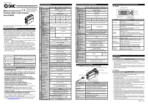
no evitarse, provocará la muerte o lesiones graves.Advertencia∙Comprueba siempre la conformidad con las leyes y reglamentos2 Especificaciones (continuación)3 Designación de las piezas3 Designación de las piezas (continuación)4 Instalación4.1 InstalaciónAdvertencia∙Lee detenidamente las normas de seguridad del productoentendiendo su contenido antes de realizar la instalación.∙Utiliza el producto dentro del rango de presión y temperatura detrabajo indicado.∙La presión de prueba podría variar en función de la temperatura delfluido. Comprueba los datos de las características para presión detrabajo y presión de prueba.4.2 EntornoAdvertencia∙Evita utilizar el producto en entornos donde esté expuesto a gasescorrosivos, productos químicos, agua salina o vapor.∙Evita los ambientes explosivos.∙No expongas el producto a la luz directa del sol. Utiliza una cubiertaprotectora adecuada.∙No instales el producto en zonas sometidas a vibraciones o impactossuperiores a los indicados en las características técnicas.∙Evita realizar el montaje del producto en lugares expuestos a calorradiante que provocará un aumento de la temperatura más allá delas características técnicas del producto.∙Consulta la dirección del caudal del fluido indicada en el productopara realizar la instalación y el conexionado.∙No montes el cuerpo con la parte inferior apuntando hacia arriba.La retención de aire puede hacer que no sea posible realizar unamedición precisa.∙No insertes cables metálicos u otros objetos extraños en la conexión.Puede dañar el sensor, provocando fallos o un funcionamiento defectuoso.∙No montes el producto en lugares que se utilizarán como punto de apoyo.El producto puede resultar dañado si se aplica una fuerza excesivasubiéndose encima de él.∙Si existe riesgo de que entren partículas extrañas en el fluido, instalay conecta un filtro o separador de neblina en el lado de entrada paraevitar fallos de funcionamiento.Podrían producirse daños en el producto o fallos de funcionamiento.El código del producto se muestra durante aproximadamente3 segundos tras la activación del suministro eléctrico.Se mostrará el modo de medición y se iniciará el funcionamiento.4.3 Montaje del panel∙ Inserta el adaptador de montaje en panel B (suministrado como accesorio) en la sección A del adaptador de montaje en panel.Empuja el adaptador para montaje en panel B desde la parte trasera hasta que el display quede fijado en el panel.El pasador de la fijación se engancha en la parte ranurada de la sección C del adaptador para panel para fijar el display.∙ El flujostato se puede montar en un panel con un grosor de 1 a 3.2 mm.4.4 Montaje con fijaciones∙ Monta la fijación usando los tornillos de montaje suministrados. ∙ El par de apriete requerido es 0.42 ±0.04 Nm.∙ Instala el producto (con fijación) usando los tornillos M3 (4 uds.) ∙ El grosor de la fijación es aprox. 1.2 mm4.5 ∙ Monta las piezas para montaje en raíl DIN usando los tornillos de montaje y tornillos de unión suministrados.∙ El par de apriete requerido de los tornillos de montaje en raíl DIN y los tornillos de unión es 0.4 ±0.05 Nm.∙ Consulta el manual de funcionamiento en el sitio web de SMC (URL: https:// ) para todas las dimensiones de montaje.4.6 ConexionadoPrecaución∙ Antes de realizar el conexionado, limpia cualquier rastro de virutas, aceite de corte, polvo, etc.∙ Comprueba que no haya fugas después de las tuberías.∙ Elimina el polvo del conexionado usando un soplador de aire antes de conectar el conexionado al producto.Podrían producirse daños en el producto o fallos de funcionamiento.4.7 CableadoPrecaución∙ No conectes ningún cable mientras la corriente esté activada. ∙ Comprueba que el cableado esté correctamente aislado.∙ No coloque los cables en la misma trayectoria que una línea de potencia o de alta tensión.En caso contrario, el producto puede sufrir un funcionamiento defectuoso debido a las interferencias por ruido y a los picos de tensión desde los cables de potencia y alta tensión hacia la línea de señal. ∙ El cableado debe ser tan corto como sea posible para evitar interferencias de ruido electromagnético y picos de tensión. No uses un cable con longitud superior a 30 m.∙ Asegúrate de que el terminal FG está conectado a tierra cuando utilices un regulador de conmutación comercial.∙ Si se usa la salida analógica, instala un filtro de ruido (filtro de línea, núcleo de ferrita, etc.) entre el suministro de alimentación para conmutación y este producto.Conexión/Desconexión∙ Cuando montes el conector, introdúcelo recto en el enchufe sujetando la palanca y el cuerpo del conector y empuja el conector hasta que la palanca enganche firmemente en la carcasa para bloquearlo.∙ Para desmontar el conector, presiona la palanca hacia abajo para soltar el gancho de la carcasa y extraiga el conector.Numeración de pins del conector (en el cable)Se suministra alimentación*: Las salidas continuarán funcionando durante el ajuste.*: Los ajustes del modo de ajuste sencillo y el modo de selección de función se reflejan unos en otros.6 Ajuste del caudal6.1 Operación de conmutaciónCuando el caudal exceda el punto de disparo, la salida del flujostato se activará. Cuando el caudal caiga por debajo del punto de disparo en la cantidad de histéresis o más, la salida se apagará.El valor de ajuste por defecto es el valor para activar el flujostato cuando el caudal está en el punto medio entre el límite inferior y el límite superior del rango de caudal nominal.Si esta condición mostrada resulta aceptable, mantén estos ajustes. *: Para la histéresis, consulta [F 1] Ajuste de OUT1 y [F 2] Ajuste de OUT2.[Modo de ajuste sencillo (modo de histéresis)]El modo de ajuste sencillo, el valor de ajuste y la histéresis se pueden modificar.(1) Pulsa el botón SET una vez en el modo de medición.Se mostrarán alternativamente [P_1] o [n_1] y el valor de ajuste de corriente.(2) Cambia el valor de ajuste usando el botón UP o DOWN y pulsa el botón SET para ajustar el valor. A continuación, el ajuste se mueve al ajuste de la histéresis (se puede usar la función instantánea). ∙ Mantén pulsado el botón UP para aumentar rápidamente el valor de ajuste.∙ Mantén pulsado el botón DOWN para disminuir rápidamente el valor de ajuste.(3) [H_1] y el valor de ajuste actual aparecerán alternativamente en el display.(4) Cambia el o DOWN ypulsa el botón SET. El ajuste se completa y el producto vuelve al modo de medición (Se puede usar la función instantánea).* En los modelos 2 salidas digitales para OUT1 y para OUT2, se mostrará [P_2] o [n_2]. Se ajustan simultáneamente.* Tras habilitar el ajuste pulsando el botón SET, es posible volver al modo de medición pulsando el botón SET durante al menos 2 segundos.* Si no se usa el modo de histéresis, se muestra «Valor de ajuste de entrada».* El valor de ajuste y la histéresis se limitan entre sí.* Para más detalles sobre los ajustes, vuelva a poner todas las funciones en el modo de selección de función.8 Ajuste de función8.1 Modo de selección de funciónEn el modo de medición, pulsa el botón SET durante 2 a 5 segundos para visualizar [F 0] en el display.Selecciona la función que se vaya a cambiar [F ].Pulsa el botón SET durante al menos 2 segundos en el modo de selección de función para volver al modo de medición. *: Algunos productos no disponen de todas las funciones. Si no hay ninguna función disponible o seleccionada debido a la configuración de otras funciones, se muestra [- - -] en el display secundario.Sin válvula de regulación de caudal (usando ZS-33-M) Con válvula de regulación de caudal (usando ZS-33-MS) C a u d a l8.2 Ajustes por defecto* El ajuste [Unidades] sólo es posible para modelos con función de selección de unidades.* La función [F 2] sólo está disponible para modelos con salidas digitales OUT1 y OUT2.* La función [F22] solo está disponible para modelos con salida analógica. Se puede seleccionar la función de intervalo analógico libre. ∙Función instantánea∙Función de bloqueo del teclado∙Función de puesta a ceroConsulta el manual de funcionamiento en el sitio web de SMC (URL:https://)10 Mantenimiento10.1 Mantenimiento generalPrecaución∙El incumplimiento de los procedimientos de mantenimientoapropiados podría causar un funcionamiento defectuoso delproducto, produciendo daños al equipo.∙El aire comprimido puede resultar peligroso si se maneja de manerainadecuada.∙El mantenimiento de los sistemas neumáticos debe realizarseúnicamente por personal cualificado.∙Antes de llevar a cabo el mantenimiento, corta el suministro eléctricoy la presión de alimentación. Comprueba que el aire se hadescargado a la atmósfera.∙Tras la instalación y el mantenimiento, conecta el suministro eléctricoy de presión al equipo y realiza pruebas de funcionamiento y defugas para comprobar que el equipo está correctamente instalado.∙Si alguna conexión eléctrica resulta afecta durante el mantenimiento,asegúrate de que vuelvan a conectarse correctamente y que se llevana cabo las comprobaciones de seguridad necesarias para garantizar laconformidad continuada con la reglamentación nacional aplicable.∙No realices ninguna modificación del producto.∙No desmontes el producto a menos que se indique en lasinstrucciones de instalación o mantenimiento.∙Cómo reiniciar el producto tras un corte de alimentación ocuando la alimentación se ha desconectado inesperadamenteSe mantendrán los ajustes existentes antes del corte de alimentacióno de la desactivación.También se recuperará el estado de salida existente antes del cortede alimentación o de la desactivación, aunque puede variar enfunción del entorno de trabajo.Por tanto, comprueba la seguridad de toda la instalación antes deutilizar de nuevo el producto.11 Forma de pedidoConsulta el catálogo/diagramas para la «Forma de pedido».12 Dimensiones externas (mm)Consulta las dimensiones externas el manual de funcionamiento en elsitio web de SMC (URL: ) .13.1 Indicación de errorSi el error no puede solucionarse después de tomar las medidasindicadas, o si se muestran errores distintos a los anteriores, ponte encontacto con SMC.Consulta el manual de funcionamiento en el sitio web de SMC (URL:https://) para obtener información detallada sobre laresolución de problemas.14.1 Garantía limitada y exención de responsabilidades/Requisitosde conformidadConsulta las «Precauciones en el manejo de productos SMC».15 ContactosConsulta la Declaración de Conformidad y URL: https://para los contactos.URL: (Global) http// (Europa)SMC Corporation, Akihabara UDX15F, 4-14-1, Sotokanda, Chiyoda-ku, Tokio 1010021 JAPÓNLas especificaciones pueden sufrir modificaciones sin previo aviso por parte delfabricante.© 2019 SMC Corporation Todos los derechos reservados.Plantilla DKP50047-F-085H。
羽毛球装备知识

KASON凯胜羽毛球拍介绍:1)凯胜Kason TSF 300Ti,08新款专业羽毛球拍(红色与金色两款,更多选择):2)凯胜Kason汤仙虎系列TSF Ti100专业羽毛球拍(国产青龙偃月刀)08新款!:3)凯胜/Kason 汤仙虎强弓系列 TSF 300A 羽毛球拍(挽弓当挽强):4) 凯胜/Kason 风云碳素系列 STREAM 8.3 羽毛球拍(金鳞岂是池中物):5) Kason凯胜K-MAX 2008羽毛球拍(新碳素系列)送线/3只装拍包,攻守均衡:6) Kason U4 羽毛球拍(拍子超轻,拍包巨漂亮):7) Kason U3 超轻系列羽毛球拍(轻盈的拍子,淡蓝色的漂亮拍包):8) Kason F1羽毛球拍(拍子轻盈速度快,拍包漂亮,适合女性选手):凯胜经典羽毛球拍分析及测评:KASON凯胜TSF100ti羽毛球拍:空拍价格大概在400元左右,这个价格段,应该有很多拍子,价格对于一般的羽毛球爱好者是最合适的了,例如RSL4900,RS3200等,都是这个价格段具有很大竞争力的,同样我觉得100TI是这个价格段的佼佼者。
相对与RSL4900,100TI价格会有一点优势,而且外观漆工KASON要比RSL好,杆我人觉得100TI要稍微硬点,拍头100TI也稍微轻点,不过KASON 的拉线磅数不如RSL有优势,RSL的拍子上30磅都蛮放心的,KASON的拍子质量不错,但是不敢上高磅,之前看过一个网友说可以上30磅,我都吓了一跳。
对于RS3200而言,价格就差不多了,不过3200的拍头要重点,属于暴力拍子了,拉线磅数方面也是可以上高磅的,据SKY所言,3200属于老7那类型,我也很同意。
但我觉得100TI的手感和挥拍的舒适度要比3200高。
100TI是款很经典的拍子,对于有一定水平的拉吊突击型的爱好者,的确是很好或者说是最好的选择,而且手感很好,打起来很舒服,如果是单双打都打的爱好者,我也推荐100TI,毕竟拍子很灵活,平抽挡很有优势,防守也不错。
西门子无线通讯

概述 — 可靠的工业无线移动通讯
应用领域
• 公共交通( 地铁、高架铁路、公共汽车); 产品具有高可靠性,适用于对温度和机械稳定性具有较高要求的应用场合。 由于采用了RCoax 电缆( 漏波电缆),可控制传输功率的辐射,因而提供了最 佳的无线电场。
SCALANCE W应用和解决方案
SCALANCE W应用和解决方案
• 循环发送的数据分组确保了严格实时和可靠的无线连接。由于冗余机制、 分组重发和现代编码机制确保了可靠和安全的数据传输,因此工业环 境内的干扰不会影响到无线连接。
• 在已建立的无线电场内,你可以使用MOBIC移动终端设备,从任何地 点在线访问最新的数据。
• 通过SNMP OPC服务器,可以把MS Office 应用程序方便地集成到解决 方案中。因而,该解决方案能够为通讯系统提供重要的通讯参数。
• AGV(Automatic Guided Vehicle),即自动导引车它是一种集声、光、电、计算机 为AG一V体作的为简活易动移装动配机平器台人)。。主要应主用要于应柔用性加工系统、柔性装配系统( 以
• AGVS是多辆AGV组成的完整系统。
SCALANCE W应用和解决方案 -AGV小车上的应用
SCALANCE W 工业无线移动通讯
概述 — 可靠的工业无线移动通讯 SCALANCE W应用和解决方案 SCALANCE W产品分类 网络结构介绍 组态IWLAN/PB实现PN IO通讯
概述 — 可靠的工业无线移动通讯
使用IEEE 802.11 标准并加以延伸,以符合工业领域用户 的要求,尤其是对确定性响应和冗余性有较高要求的用户。
SCALANCE W应用和解决方案 -立体仓库应用
RCOAX天馈线系统
• 红外线通讯的优点是通讯双方之间是 非接触的,无磨损故障现象,由于 红外线无法非直视通讯,当轨道发 生弯转时就无法通讯,而滑触线却 可以在轨道弯转处进行实时通讯。 RCOAX天馈线是这样一个综合了 两者的优点的馈线系统。
- 1、下载文档前请自行甄别文档内容的完整性,平台不提供额外的编辑、内容补充、找答案等附加服务。
- 2、"仅部分预览"的文档,不可在线预览部分如存在完整性等问题,可反馈申请退款(可完整预览的文档不适用该条件!)。
- 3、如文档侵犯您的权益,请联系客服反馈,我们会尽快为您处理(人工客服工作时间:9:00-18:30)。
MICRO-K microminiature circular connectors are rugged yet lightweight - and meet or exceed the applicable requirements of MIL-DTL-83513. Applications include biomedical,instrumentation and miniature black boxes.MIK:Accommodate up to 55 contacts on .050(1.27) centers (equivalent to 420 contacts per square inch). Five keyway polarization prevents cross plugging. The threaded coupling nuts provide strong, reliable coupling. MIK recepta-cles can be either front or back panel mounted;in back mounting applications, panel thickness of up to 3/32" can be used on the larger sizes.Maximum temperature range - 55˚C to + 125˚C.Standard MIK connectors are available in two shell sizes accommodating two contact arrangements pre-wired to your specific requirements.MIKM:Similar to our MIK, except has a steel shell and receptacle for improved ruggedness and RFI resistance. It accommodates up to 85twist pin contacts. Maximum temperature range - 55˚C to + 125˚ C.MIKQ:A quick disconnect metal shell and receptacle version that can be instantaneously disconnected yet provides a solid lock when engaged. Applications include commercial TV cameras, portableradios, military gun sights, airborne landing systems and medical equipment. Maximum temperature range - 55˚C to +125˚C.SpecificationsSTANDARD MATERIAL AND FINISHESELECTRO/MECHANICAL FEATURES*For plug onlyElectrodeposited for receptacle.MIKThermoplastic Stainless Steel Passivated Glass-reinforced Thermoplastic 50Microinch Gold Plated Copper AlloyStainless Steel Stainless Steel Passivated Glass-reinforced Thermoplastic 50Microinch Gold Plated Copper AlloyBrass Brass, Electroless Nickel Plated*Glass-reinforced Thermoplastic 50Microinch Gold Plated Copper AlloyNo. of Contacts Wire SizeContact Termination Contact Rating Couping Polarization Contact Spacing Shell Styles 7,55#24 AWG thru #32 AWGCrimp 3Amps Threaded Keyways .050 (1.27)Centers0-Wall Mtg.6-Straight Plug7,55, 85#24 AWG thru #32 AWGCrimp 3Amps Threaded Keyways .050 (1.27)Centers 0-Wall Mtg.6-Straight Plug7,19, 37#24 AWG thru #32 AWGCrimp 3Amps Push/Pull Keyways .050 (1.27)Centers 7-Jam Nut 6-Straight Plug 9-Rear Panel Mtg. ReceptacleShellCoupling Nut Insulator ContactsMIKM MIKQ MIKMIKMMIKQ How to OrderSERIESMIK M 6-55P** ** * *SERIESMIK: Microminiature Circular7, 19, 37, 55, 85(H) 001 -18", 7/34 strand, #26 AWG,MIL-W-16878/4, Type E Teflon,yellow.18",7/34 strand, #26 AWG,MIL-W-16878/4, Type E Teflon,color coded to MIL-STD-681System I.1/2" uninsulated solid #25AWG gold plated copper.1" uninsulated solid #25 AWG gold plated copper.(H) 003 -(L)1-(L)2-G -Cable nut and grip (MIKQ plug only)N -Nut only (MIKQ plug only)NOTE: Contact types cannot be interchanged between shell styles.P -Pin S -SocketH -Insulated round hook-up wire L -Uninsulated round solid wireNo Letter - Screw couping, plastic shell M -Screw coupling, metal shell Q -Push/Pull, metal shell 0-Wall mounting receptacle (MIK and MIKM only)6-Straight plug (MIK, MIKM and MIKQ)7-Jam nut mount (MIKQ only)9-Rear panel mounted receptacle (MIKQ)CONNECTOR TYPESSHELL STYLESCONNECTOR TYPE SHELL STYLECONTACT ARRANGEMENT CONTACT ARRANGEMENTS CONTACT TYPE CONTACT TYPE TERMINATION TYPETERMINATION TYPESTERMINATION LENGTH CODE TERMINATION LENGTH CODE (STANDARDS)HARDWAREHARDWARERoHS COMPLIANCE RStandard Wire Termination CodesThe following termination codes are listed for your information. For additional codes please refer to Appendix on page 79 and 81. All wire lengths are minimum.HARNESS TYPES (H)#26 A WG per MIL-W-16878Type E,Teflon S tranded L ength020019026029028001038009010011013017042027016034025002003023004005006048046041 3(76.2)6(152.4)8(203.2)10(254.0)12(304.8)18(457.2)20(508.0)24(609.6)30(762.0)36(914.4)48(1219.2)72(1828.8)120(3048.0)-All Yell o w Co l o r Cod e dContact ArrangementsFace View, Pin Side-(Male Twist Pin Contacts)MIK/MIKM/MIKQ7Contacts394857473831535512MIKQ19 ContactsMIKQ37 ContactsMIK/MIKM55 ContactsMIKM85 ContactsCavity identification numbers are for reference only, they do not appear on connectors.Shell Dimensions.335 (8.51)Max.MIK (Rear Panel Mount Thickness - see Tabulation "T")Weight given is 1/2" uninsulated, solid #25 AWG gold plated copper pigtailsPlu g Rece p tacleS hell S i z e7onl yRece p tacleS hell S i z e55 onl yPlu gPlugPart Numberby Shell SizeMIK6-7PMIK6-55PAThreadDMax.LMax.Avg. Weightoz. (gm.) ±5%5/16-24UNF-2B9/16-24UNF-2A.375 (9.52).755 (19.18).315 (8.00).460 (11.68).054 (1.54).202 (5.72)Part Numberby Shell SizeMIK0-7SMIK0-55SAThreadD±.010 (0.25)FMax.H±.003 (0.08)K±.010 (0.25)LMax.R±.005 (0.13)SMax.TMax.Avg. Weightoz. (gm.) ± 5% 5/16-24UNF-2B9/16-24UNF-2A.325 (8.26).625 (15.88).315 (8.00).440 (11.18).078 (1.98).089 (2.26).062 (1.57).100 (2.54).355 (9.02).495 (12.57).460 (11.68).580 (14.73).630 (16.00).760 (19.30).032 (0.81).062 (1.57).022 (.635).134 (3.81) ReceptacleShell Dimensions (Continued)MIKM (Rear Panel Mount Thickness .335 (8.51) max. - see Tabulation "T")D ..335 (8M a D.PlugReceptacleShell Size 7 onlyReceptacle Receptacle Shell Size 55 & 85PlugPlugMIKM6-7P 5/16-24UNF-2A.375(9.52) .315 (8.00) .054 (1.54)MIKM6-55P 5/8-24UNEF-2B.775(19.18) .440 (11.18) .333 (9.44) MIKM6-85P 11/16-24UNEF-2B .860 (21.84).460 (11.68).419 (11.88)MIKM0-7S 5/16-24UNF-2A .325 (8.26).320 (8.13) .078 (1.98) .062 (1.57) .400 (10.16) .460 (11.68).630 (16.00) .032 (0.81) .051 (1.45) MIKM0-55S 5/8-24UNEF-2A .625 (15.88).440 (11.18) .091 (2.31) .062 (1.57) .490 (12.45) .580 (14.73) .760 (19.30) .125 (3.18) .269 (7.62)MIKM0-85S 11/16-24UNEF-2A .745 (18.92) .440 (11.18).091 (2.31).062 (1.57).490 (12.45) .674 (17.12) .845 (21.46) .125 (3.18) .346 (9.80)Part Numberby Shell SizePart Number by Shell SizeA ThreadD Max.L Max.Avg. Weightoz. (gm.)+_5%A ThreadDF Max.H +_.003 (0.08)K L Max.R +_.005 (0.13)SMax.T Max.Avg. Weight oz. (gm.)+_5%MIKQ6-7S .385(9.78) .305 (7.75) .180 (4.57) .214 (6.08)MIKQ6-19S .515(13.08) .405 (10.29) .260 (6.60) .376 (10.70)MIKQ6-37S.760 (19.30).635 (16.13).350 (8.89).714 (20.23)MIKQ6-7S .510(12.95) .245 (6.22) .359 (9.12) 3/8-32UNEF-2A .128 (3.63)MIKQ7-37P.855(21.71).520 (13.20).740 (18.80)3/4-20UNEF-2A.300 (8.52)MIKQ (Front Panel Mounting Type Shown-.093 (2.36) Thickness)C .043±.005 C DIM.ACROSS FLA TPlugPlugReceptacle Receptacle*Std. Conn. not supplied with Cable Nut & Grip, See Mod Codes. Lanyard Relase Is Available. Consult factory.Part Number by Shell Size A MAX.B MAX.C Ref.Avg. Weight oz. (gm.)±5%Part Number by Shell Size A MAX.B MAX.C MAX.D Thread Avg. Weightoz. (gm.)±5%Front Panel Mounting-MIKQ7MIKQ Front Panel MountingMIKQ7-7P .364(9.24) .390 (9.91)MIKQ7-19P .475(12.06) .515 (13.08)MIKQ7-37P .740(18.78) .755 (19.17)Shell SizeA ±.005 (0.13)BDIA.Shell Dimensions (Continued)MIKQ9-7P (Back Panel Mounting)MIKQ9-19P (Back Panel Mounting)MIKQ9-37P (Back Panel Mounting)MIKQ Rear Panel MountingReceptacleReceptacleReceptacleRear Panel Mounting-MIKQ9Shell SizeMIKQ9-7PMIKQ9-19PMIKQ9-37P.425 (10.76).535 (13.58).740 (18.78).485 (12.32)MAX..250 ± .010WIREEXTENSIONLENGTH.250 ± .010 (6.35 ± 0.25).485 (12.32) MAX..440 (11.18).564 (14.33).755 (19.17)A±.005 (0.13)BDia.。