M7xA_SPI_3.3V_QS_DSV
CSM300(A)隔离SPI UART转CAN模块用户手册说明书

CSM300(A)隔离SPI / UART 转CAN 模块修订历史目录1. 功能简介 (1)1.1概述 (1)1.2产品特性 (1)1.3产品型号 (1)1.4应用场合 (1)2. 硬件说明 (2)2.1产品外观 (2)2.2引脚定义 (2)2.3IO说明 (3)2.4SPI转CAN硬件电路 (3)2.5UART转CAN硬件电路 (4)2.6外围保护电路 (5)2.7推荐组网方式 (7)3. 产品应用 (8)3.1名词解释 (8)3.2工作模式 (8)3.2.1SPI转CAN模式 (9)3.2.2UART转CAN模式 (13)3.2.3SPI配置模式 (13)3.2.4UART配置模式 (13)3.3数据转换方式 (13)3.3.1透明转换 (13)3.3.2透明带标识转换 (22)3.3.3自定义协议转换 (27)4. 产品配置 (33)4.1配置参数 (33)4.1.1转换参数 (33)4.1.2SPI参数 (33)4.1.3UART参数 (34)4.1.4CAN参数 (34)4.2出厂默认配置 (35)4.3配置通信协议 (36)4.3.1写配置参数 (36)4.3.2验证产品硬件标识 (39)4.3.3读配置参数 (40)4.4配置方式 (41)4.4.1MCU配置方式 (41)4.4.2上位机配置方式 (42)5. 辅助开发工具 (44)5.1CSM300CFG配置软件 (44)5.2CSM-Eval评估板 (45)5.3上位机配置实例 (46)6. 产品使用注意事项 (49)7. 免责声明 (50)CSM300(A)1.1 概述CSM300(A)系列隔离SPI / UART转CAN模块是集成微处理器、CAN收发器、DC-DC 隔离电源、信号隔离于一体的通信模块,当用户控制板上的CAN控制器资源不够时,可以通过SPI或UART接口扩展出更多的CAN总线接口。
该产品可以很方便地嵌入到具有SPI或UART接口的设备中,在不需改变原有硬件结构的前提下使设备获得CAN通讯接口,实现SPI设备或UART设备和CAN总线网络之间的数据通讯。
京微齐力M7 串口程序应用详解

通过 PC 端的串口助手,我们可以收到串口中断服务程序发送回来的数据,我们可以验证一下,数据是否一致。 串口助手收到的数据如下:
2.5 程序源码
2.5.1 Keil 部分的程序源码
#include <stdio.h> #include "cmem7_includes.h" #include "system_cmem7.h"
文件名称 cmem7_uart.c cmem7_uart.h
功能 UART 相关函数(驱动)程序文件 UART 相关函数的头文件
cmem7_uart_retarget.c
Printf 函数调用转换函数包含在这个文件里面
2.2 串口驱动使用方法:
1)定义 UART Type 变量 2)初始化 UART 端口 3)使能 UART 端口 // 发送数据 4)调用发送数据驱动(函数),发送数据。
备注: 不同的驱动库版本里面的该函数名称可能不同,比如有的版本里面该函数为 UART_Cmd
// 发送数据 // 由于我们已经引进了 文件,则可以直接调用 pintf 函数,进行串口的打印输出。
printf("\nSet ALL GPIO_OUT to High\n"); // 也可以通过 UART_Write 函数直接通过串口发送数据,如下:
// Enable UART INT UART_EnableInt(UART2, 0x020, TRUE); 然后编写串口中断服务程序 void UART2_IRQHandler(void) { unsigned char tmp; if(UART2->STATUS_b.RNE) {
tmp= (UART2->RX_BUF & 0x00FF); UART_Write(PRINT_UART,1,&tmp); } }
ncs8823_vga_ds V0.2

TEL:0755-8204 8740
FAX:0755-8293 3160
Page 3
6 Electrical Specifications
6.1 Operating Conditongs 6.2 Power Consumptoin 6.3 eDP Main Channel EIectrical Specification 6.4 Edp AUX channel EIectrical Specifications 6.5 Type-c Electrical Specification
Clock Refless clock system
Misc selectable I2C slave Firmware update through SPI,I2C,AUX interface Built-in video test pattern
Power 1.2V core supply 2.5V or 3.3V IO supply Power consumption ~ 150mA Deep-sleep mode power <1mW
FAX:0755-8293 3160
Page 2
5 Pin Description
No. 1 2 3 4 5 6 7 8 9 10 11 12 13 14 15 16 17 18 19 20 21 22 23 24 25 26 27 28 29 30 31 32 Thermal
Pin Name HSICP HSI0N HSI0P HSI1N HSI1P HSI2N HSI2P AUXRXP AUXRXN HSDVDD33 GB13 GB12 HPDOUT IOARP IOALP RES4P7K AVDD33 IOVBP IOVGP IOVRP VDACVDD33 OTPVDD25 SDAM SCLM HSYNC VSYNC RSTB SDAS SCLS DVDD12 DVDD33 HSICN GND
诺瓦科技LED显示屏接收卡A7s规格书

4.4.2 64 组串行数据接口.................................................................................................................................. 12 4.4.3 扩展功能参考设计 .................................................................................................................................. 15
子 4.3 指示灯 ......................................................................................................................................................... 8 电 4.4 数据接口定义(Top) ................................................................................................................................. 9 瓦 4.4.1 32 组并行数据接口.................................................................................................................................... 9
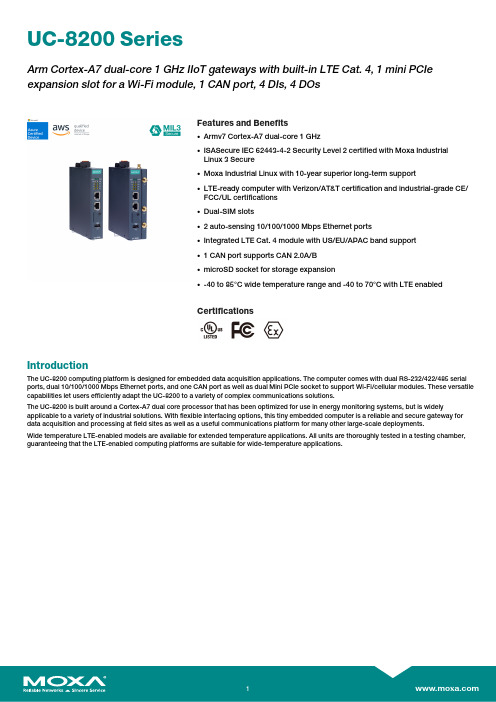
毛斯(Moxa)UC-8200系列双核ARM Cortex-A7 1GHz IIoT网关产品说明书

UC-8200SeriesArm Cortex-A7dual-core1GHz IIoT gateways with built-in LTE Cat.4,1mini PCIe expansion slot for a Wi-Fi module,1CAN port,4DIs,4DOsFeatures and Benefits•Armv7Cortex-A7dual-core1GHz•ISASecure IEC62443-4-2Security Level2certified with Moxa IndustrialLinux3Secure•Moxa Industrial Linux with10-year superior long-term support•LTE-ready computer with Verizon/AT&T certification and industrial-grade CE/FCC/UL certifications•Dual-SIM slots•2auto-sensing10/100/1000Mbps Ethernet ports•Integrated LTE Cat.4module with US/EU/APAC band support•1CAN port supports CAN2.0A/B•microSD socket for storage expansion•-40to85°C wide temperature range and-40to70°C with LTE enabledCertificationsIntroductionThe UC-8200computing platform is designed for embedded data acquisition applications.The computer comes with dual RS-232/422/485serial ports,dual10/100/1000Mbps Ethernet ports,and one CAN port as well as dual Mini PCIe socket to support Wi-Fi/cellular modules.These versatile capabilities let users efficiently adapt the UC-8200to a variety of complex communications solutions.The UC-8200is built around a Cortex-A7dual core processor that has been optimized for use in energy monitoring systems,but is widely applicable to a variety of industrial solutions.With flexible interfacing options,this tiny embedded computer is a reliable and secure gateway for data acquisition and processing at field sites as well as a useful communications platform for many other large-scale deployments.Wide temperature LTE-enabled models are available for extended temperature applications.All units are thoroughly tested in a testing chamber, guaranteeing that the LTE-enabled computing platforms are suitable for wide-temperature applications.AppearanceUC-8210UC-8220SpecificationsComputerCPU Armv7Cortex-A7dual-core1GHzDRAM2GB DDR3LSupported OS Moxa Industrial Linux1(Debian9,kernel4.4),2027EOLMoxa Industrial Linux31(Debian11,kernel5.10),2031EOLSee /MILStorage Pre-installed8GB eMMCExpansion Slots MicroSD(SD3.0)socket x13OS is selectable via Moxa Computer Configuration System(CCS)for CTO models.For the model names,see the Ordering Information section of thedatasheet PDF file.Computer InterfaceEthernet Ports Auto-sensing10/100/1000Mbps ports(RJ45connector)x2 Serial Ports RS-232/422/485ports x2,software selectable(DB9male) CAN Ports CAN2.0A/B x1(DB9male)Digital Input DIs x4Digital Output DOs x4USB2.0USB2.0hosts x1,type-A connectorsWi-Fi Antenna Connector UC-8220Models:RP-SMA x2Cellular Antenna Connector UC-8220Models:SMA x2GPS Antenna Connector UC-8220Models:SMA x1Expansion Slots UC-8220-T-LX:mPCIe slot x2UC-8220-T-LX US/EU/AP Models:mPCIe slot x1SIM Format UC-8220Models:NanoNumber of SIMs UC-8220Models:2Buttons Programmable buttonTPM TPM v2.0Ethernet InterfaceMagnetic Isolation Protection 1.5kV(built-in)Security FunctionsHardware-based Security TPM2.0Hardware Root of Trust Secure BootIntrusion Detection Host-based Intrusion DetectionSecurity Tools Security Diagnostic ToolSecurity Event AuditingSecure UpdateDisk Protection LUKS Disk EncryptionRecovery One-step recovery to the last known secure stateDual-system design with automatic failbackReliability Network Keep AliveNetwork Failover and FailbackSerial InterfaceBaudrate300bps to921.6kbpsData Bits7,8Stop Bits1,2Parity None,Even,Odd,Space,MarkFlow Control RTS/CTS,XON/XOFFADDC(automatic data direction control)for RS-485RTS Toggle(RS-232only)Console Port1x4-pin header to DB9console portRS-232TxD,RxD,RTS,CTS,DTR,DSR,DCD,GNDRS-422Tx+,Tx-,Rx+,Rx-,GNDRS-485-2w Data+,Data-,GNDCAN InterfaceNo.of Ports1Connector DB9maleBaudrate10to1000kbpsIndustrial Protocols CAN2.0ACAN2.0BIsolation2kV(built-in)Signals CAN_H,CAN_L,CAN_GND,CAN_SHLD,CAN_V+,GNDDigital InputsConnector Screw-fastened Euroblock terminalDry Contact Off:openOn:short to GNDIsolation3K VDCSensor Type Wet contact(NPN)Dry contactWet Contact(DI to COM)On:10to30VDCOff:0to3VDCDigital OutputsConnector Screw-fastened Euroblock terminalCurrent Rating200mA per channelI/O Type SinkVoltage24VDC nominal,open collector to30VDCCellular InterfaceCellular Standards LTE Cat.4Band Options US Models:LTE Band2(1900MHz)/LTE Band4(1700MHz)/LTE Band5(850MHz)/LTE Band13(700MHz)/LTE Band17(700MHz)UMTS/HSPA850MHz/1900MHzCarrier Approval:Verizon,AT&TEU Models:LTE Band1(2100MHz)/LTE Band3(1800MHz)/LTE Band5(850MHz)/LTE Band7(2600MHz)/LTE Band8(900MHz)/LTE Band20(800MHz)UMTS/HSPA850MHz/900MHz/1900MHz/2100MHzAP Models:LTE Band1(2100MHz)/LTE Band3(1800MHz)/LTE Band5(850MHz)/LTE Band7(2600MHz)/LTE Band8(900MHz)/LTE Band28(700MHz)UMTS/HSPA850MHz/900MHz/1900MHz/2100MHzReceiver Types GPS/GLONASS/GalileoState-of-the-art GNSS solutionAccuracy Position:2.0m@CEP50Acquisition Hot starts:1.1secCold starts:29.94secSensitivity Cold starts:-145dBmTracking:-160dBmTime Pulse0.25Hz to10MHzLED IndicatorsSystem Power x2Programmable x1SIM card indicator x1Wireless Signal Strength Cellular/Wi-Fi x6Power ParametersNo.of Power Inputs Redundant dual inputsInput Voltage12to48VDCPower Consumption10WInput Current0.8A@12VDCReliabilityAlert Tools External RTC(real-time clock)Automatic Reboot Trigger External WDT(watchdog timer)Physical CharacteristicsDimensions UC-8220Models:141.5x120x39mm(5.7x4.72x1.54in)UC-8210Models:141.5x120x27mm(5.7x4.72x1.06in)141.5x120x27mm(5.7x4.72x1.06in)Weight UC-8210Models:560g(1.23lb)UC-8220Models:750g(1.65lb)Housing SECCMetalIP Rating IP30Installation DIN-rail mountingWall mounting(with optional kit)Environmental LimitsOperating Temperature-40to70°C(-40to158°F)Storage Temperature(package included)-40to85°C(-40to185°F)Ambient Relative Humidity5to95%(non-condensing)Shock IEC60068-2-27Vibration2Grms@IEC60068-2-64,random wave,5-500Hz,1hr per axis(without USB devicesattached)Standards and CertificationsEMC EN55032/35EN61000-6-2/-6-4EMI CISPR32,FCC Part15B Class AEMS IEC61000-4-2ESD:Contact:4kV;Air:8kVIEC61000-4-3RS:80MHz to1GHz:10V/mIEC61000-4-4EFT:Power:2kV;Signal:1kVIEC61000-4-6CS:10VIEC61000-4-8PFMFIEC61000-4-5Surge:Power:0.5kV;Signal:1kV Industrial Cybersecurity IEC62443-4-1IEC62443-4-2Hazardous Locations Class I Division2ATEXIECExCarrier Approvals VerizonAT&TSafety UL62368-1EN62368-1Green Product RoHS,CRoHS,WEEEMTBFTime UC-8210-T-LX-S:708,581hrsUC-8220-T-LX:650,836hrsUC-8220-T-LX-US-S/EU-S/AP-S:528,574hrs Standards Telcordia(Bellcore)Standard TR/SRWarrantyWarranty Period5yearsDetails See /warrantyPackage ContentsDevice1x UC-8200Series computerDocumentation1x quick installation guide1x warranty cardInstallation Kit1x DIN-rail kit(preinstalled)1x power jack6x M2.5mounting screws for the cellular module Cable1x console cableDimensions UC-8210UC-8220Ordering Information12UC-8210-T-LX-SDefault:MIL1(-Debian9),2027EOLOrder WithModel UC-8210-T-LX-S(CTO):MIL3(Debian11)Secure/Standard,2031EOLWith MIL3Secure1GHzDual CoreBuilt in––-40to85°CUC-8220-T-LXDefault:MIL1(-Debian9),2027EOLOrder WithModel UC-8220-T-LX(CTO):MIL3(Debian11)Secure/Standard,2031EOLWith MIL3Secure1GHzDual CoreBuilt in Reserved Reserved-40to70°CUC-8220-T-LX-US-SDefault:MIL1(-Debian9),2027EOLOrder WithModel UC-8220-T-LX-US-S(CTO):MIL3(Debian11)Secure/Standard,2031EOLWith MIL3Secure1GHzDual CoreBuilt inUS region LTEmodulepreinstalledReserved-40to70°CUC-8220-T-LX-EU-SDefault:MIL1(-Debian9),2027EOLOrder WithModel UC-8220-T-LX-EU-S(CTO):MIL3(Debian11)Secure/Standard,2031EOLWith MIL3Secure1GHzDual CoreBuilt inEurope regionLTE modulepreinstalledReserved-40to70°CUC-8220-T-LX-AP-SDefault:MIL1(-Debian9),2027EOLOrder WithModel UC-8220-T-LX-AP-S(CTO):MIL3(Debian11)Secure/Standard,2031EOLWith MIL3Secure1GHzDual CoreBuilt inAPAC regionLTE modulepreinstalledReserved-40to70°CUC-8210-T-LX-S(CTO)MIL3(Debian11)Secure orStandard,2031EOLWith MIL3Secure1GHzDual CoreBuilt in––-40to85°CUC-8220-T-LX(CTO)MIL3(Debian11)Secure orStandard,2031EOLWith MIL3Secure1GHzDual Core–Reserved Reserved-40to70°CUC-8220-T-LX-US-S (CTO)MIL3(Debian11)Secure orStandard,2031EOLWith MIL3Secure1GHzDual CoreBuilt inUS region LTEmodulepreinstalledReserved-40to70°C12UC-8220-T-LX-EU-S (CTO)MIL3(Debian11)Secure orStandard,2031EOLWith MIL3Secure1GHzDual CoreBuilt inEurope regionLTE modulepreinstalledReserved-40to70°CUC-8220-T-LX-AP-S (CTO)MIL3(Debian11)Secure orStandard,2031EOLWith MIL3Secure1GHzDual CoreBuilt inAPAC regionLTE modulepreinstalledReserved-40to70°CAccessories(sold separately)Power AdaptersPWR-12150-EU-SA-T Locking barrel plug,12VDC,1.5A,100to240VAC,EU plug,-40to75°C operating temperature PWR-12150-UK-SA-T Locking barrel plug,12VDC,1.5A,100to240VAC,UK plug,-40to75°C operating temperature PWR-12150-USJP-SA-T Locking barrel plug,12VDC1.5A,100to240VAC,US/JP plug,-40to75°C operating temperature PWR-12150-AU-SA-T Locking barrel plug,12VDC,1.5A,100to240VAC,AU plug,-40to75°C operating temperature PWR-12150-CN-SA-T Locking barrel plug,12VDC,1.5A,100to240VAC,CN plug,-40to75°C operating temperature Power WiringCBL-PJTB-10Non-locking barrel plug to bare-wire cableCablesCBL-F9DPF1x4-BK-100Console cable with4-pin connector,1mWi-Fi Wireless ModulesUC-8200-WLAN22-AC Wireless package for UC-8200V2.0or later with Wi-Fi module,2screws,2spacers,1heat sink,1pad AntennasANT-LTEUS-ASM-01GSM/GPRS/EDGE/UMTS/HSPA/LTE,1dBi,omnidirectional rubber-duck antennaANT-LTE-ASM-04BK704to960/1710to2620MHz,LTE omnidirectional stick antenna,4.5dBiANT-LTE-OSM-03-3m BK700-2700MHz,multiband antenna,specifically designed for2G,3G,and4G applications,3m cable ANT-LTE-ASM-05BK704-960/1710-2620MHz,LTE stick antenna,5dBiANT-LTE-OSM-06-3m BK MIMO Multiband antenna with screw-fastened mounting option for700-2700/2400-2500/5150-5850MHzfrequenciesANT-WDB-ARM-02022dBi at2.4GHz or2dBi at5GHz,RP-SMA(male),dual-band,omnidirectional antennaDIN-Rail Mounting KitsUC-8210DIN-rail Mounting Kit DIN-rail mounting kit for UC-8210with4M3screwsUC-8220DIN-rail Mounting Kit DIN-rail mounting kit for UC-8220with4M3screwsWall-Mounting KitsUC-8200Wall-mounting Kit Wall-mounting kit for UC-8200with4M3screws©Moxa Inc.All rights reserved.Updated Jul18,2023.This document and any portion thereof may not be reproduced or used in any manner whatsoever without the express written permission of Moxa Inc.Product specifications subject to change without notice.Visit our website for the most up-to-date product information.。
综合检测单元 SCM7 使用说明书

深圳市硕亚科技有限公司综合检测单元SCM7-使用说明书版本号1.0 2019年04月10日1、概述综合检测单元是对系统交、直流检测及对整流模块进行控制的一种设备。
内部使用CPU控制,采取标准MODBUS 通信协议,主要用于测量三相交流电压、直流电压、直流电流、开关量输入检测、继电器输出控制和直流绝缘检测。
可根据要求设计不同的通讯协议2、使用方法2.1 安装尺寸和模块示意图。
绝缘检测单元模块为板后安装,安装尺寸见图一;外形示意见图二图一 安装尺寸图二 外形示意图 2.2 面板示意图:2.3 端口定义:端口 引脚 标号 定义 备注开关量输入端口 1 S1 1#开关量输入2 S2 2#开关量输入3 S3 3#开关量输入4 S4 4#开关量输入5 S5 5#开关量输入6 S6 6#开关量输入7 S7 7#开关量输入8 S8 8#开关量输入9 S9 9#开关量输入10 S10 10#开关量输入11 S11 11#开关量输入12 S12 12#开关量输入13 S13 13#开关量输入14 S14 14#开关量输入15 S15 15#开关量输入16 S16 16#开关量输入17 S17 17#开关量输入18 S18 18#开关量输入19 S19 19#开关量输入20 S20 20#开关量输入21 S21 21#开关量输入22 S22 22#开关量输入23 S23 23#开关量输入24 S24 24#开关量输入25 COM 公共端开关量输入公共端 26 COM 公共端开关量输出端口 28 K1_COM1#继电器输出容量AC250V/5A,DC30V/5A29 K1_OUT30 K2_COM2#继电器输出31 K2_OUT32 K3_COM3#继电器输出33 K3_OUT34 K4_COM4#继电器输出35 K4_OUT36 K5_COM5#继电器输出37 K5_OUT38 K6_COM6#继电器输出39 K6_OUT40 K7_COM7#继电器输出41 K7_OUT 42 K8_COM 8#继电器输出43K8_OUT 交流一路44 A1(L1)交流一路A 相电压 测量范围:0~500VAC304~456VAC 范围内测量误差≤±1.0%45 B1(N1)交流一路B 相电压 46 C1 交流一路C 相电压 交流二路47 A2(L2)交流二路A 相电压 48 B2(N2)交流二路B 相电压 49 C2 交流二路C 相电压 控母电压 50+ 控母电压正 测量范围:0~300VDC;90%~130%额定电压范围内测量误差≤±0.5%51 - 控母电压负 52 ETH 大地 合母电压 53 + 合母电压正 54 - 合母电压负 电池电压55 + 电池电压正 56 - 电池电压负 控母电流57+ +12V 测量范围:0~100A 20%~100%量程内测量误差≤±1%58 - -12V59 I 控母电流采样信号 60 G GND 温度测量61+ +5V测量范围:-10℃~+100℃测量误差≤±3℃ 62 T 温度探头信号 63 G GND 电池电流64+ +12V 测量范围:0~±100A 20%~100%量程内测量误差≤±1% 65 - -12V66 I 电池电流采样信号 67 G GND 功能68D1 第一位 备用 69 D2 第二位 备用 70 D3 第三位 备用 71 D4 第四位 备用RS48572B D-/B RS485通讯端口 用于与上位机通讯端口73 A D+/A 74 B D-/B 75A D+/A 输入电源76 + 直流正(AC2) 工作电源输入DC 80V-300V(AC110V- 220V77 -直流负(AC1) 复位 复位键重新启动程序告警 故障告警指示灯 发生系统报警时故障灯常亮,解除后自动消失状态程序运行状态指示灯常亮:检测桥等待中闪烁:程序正常运行熄灭:程序不运行2.4 电流传感器接线方式:SCM7采用闭环型霍尔电流传感器进行电流采样,闭环型霍尔电流传感器具有良好的线性度及精度,低漂移,响应时间快、频带宽,原、副边之间高度绝缘。
杭州瑞盟科技有限公司MS90C104 30bit平板显示器LVDS信号接收器说明书

2013.08.12
共9页 第6页
图 4.锁相环设置时间
MS90C104
图 5.接收器状态
Vdiff=(RxIN+)-(RxIN-),……(RxCLKIN+)-(RxCLKIN-)
图 6.并行 TTL 输出数据与 LVDS 输入数据匹配关系
Previous Cycle
Next Cycle
RCLK RL4
1.4W
电学特性
符号 VIH VIL VOH
VOL
IIN IOS
参数 输入高电平 输入低电平 输出高电平
输出低电平
输入电流 输出短路电流
条件
Min
2.0
GND
IOH = -4mA(data) 2.4 IOH = -8mA(clock) IOL = 4mA(data) IOL = 8mA(clock)
-3-
版本号:1.2
2013.08.12
共9页 第3页
MS90C104
推荐工作条件
电源电压(VCC) CMOS/TTL 输入电压 CMOS/TTL 输出电压 LVDS 接收输入电压 结点温度 温度范围 瞬间耐温(焊接,4 秒) 最大功耗(25℃) MS90C104
-0.3V - 4.0V -0.3V - (VCC+0.3V) -0.3V - (VCC+0.3V) -0.3V - (VCC+0.3V) +150℃ -40℃ - 100℃ +260℃
RX0/7/14/21/28
RX1/8/15/22/29
RX2/9/16/23/30 RX3/10/17/24/31 RX4/11/18/25/32 RX5/12/19/26/33 RX6/13/20/27/34
TMS570LS介绍

展品大类:TMS570LS ARM Cortex -R4F系列开发工具和软件∙rated by 0 users∙此帖子有2 回复|∙ 3 Followers作者iSupport发表于2012-5-20 22:15o rated by 0 userso TMS570LS ARM Cortex -R4F系列开发工具和软件oTMS570LS ARM® Cortex TM-R4F 微处理器工具和软件TI 及其合作伙伴推出专为加速并简化开发过程而设计的各种Hercules TMS570LS 微处理器开发工具和软件。
每个开发套件均附带文档、硬件原理图和代码示例。
Hercules TMS570LS 工具和软件结合了IDE、RTOS、外设驱动程序及其他实用程序,为开始评估器件并过渡到应用开发提供了有效方式。
o开发套件o IDEo RTOSo通信驱动器o建模和校准o仿真器o更多工具和软件开发套件套件器件型号描述价格TMS570LS31x Hercules 开发套件TMDX570LS31HDKTMS570LS31x Hercules 开发套件是Hercules安全微处理器平台开发入门的理想选择。
该套件中包括一个开发板、DC 电源、一根迷你B 型USB 电缆,一根以太网电缆以及一张软件安装DVD,其中包括Code Composer Studio IDE、HALCoGen、nowFlash、HET IDE、演示软件及代码示例。
该开发板包含一个板载XDS100v2JTAG 仿真器,可以访问MCU 的通信接口以及所有外设引脚。
立即订购199.00美元TMS570LS31x USB 记忆棒TMDX570LS31USBTMS570LS31x Hercules USB 开发记忆棒是评估Hercules 安全微处理器平台的理想选择。
USB 记忆棒具有集成XDS100v2 JTAG 仿真立即订购器,可访问多个关键外设引脚且完全由PC 的USB 端口供电。
- 1、下载文档前请自行甄别文档内容的完整性,平台不提供额外的编辑、内容补充、找答案等附加服务。
- 2、"仅部分预览"的文档,不可在线预览部分如存在完整性等问题,可反馈申请退款(可完整预览的文档不适用该条件!)。
- 3、如文档侵犯您的权益,请联系客服反馈,我们会尽快为您处理(人工客服工作时间:9:00-18:30)。
M7xA 3.3V Serial Flash NAND Memory Device number:MT29F2G01ABAGDSF, MT29F2G01ABAGD12,
MT29F2G01ABAGDWB, MT29F1G01ABAFDSF,
MT29F1G01ABAFD12, MT29F1G01ABAFDWB Device type:2Gb and 1Gb 3.3V SPI NAND
Internal Micron Designation: A4
Data sheet revision: C
Important Information
The samples referenced by this Data Sheet Variance (DSV), have a pre-production sample status. Products with this status may be labeled as Engineering Samples (ES) or Qualification Samples (QS). This designation means that the product design, test, and characterization is not complete. The performance of pre-qualification samples may deviate materially from the product specifications contained in the device data sheet. The DSV documents known deviations with the product. Throughout the development process, Micron Technology, Inc.®periodically updates the DSV as new information becomes available. These updates are available from your local representative.
Pre-production samples are provided to select customers for evaluation and application development. Before using the samples in an application, the DSV should be carefully reviewed with a Micron representative. Micron also requests feedback on the performance of the samples in the target application. The test flow of pre-production samples may differ substantially from that used by Micron®production-status devices. These differences may include decreased margin in voltage, temperature or timing specifications, omission of device stress tests, incomplete analysis of key parameters, and incomplete fault coverage. The quality and reliability of these samples may not be representative of the final product. Under no circumstances should they be used for any reliability testing without a written waiver from Micron. The customer acknowledges that pre-production samples may deviate from the corresponding data sheet and may bear defects due to their development status. Although the DSV endeavors to fully document these deviations, it is not represented as complete or final. Micron Technology Inc. rejects any product warranty for pre-production samples and waives any liability for consequential and incidental damages through their use in any application.
27-Apr-16 1 Micron Confidential M7xA 3.3V SPI NAND © 2016 Micron Technology, Inc. All Rights Reserved
M7xA 3.3V Serial Flash NAND Memory Device Deviations
Parameter Verified Limit Spec Limit Remark
Standby current
160uA 50uA CE# = VCC; VIN = VSS or VCC
I SB2
27-Apr-16 2 Micron Confidential M7xA 3.3V SPI NAND © 2016 Micron Technology, Inc. All Rights Reserved。
