STPS1H100A
灵活溅水管带配件(HD-SP-01AS、HD-SP-01A、HD-SP-02AS、HD-SP-02A

VENF.EX15902 - Flexible Sprinkler Hose with FittingsFlexible Sprinkler Hose with FittingsModelRated Pressure,psig Max Ambient Temp, °F Nom Inlet by Outlet Size, in.Assembly Length,ft (mm)Max No. of 90° Bends Min Bend Radius, in.Equivalent Length of 1 in.Schedule 40Steel Pipe (C = 120), ft Flexibility Type HD-SP-01AS unbraided 1752251x1/2 2.3 (700)2418Limited HD-SP-01A unbraided 1752251x1/2 2.6 (780)2427Limited HD-SP-02AS unbraided 1752251x1/2 3.3 (1000)3444Limited HD-SP-02A unbraided 1752251x1/2 4.0 (1220)3453Limited HD-SP-03A unbraided 1752251x1/2 5.1 (1540)3468Limited HD-SP-04A unbraided 1752251x1/2 6.0 (1830)3473Limited HD-SP-01BS unbraided 1752251x3/4 2.3 (700)2432Limited HD-SP-01B unbraided 1752251x3/4 2.6 (780)2433Limited HD-SP-02BS unbraided 1752251x3/4 3.3 (1000)3448Limited HD-SP-02B unbraided 1752251x3/4 4.0 (1220)3455Limited HD-SP-03B unbraided 1752251x3/4 5.1 (1540)3463Limited HD-SP-04B unbraided 1752251x3/4 6.0 (1830)3476Limited HD-SPN-01AS unbraided 1752251x1/2 2.3 (700)2424Limited HD-SPN-01A unbraided 1752251x1/2 2.6 (780)2430Limited HD-SPN-02AS unbraided 1752251x1/2 3.3 (1000)3446Limited HD-SPN-02A unbraided 1752251x1/2 4.0 (1220)3453Limited HD-SPN-03A unbraided 1752251x1/2 5.1 (1540)3470Limited HD-SPN-04A unbraided 1752251x1/2 6.0 (1830)3484Limited HD-UB-700 unbraided 200225 1 X 1/2 2.3 (700)2432Limited HD-UB-1000 unbraided 200225 1 X 1/2 3.3 (1000)3455Limited HD-UB-1200 unbraided 200225 1 X 1/2 3.9 (1200)3464Limited HD-UB-1500 unbraided2002251 X 1/24.9 (1500)3475LimitedHD FIRE PROTECT PVT LTD D-6/2, Road No. 34Wagle Industrial EstateThane, Maharashtra 400604 IndiaEX15902HD-UB-1800 unbraided200225 1 X 1/2 5.9 (1800)3481Limited HD-UB-700 unbraided200225 1 X 3/4 2.3 (700)2431Limited HD-UB-1000 unbraided200225 1 X 3/4 3.3 (1000)3450Limited HD-UB-1200 unbraided200225 1 X 3/4 3.9 (1200)3457Limited HD-UB-1500 unbraided200225 1 X 3/4 4.9 (1500)3468Limited HD-UB-1800 unbraided200225 1 X 3/4 5.9 (1800)3479LimitedModelRatedPressure,psigMaxAmbientTemp, °FNom Inletby OutletSize, in.AssemblyLength,ft (mm)MaxNo. of90° BendsMin BendRadius, in.EquivalentLength of1 in.Schedule 40Steel Pipe(C = 120), ftFlexibilityTypeHD-N25-700 unbraided2003001x1/2 2.3 (700)2322Limited HD-N25-1000 unbraided2003001x1/2 3.3 (1000)3339Limited HD-N25-1200 unbraided2003001x1/2 3.9 (1200)3356Limited HD-N25-1500 unbraided2003001x1/2 4.9 (1500)3359Limited HD-N25-1800 unbraided2003001x1/2 5.9 (1800)3367Limited HD-B25-700 braided2003001x1/2 2.3 (700)2322Limited HD-B25-1000 braided2003001x1/2 3.3 (1000)3339Limited HD-B25-1200 braided2003001x1/2 3.9 (1200)3356Limited HD-B25-1500 braided2003001x1/2 4.9 (1500)3359Limited HD-B25-1800 braided2003001x1/2 5.9 (1800)3367Limited HD-B25S-700 braided2003001x1/2 2.3(700)2324Limited HD-B25S-1000 braided2003001x1/2 3.3 (1000)3344Limited HD-B25S-1200 braided2003001x1/2 3.9 (1200)3363Limited HD-B25S-1500 braided2003001x1/2 4.9 (1500)3376Limited HD-B25S-1800 braided2003001x1/2 5.9 (1800)3378Limited HD-B28-700 braided2002251x1/2 2.3 (700)2314Limited HD-B28-1000 braided2002251x1/2 3.3 (1000)3327Limited HD-B28-1200 braided2002251x1/2 3.9 (1200)3331Limited HD-B28-1500 braided2002251x1/2 4.9 (1500)3343Limited HD-B28-1800 braided2002251x1/2 5.9 (1800)3349Limited HD-N25-700 unbraided2003001x3/4 2.3 (700)2328Limited HD-N25-1000 unbraided2003001x3/4 3.3 (1000)3354Limited HD-N25-1200 unbraided2003001x3/4 3.9 (1200)3363LimitedHD-N25-1500 unbraided2003001x3/4 4.9 (1500)3374Limited HD-N25-1800 unbraided2003001x3/4 5.9 (1800)3374Limited HD-B25-700 braided2003001x3/4 2.3 (700)2328Limited HD-B25-1000 braided2003001x3/4 3.3 (1000)3354Limited HD-B25-1200 braided2003001x3/4 3.9 (1200)3363Limited HD-B25-1500 braided2003001x3/4 4.9 (1500)3374Limited HD-B25-1800 braided2003001x3/4 5.9 (1800)3374Limited HD-B25S-700 braided2003001x3/4 2.3 (700)2329Limited HD-B25S-1000 braided2003001x3/4 3.3 (1000)3354Limited HD-B25S-1200 braided2003001x3/4 3.9 (1200)3355Limited HD-B25S-1500 braided2003001x3/4 4.9 (1500)3370Limited HD-B25S-1800 braided2003001x3/4 5.9 (1800)3392Limited HD-B28-700 braided2002251x3/4 2.3 (700)2318Limited HD-B28-1000 braided2002251x3/4 3.3 (1000)3335Limited HD-B28-1200 braided2002251x3/4 3.9 (1200)3341Limited HD-B28-1500 braided2002251x3/4 4.9 (1500)3342Limited HD-B28-1800 braided2002251x3/4 5.9 (1800)3343Limited HD-B-6 Braided1752251x1/2 2.0 (610)17.512Limited HD-B-12 Braided1752251x1/2 4.0 (1220)37.529Limited HD-B-15 Braided1752251x1/2 5.0 (1525)37.568Limited HD-B-18 Braided1752251x1/2 5.9 (1800)37.594Limited HD-B-6 Braided1752251x3/4 2.0 (610)17.521Limited HD-B-12 Braided1752251x3/4 4.0 (1220)37.536Limited HD-B-15 Braided1752251x3/4 5.0 (1525)37.573Limited HD-B-18 Braided1752251x3/4 5.9 (1800)37.599LimitedModelRatedPressure,psigMaxAmbientTemp, °FNom Inletby OutletSize, in.AssemblyLength,ft (mm)MaxNo. of90° BendsMin BendRadius, in.EquivalentLength of1 in.Schedule 40Steel Pipe(C = 120), ftFlexibilityTypeHD-28B-700 braided2002251x1/2 2.3 (700)3318Limited HD-28B-1000 braided2002251x1/2 3.3 (1000)5323Limited HD-28B-1200 braided2002251x1/2 3.9 (1200)7329LimitedHD-28B-1500 braided2002251x1/2 4.9 (1500)9339Limited HD-28B-1800 braided2002251x1/2 5.9 (1800)12350Limited HD-28B-700 braided2002251x3/4 2.3 (700)3320Limited HD-28B-1000 braided2002251x3/4 3.3 (1000)5324Limited HD-28B-1200 braided2002251x3/4 3.9 (1200)7331Limited HD-28B-1500 braided2002251x3/4 4.9 (1500)9340Limited HD-28B-1800 braided2002251x3/4 5.9 (1800)12370LimitedThe model HD-N25 series, HD-B25 series, HD-B25S series and HD-B28 series flexible sprinkler hose with fittings are intended to be installed with the RB-BT-UL-1 and RB-F-58T bracket combination in accordance with the manufacturer's installation instructions dated 21th of December, 2018.The model HD-N25 series and HD-B25S series flexible sprinkler hose with fittings are intended to be installed with the SprinkFlex SFO24BKT1 orSFO48BKT1 bracket combinations in accordance with the manufacturer's installation instructions dated 21th of December, 2018.The model HD-N25 series, HD-B25 series, HD-B25S series and HD-B28 series flexible sprinkler hose with fittings are intended to be installed with the RB-BT-UL-2 and RB-F-58T bracket combination in accordance with the manufacturer's installation instructions dated 21th of December, 2018.The Model HD-SP flexible sprinkler hose with fittings are intended to be installed with the B-13 and A-10 bracket combination in accordance with the manufacturer's installation instructions dated March 4, 2009.The Model HD-SPN flexible sprinkler hose with fittings are intended to be installed with the B-7 end bracket and A-4 center bracket combination in accordance with the manufacturer's installation instructions dated September 1, 2009.The unbraided type flexible sprinkler hose with fittings, HD-UB series are intended to be installed with the A-DFM middle and end bracket combination in accordance with the manufacturer's installation instructions or with the B-COT middle and B-EOT end bracket combination in accordance with the manufacturer's installation instructions dated 21th of December, 2018.The braided type flexible sprinkler hose with fittings, HD-B series are intended to be installed with the A-DFM middle and end bracket combination or the B-CON-B middle and B-EL-B end bracket combination in accordance with the manufacturer's installation instructions dated 19th of February, 2019. The braided type flexible sprinkler hose with fittings, HD-28B series are intended to be installed with A-DFM middle bracket and A-DFM end bracket combination in accordance with the manufacturer's installation instructions dated May 2021, or B-COT middle bracket and B-EOT end bracket combination in accordance with the manufacturer's installation instructions dated May 2021.Last Updated on 2021-07-12 The appearance of a company's name or product in this database does not in itself assure that products so identified have been manufactured under UL's Follow-Up Service. Only those products bearing the UL Mark should be considered to be Certified and covered under UL's Follow-Up Service. Always look for the Mark on the product.UL permits the reproduction of the material contained in the Online Certification Directory subject to the following conditions: 1. The Guide Information, Assemblies, Constructions, Designs, Systems, and/or Certifications (files) must be presented in their entirety and in a non-misleading manner, without any manipulation of the data (or drawings). 2. The statement "Reprinted from the Online Certifications Directory with permission from UL" must appear adjacent to the extracted material. In addition, the reprinted material must include a copyright notice in the following format: "© 2022 UL LLC"。
施耐德交流接触器施耐德接触器型号
施耐德交流接触器-施耐德接触器型号施耐德CT接触器一、施耐德CT接触器适用说明iCT 2P 63A 家用接触器专用接触器,主要适用于50Hz或60Hz、在AC-7a 使用类别额定工作电压为240V或277V 时额定电流至63A电路中,适用于起动和控制单相交流电动机(压缩机)及其它单相负载。
控电制器家和用类似用途的低感负载或微感负载,也可用来控制家用电动机负载;此时控制功率要相应降低。
该产品应用于家庭、宾馆、公寓等场所,实现自动适化用功于能大,规模生产的家用电器产品中,主要用于家用电器行业,特别在电能表行业中。
可以替代内置固态继电器。
其主要性能指标符合IEC61095,UL508及GB17885等标准.二、主要参数及技术性能1 、按极数分类:接触器分为二极和四极。
2 、接触器的额定绝缘电压、约定自由空气发热电流、使用类别及其对应的额定工作电流和控制功率3、动作(操作)条件:在周围空气温度为-5℃~+63℃范围内,对接触器吸引线圈施以额定控制电源电压Us,使其发热至稳定状态时,接触器线圈在75% Us~110% Us范围内可靠吸合并工作。
其释放电压既不高于75%Us,又不低于20%Us(二极),释放电压不低于10%Us(四极)。
4 、接通和分断能力(见表2)5、机械寿命:接触器的机械寿命不小于100万次。
6、电寿命试验的接通通断,电寿命:接触器的电寿命不小于10万次。
7、接触器的使用类别为AC-1、AC-7a;8、接触器在距处,其噪声在40dB 以下。
三、主要结构及工作原理1、接触器为立体布置、双断点,触点采用银基合金、磁系统采用E型铁心,衔铁采用电工钝铁。
接触器为正装直动式双断点结构,罩盖与躯壳采用耐弧塑料制成,WCT采用自动灭弧,形成封闭灭弧室灭弧好,飞弧距离为零。
触头采用抗熔焊及耐电磨损的银基合金材料制成,导电性能好,寿命长,对环境无污染。
铁芯采用E形结构,体积小。
线圈的接线方式两接线端分别在产品的两端,接线灵活方便。
AB品牌的S117-CA001A-EN-P安全开关产品说明书

DescriptionFeaturesSpecificationsSafety Ratings StandardsEN954-1, ISO13849-1, IEC/EN60204-1,NFPA79, EN1088, ISO14119,IEC/EN60947-5-1, ANSI B11.19,AS4024.1Safety ClassificationCat. 1 device per EN 954-1 dual channel interlocks suitable for Cat. 3 or 4systemsFunctional Safety Data (related to Safety Contacts) 1Note : For up-to-date information,visit /Safety/B10d: > 2 x 10⁶operations at min. load PFH D : < 3 x10⁻⁷MTTFd: > 385 yearsMay be suitable for use in performance levels Ple or Pld systems (according to ISO 13849-1:2006) and for use in SIL2or SIL3 systems (according to IEC 62061) depending on the architecture and application characteristics Certifications CE Marked for all applicable directives,cULus, TÜV , and CCCOutputsSafety Contacts (TLS-1 & -2) 3 N.C. direct opening action (TLS-3) 4 N.C. direct opening action Auxiliary Contacts (TLS-1 & -2) 2 N.O. (1 solenoid monitoring)(TLS-3 1 N.O.)Thermal Current I lth 10 A Rated Insulation Voltage (Ui) 500VSwitching Current @ Voltage, Min. 5 mA @ 5V DCUtilization Category A600/AC-15(Ue)600V 500V 240V 120V (le) 1.2 A 1.4 A3.0 A6.0 ADC-13(Ue)24V (le) 2 ASolenoid Characteristics Locking Type TLS-1 & -3 Power-to-Release TLS-2Power-to-Lock Holding Force, Max.2000 N (450 lbf)Releasable Load, Max.100 N (22.5 lbf)Power Supply 24V AC/DC or 110V AC or 230V AC (solenoid)Solenoid Power Typically 7 W 100% ED Escape Release Button Force max.: 50 N (11.25 lbs)Operating Characteristics Break Contact Force, Min.20 N (4.5 lbf)Actuation Speed, Max.160 mm (6.29 in.)/s Actuation Frequency, Max. 1 cycle/sOperating Radius, Min 160 mm (6.3 in.) [80 mm (3.15 in.) with flexible actuator]Operating Life @ 100 mA load 1,000,000 operations Environmental Enclosure Type Rating IP66, IP67 and IP69K Operating Temperature [C (F)]-20…+60° (-4…+140°)Physical Characteristics Housing Material UL Approved glass-filled PBT Actuator MaterialStainless Steel Weight [g (lb)]400 (0.88)ColorRed1Usable for ISO 13849-1:2006 and IEC 62061. Data is based on the B10dvalue given and:- Usage rate of 1op/10mins., 24hrs/day, 360 days/year, representing 51840 operations per year- Mission time/Proof test interval of 38 yearsThe safety contacts are described as normally closed (N.C.) i.e., with the guard closed, actuator in place (where relevant) and the machine able to be started.Power to release or power to lock High locking force ≤2000 N (450 lb)Five contacts: 2 N.C. & 1 N.O. for door position monitoring 1 N.C.& 1 N.O. or 2 N.C. for lock monitoring Rotatable head: 4 possible key entry slots Conforms to EN 1088 & EN 60947-5-1 Escape Release version availableIP69K, suitable for high pressure, high temperature washdownThe TLS-GD2 is a positive mode, tongue operated guard locking interlock switch that locks a machine guard closed until power is isolated and ensures that it remains isolated while the guard is open. It has three safety (N.C.) contacts and two auxiliary (N.O.)contacts. The TLS-GD2 head has two entry slots and it can be rotated to provide four actuator entry points. A blanking plug is provided to seat the unused slot.The guard may only be opened when a signal is applied to the TLS-GD2's internal solenoid which releases the lock mechanism. This signal can be via CU1 electronic timer relays or CU2 stopped motion detectors. Therefore the TLS-GD2 is ideal for machines which do not stop immediately or where premature interruption of the machine could cause damage to tooling and components or cause an additional hazard.The TLS-GD2 is available in three types. The TLS-1 GD2 and TLS-3GD2 incorporate a power-to-release function. Two manual release points with security screws allow the locked TLS-GD2 to bereleased in emergencies. An optional lid-mounted key-release style can also be supplied. The TLS-2 GD2 has a power-to-lock function.Each type of switch has five sets of contacts of various forms and are suitable for use with PLCs.The TLS-1 GD2 and TLS-3 GD2 are both available with escape release options. They are intended for machine guarding with full body access. The switch is installed so that the escape releasepush button on the rear side is accessible from inside the hazardous area. This allows the intentional unlocking of the TLS-GD2 from inside a hazardous area, providing a means of escape for a person who may become trapped.A stainless-steel actuator guide is fitted to protect the unit from actuator damage due to poor guard alignment or guard wear.TLS-GD2 has an ingress protection rating of IP69K making itsuitable for harsh washdown applications as found in the food and beverage, pharmaceutical, solar and semiconductor industries.Product Selection1Replace symbol with 2 (2 m), 5 (5 m), or 10 (10 m) for standard cable lengths.§For connector ratings, see page 3-9.♣With an 8-pin micro connector, not all contacts are connected. See page 3-45 for wiring details.Recommended Logic InterfacesConnection SystemsNote:For additional Safety Relays connectivity, see page 5-12.For additional Safety I/O and Safety PLC connectivity, see page 5-116.For application and wiring diagrams, see page 10-1.1Replace symbol with 2 (2 m), 5 (5 m), or 10 (10 m) for standard cable lengths.Replace symbol with 1 (1 m), 2 (2 m), 3 (3 m), 5 (5 m), or 10 (10 m) for standard cable lengths.‡Replace symbol with 0M3, (0.3 m), 0M6 (0.6 m), 1 (1 m), 2 (2 m) or 3 (3 m) for standard lengths.§The 9-wire cordset can be used only with the TLS3 versions.Note:For additional information, see page 7-1.Accessories5.5 (0.2TLS-GD2 Escape ReleaseIsometric ViewNote : 2D, 3D and electrical drawings are available on .Dimensions are shown in mm (in.). Dimensions are not intended to be used for installation purposes.Approximate DimensionsTypical Wiring Diagrams1Replace symbol with 2 (2 m), 5 (5 m) or 10 (10 m) for standard cable lengths. See WARNING notes on page 3-41.。
斯派莎克疏水器
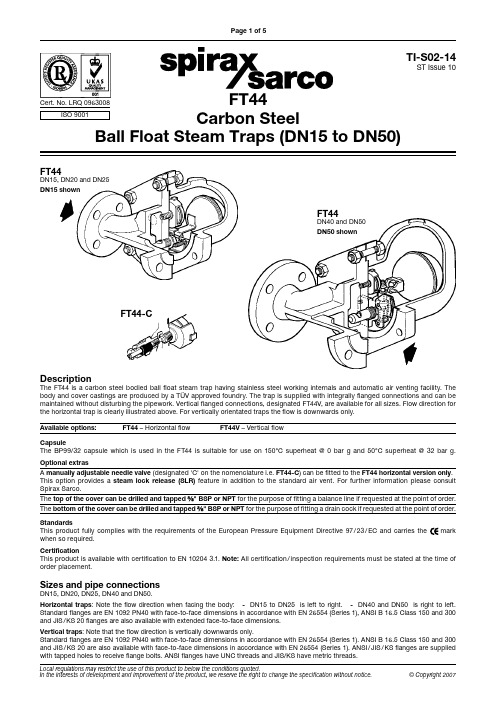
FT44 Carbon Steel Ball Float Steam Traps (DN15 to DN50)
TI-S02-14 ST Issue 10
Page 3 of 5
FT44
DN15, DN20 and3
18 17
8
4
10
2
1
3 18
17
8
4
9 12 6
Capsule The BP99/32 capsule which is used in the FT44 is suitable for use on 150°C superheat @ 0 bar g and 50°C superheat @ 32 bar g. Optional extras A manually adjustable needle valve (designated 'C' on the nomenclature i.e. FT44-C) can be fitted to the FT44 horizontal version only. This option provides a steam lock release (SLR) feature in addition to the standard air vent. For further information please consult Spirax Sarco. The top of the cover can be drilled and tapped " BSP or NPT for the purpose of fitting a balance line if requested at the point of order. The bottom of the cover can be drilled and tapped " BSP or NPT for the purpose of fitting a drain cock if requested at the point of order. Standards This product fully complies with the requirements of the European Pressure Equipment Directive 97 / 23 / EC and carries the when so required. mark
硬件模块单元测试报告-模板

硬件模块单元测试报告编制: 日期:审核: 日期: 批准: 日期:目录目录 (1)第一章概述 (3)1.1目的和范围 (3)1.2测试概述 (3)第二章测试资源及环境 (4)2.1 硬件配置 (4)2.2 测试设备清单 (4)2.3 测试环境 (4)2.4 测试方式 (4)第三章测试数据 (6)3.1 主控板测试 (6)3.1.1短路测试 (6)3.1.2直流电压、纹波测试 (6)3.1.3接口通讯信号测试 (8)3.1.3.1主控板与按键板打印部分 (8)3.1.3.2主控板与核心板 (8)3.1.3.3主控板与液晶屏 (8)3.1.3.4主控板与触摸屏 (9)3.1.3.5主控板与感光板 (10)3.1.3.6主控板对按键板指示灯部分检测信号 (10)3.1.3.8主控板与WIFI板 (10)3.1.4充电测试 (11)3.1.5电源转换效率测试 (11)3.1.5.1 5V电源转换效率测试 (11)2.1.5.2 +8V电源转换效率测试 (13)3.1.6 DC_DC带负载测试 (14)3.2 按键板测试 (15)3.2.1短路测试 (15)3.2.2直流电压、纹波测试 (15)3.2.3接口通讯信号测试 (15)3.2.3.1 按键板与打印机 (15)第一章概述1.1目的和范围本文描述H3硬件模块的测试方法和步骤, 本方案的来源是《H3硬件总体需求》和《H3硬件总体方案》适用范围是:1.2测试概述在硬件模块测试阶段, 测试人员根据细化后的方案进行集成测试, 测试的重点是接口, 主要包括以下几个方面:1.各个板卡接口和测试点电压纹波测试2.控制/检测信号逻辑状态分析第二章测试资源及环境2.1 硬件配置2.3 测试环境环境温度: 0-55℃;大气压力: 700hPa~1060hPa;相对湿度:15% ~ 95%, 非凝2.4 测试方式内部测试第三章测试数据3.1 主控板测试3.1.1短路测试3.1.3接口通讯信号测试3.1.3.1主控板与按键板打印部分3.1.3.2主控板与核心板3.1.3.3主控板与液晶屏3.1.3.4主控板与触摸屏3.1.3.5主控板与感光板3.1.3.8主控板与WIFI板3.1.4充电测试使用电源交流100~240Vac 50Hz/60Hz 使用内置锂电池 12.6V/2600mA3.1.6 DC_DC带负载测试3.2 按键板测试3.2.1短路测试3.2.3接口通讯信号测试3.2.3.1 按键板与打印机。
100-ES1-11 电子遥控开关操作说明
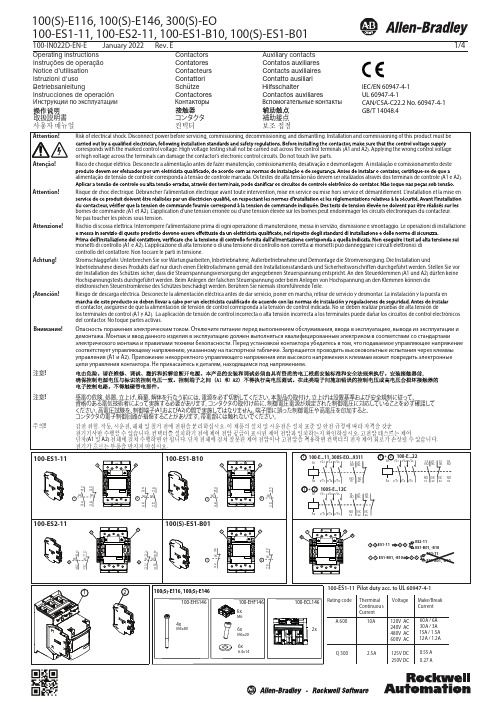
100-IN022D-EN-EJanuary 2022Rev. E1/4100(S)-E116, 100(S)-E146, 300(S)-EOOperating instructions Instruções de operação Notice d’utilisation Istruzioni d'uso BetriebsanleitungContactors Contatores Contacteurs Contattori Schütze Auxiliary contacts Contatos auxiliares Contacts auxiliaires Contatto ausiliari HilfsschalterInstrucciones de operación Contactores Contactos auxiliaresAttention! Attenzione! Achtung!¡Atención!Внимание!100-ES1-11, 100-ES2-11, 100-ES1-B10, 100(S)-ES1-B01Atenção!Инструкции по эксплуатацииКонтакторыВспомогательные контактыIEC/EN 60947-4-1UL 60947-4-1CAN/CSA-C22.2 No. 60947-4-1GB/T 14048.41523A1A2ON OFF_N COM 960V95+24 V Contactor StartSt opSupply voltageRelayX Note: Emergency stop should disconnect A1 and A2Code ED and EN built-in PLC interfaceOperation is controlled by separate logic control signals from, for instance, a PLC. Use of logic control requires a steady supply voltage on A1 and A2 within the rated voltage range, as described forcode KJ, KY, KD and KN (J, Y, D, B). The function of the logic control signal will no longer be guaranteed when the supply voltage on A1 and A2 is removed.The logic control signals are operated with 24V DC. There are two control signals (ON and OFF_N) and a common reference (COM). For the control signals, the function is guaranteed from 15V DC (6mA) to 33V DC (20mA).The contactor is closed by a control signal ON and opened by removal of control signal from OFF_N. The functions are described in diagram below. “1” means 24V DC between the control signal and COM. “0” means no voltage between the control signal and COM. Minimum control signal pulse length for opening and closing is 10ms. To connect the PLC interface, use cable dimension of max 1.5mm 2.General100(S)-E and 300(S)-EO contactors are if tted with an electronic interface. For a given coil, this allows the contactor to accept a very wide voltage range.Code KJ, KD, KN (J, Y, D, B)Operation is done, as with conventional contactors, by applying and removing supply voltage on A1 and A2. Closing 85% and opening at 55% of the lower nominal voltage limit, which is indicated in the functional diagram.When used with switches the wiring can be done according to diagram above4/4TYPE100(S)-E116FLAHerm. ref. comp,AC-8a 1168001602001601050LRA 100(S)-E146Ballast, A C-5a/Resistance air heatingElevator duty54541010010100Circuit Breaker A Fuse A/Class65100100100Max Short Circuit Current at 480V (kA)25356510018222550140G-J 140G-J2140G-J3140G-J6140G-J0510101001001006525200/J 200/J 140G-J6140G-J Type 2250/J250/RK5Max Short Circuit Current at 600V (kA)Circuit Breaker AFuse A/Class Max Short Circuit Current at 208-240V (kA)Max Short Circuit Current at 480V (kA)Type 1Max Short Circuit Current at 600V (kA)For applications above 690V, terminal shrouds 100-ETS146L should be used.UL/CSMax 600VAC, 50/60 Hz:2001601050300(S)-EO 54100(S)-E116, 100(S)-E146, 300(S)-EO100(S)-E116, 100(S)-E146, 300(S)-EOAccording to UL 60947-4-1 Use wire Cu 75 only. Use built-in cable clamps or UL recognized compression lugs. Enclosure with min. dimension 24 by 20 by 10 inches should be used. Suitable for use on a circuit capable of delivering not more than the max symmetrical amperes at the max voltage shown in the table below.Copyright © 2022 Rockwell Automation, Inc. All Rights Reserved. Printed in Sweden.Allen-Bradley, Rockwell Software, and Rockwell Automation are trademarks of Rockwell Automation, Inc.Trademarks not belonging to Rockwell Automation are property of their respective companies.Rockwell Automation maintains current product environmental information on its website at /rockwellautomation/about-us/sustainability-ethics/product-environmental-compliance.page.DIR 10002941731 (Version 04)Publication 100-IN022D-EN-E January, 2022。
Opone收发器
第一部分光纤收发器FT-100A 快速以太网光纤收发器系列FT-101A快速以太网光纤收发器系列FT-200A千兆以太网光纤收发器系列FT-200千兆以太网光纤收发器系列FT-120A双电口光纤收发器系列FT-150A四电口光纤收发器系列FTC-8光纤收发器机箱FTC-14光纤收发器机架FTC-16光纤收发器机架FT-100A 快速以太网光纤收发器系列概述:OpOne FT-100A为10/100Mbps自适应快速以太网光纤收发器(亦称光电介质转换器),可将10Base-T和100Base-TX双绞线电信号同100Base-FX光信号进行相互转换。
使网络的传输距离从铜线100m的极限扩展到120Km(单模全双工方式)。
支持两种不同的网络连接媒体类型:10/100Base-TX和100Base-FX,通过使用交换技术和存储转发技术来实现两种网络连接媒体之间的数据传输。
支持双纤多模、双纤单模和单纤单模多种光纤传输。
特点:自动适应10Mbps和100Mbps环境,便于网络的升级内置高效交换核心,实现流量控制,减少广播包支持全双工和半双工传输模式,能自动协商支持双绞线口自动交叉,方便系统调试安装支持最长1552byte超长数据包传输支持VLAN标签超长数据包传输支持QoS,保证VOIP数据包传输支持STP生成树,构成冗余网络低功耗,低发热,能长时间稳定工作;支持双纤多模、双纤单模和单纤单模多种光纤口选择,扩展了用户的需求。
产品图片:FT-100A(双纤单/多模外置电源) FT-100APS(单纤单模内置电源) FT-100AC(双纤单纤单模块卡)参数规格接入方式10/100Mbps标准IEEE802.3 10Base-T Ethernet,IEEE802.3u,100Base-TX/FX Fast Ethernet, IEEE802.3x Flow control,IEEE802.1q VLAN,IEEE802.1p QoS,IEEE802.1d Spanning Tree波长850nm/1310nm/1550nm传输距离双纤多模:2Km,双纤单模:25/40/60/80/100/120Km,单纤单模:25/40/60/80/100Km五类双绞线:100m端口1个RJ45口:连接STP/UTP五类双绞线1个光纤口:多模—SC或ST(光纤尺寸50、62.5/125μm)订购信息:FT-101A快速以太网光纤收发器系列概述:OpOne FT-101A为10/100M自适应快速以太网光纤收发器(亦称光电介质转换器),可将10Base-T和100Base-TX双绞线电信号同100Base-FX光信号进行相互转换。
stps40h100cw参数

s t p s 40h 100c w 参数
S S T T P P S S 4400H H 110000C C W W 是是一一种种二二极极管管,,它它具具有有以以下下参参数数::
11.. 最最大大正正向向电电压压((V V r r r r m m ))::110000V V
22.. 平平均均整整流流电电流流((I I o o ))::2200A A
33.. 峰峰值值正正向向脉脉冲冲电电流流((I I F F S S M M ))::220000A A
44.. 动动态态阻阻抗抗((V V F F ))::11..00V V
55.. 极极间间电电流流((I I R R M M ))::110000μμA A
66.. 反反向向击击穿穿电电压压((V V R R ))::110000V V
77.. 正正向向节节流流电电压压((V V f f ))::00..77V V
这这些些参参数数为为了了帮帮助助工工程程师师正正确确选选择择并并使使用用S S T T P P S S 4400H H 110000C C W W 二二极极管管。
请请注注意意,,对对于于任任何何具具体体应应用用,,建建议议查查阅阅S S T T P P S S 4400H H 110000C C W W 的的数数据据手手册册以以获获取取更更详详细细和和准准确确的的信信息息。
- 1、下载文档前请自行甄别文档内容的完整性,平台不提供额外的编辑、内容补充、找答案等附加服务。
- 2、"仅部分预览"的文档,不可在线预览部分如存在完整性等问题,可反馈申请退款(可完整预览的文档不适用该条件!)。
- 3、如文档侵犯您的权益,请联系客服反馈,我们会尽快为您处理(人工客服工作时间:9:00-18:30)。
®1/7Table 1: Main Product CharacteristicsI F(AV) 1 A V RRM 100 V T j (max)175°C V F (max)0.62 VSTPS1H100HIGH VOLTAGE POWER SCHOTTKY RECTIFIERREV. 5Table 3: Absolute Ratings (limiting values)Symbol Parameter Value Unit V RRM Repetitive peak reverse voltage 100V I F(RMS)RMS forward voltage 10A I F(AV)Average forward currentT L = 160°C δ = 0.51A I FSM Surge non repetitive forward current tp = 10ms sinusoidal 50A I RRM Repetitive peak reverse current tp = 2µs F = 1kHz square 1A I RSM Non repetitive peak reverse current tp = 100µs square 1A P ARM Repetitive peak avalanche power tp = 1µs Tj = 25°C1500W T stg Storage temperature range-65 to + 175°C T j Maximum operating junction temperature *175°C dV/dtCritical rate of rise of reverse voltage10000V/µs* : thermal runaway condition for a diode on its own heatsinkdPtot dTj ---------------1Rth j a –()------------------------->August 2004FEATURES AND BENEFITS■Negligible switching losses■High junction temperature capability ■Low leakage cuurent■G ood trade-off between leakage current and forward voltage drop■Avalanche capability specifiedDESCRIPTIONSchottky rectifiers designed for high frequency miniature Switched Mode Power Supplies such as adaptators and on board DC/DC converters.Packaged in SMA or SMB.Table 2: Order CodesPart Number Marking STPS1H100A S11STPS1H100UG11捷多邦,您值得信赖的PCB打样专家!STPS1H1002/7Table 4: Thermal Resistance Table 5: Static Electrical Characteristics Pulse test:* tp = 5 ms, δ < 2%** tp = 380 µs, δ < 2%To evaluate the conduction losses use the following equation: P = 0.54 x I F(AV) + 0.08 I F 2(RMS)Symbol ParameterValue Unit R th(j-l)Junction to leadSMA 30°C/WSMB25Symbol Parameter Tests conditions Min.Typ Max.Unit I R *Reverse leakage currentT j = 25°CV R = V RRM 4µA T j = 125°C0.20.5mAV F **Forward voltage dropT j = 25°CI F = 1A 0.77VT j = 125°C 0.580.62T j = 25°C I F = 2A0.86T j = 125°C0.650.7Figure 1: Average forward power dissipation versus average forward currentFigure 2: Average forward current versus ambient temperature (δ = 0.5)Figure 3: Normalized avalanche power derating versus pulse durationFigure 4: Normalized avalanche powerderating versus junction temperatureSTPS1H1003/7Figure 5: Non repetitive surge peak forward current versus overload duration (maximum values) (SMA)Figure 6: Non repetitive surge peak forward current versus overload duration (maximum values) (SMB)Figure 7: Relative variation of thermal impedance junction to ambient versus pulse duration (epoxy printed circuit board,e(Cu)=35µm, recommended pad layout) (SMA)Figure 8: Relative variation of thermal impedance junction to ambient versus pulse duration (epoxy printed circuit board,e(Cu)=35µm, recommended pad layout) (SMB)Figure 9: Reverse leakage current versus reverse voltage applied (typical values)Figure 10: Junction capacitance versus reverse voltage applied (typical values)STPS1H1004/7Figure 11: Forward voltage drop versus forward current (maximum values)Figure 12: Thermal resistance junction to ambient versus copper surface under each lead (Epoxy printed circuit board FR4, copper thickness: 35µm) (SMA)Figure 13: Thermal resistance junction to ambient versus copper surface under each lead (Epoxy printed circuit board FR4, copper thickness: 35µm) (SMB)STPS1H100 Figure 14: SMA Package Mechanical DataFigure 15: SMA Foot Print Dimensions(in millimeters)5/7STPS1H100Figure 16: SMB Package Mechanical DataFigure 17: SMB Foot Print Dimensions (in millimeters)6/7STPS1H1007/7Information furnished is believed to be accurate and reliable. However, STMicroelectronics assumes no responsibility for the consequences of use of such information nor for any infringement of patents or other rights of third parties which may result from its use. No license is granted by implication or otherwise under any patent or patent rights of STMicroelectronics. Specifications mentioned in this publication are subject to change without notice. This publication supersedes and replaces all information previously supplied. STMicroelectronics products are not authorized for use as critical components in life support devices or systems without express written approval of STMicroelectronics.The ST logo is a registered trademark of STMicroelectronics. All other names are the property of their respective owners© 2004 STMicroelectronics - All rights reservedSTMicroelectronics group of companiesAustralia - Belgium - Brazil - Canada - China - Czech Republic - Finland - France - Germany - Hong Kong - India - Israel - Italy - Japan -Malaysia - Malta - Morocco - Singapore - Spain - Sweden - Switzerland - United Kingdom - United States of AmericaTable 6: Ordering Information■Band indicates cathode ■Epoxy meets UL94, V0Ordering type Marking Package Weight Base qty Delivery mode STPS1H100A S11SMA 0.068 g 5000Tape & reel STPS1H100UG11SMB 0.107 g 2500Tape & reelTable 7: Revision HistoryDate Revision Description of ChangesJul-20034ALast update.Aug-20045SMA package dimensions update. Reference A1 max.changed from 2.70mm (0.106inc.) to 2.03mm (0.080).。