GS12U05-P1I中文资料
R12I05资料

Electrical Specifications (measured at TA = 25°C, at nominal input voltage and rated output current unless otherwise specified)
Input Voltage Range VIN (continuous operation) Reflected Ripple Current (depending on the type) Voltage Set Point Accuracy Line Regulation (high VIN to low VIN) Load regulation (depending on the type) Ripple and Noise (BW=DC to 20MHz) (depending on the type) Isolation Voltage (flash tested for 1 second) Test Voltage (50Hz, 10 seconds) Resistance (Viso = 500V) Switching Frequency Package Weight Storage Temperature Range Operating Temperature Range (all output types) Case Temperature Above Ambient (depending on the type) MTTF 1) (depending on the type) –40°C +25°C +85°C SIP types 5V types 12V types 4.5VDC min. / 5.5VDC max. 10.8VDC min. / 13.2VDC max. 23 mA p-p min. to 38 mA p-p max. see Tolerance Envelope 1.0% min. / 1.2% max. of VIN 3.7% min. / 8.5% max. 45mVp-p min. / 200mVp-p max. 1000VDC min. 1000 Vpk min. 10 GΩ min. 90kHz typ. 2.0 g –50°C to +130°C –40°C min. to +85°C max. (see graph) +36°C min. / +45°C max. 417kHrs min. / 3970kHrs max. 328kHrs min. / 2327kHrs max. 222kHrs min. / 934kHrs max.
Silicon Laboratories C8051F380 1 2 3 4 5 6 7 C USB

-10 位 ADC(仅 C8051F380/1/2/3/C)•高达 500ksps•内建模拟多路复用器,单端和差分模式•VREF 来自外部引脚、内部参考或 V DD•内建温度传感器•外部转换启动输入选项-两个比较器-内部参考电压(仅 C8051F380/1/2/3/C)-掉电检测器和上电复位电路USB 功能控制器-符合 USB 规格 2.0-全速 (12Mbps) 或低速 (1.5Mbps) 运行-集成时钟恢复;全速或低速无需外部晶体-支持八个灵活的终端-1kB USB 缓冲存储器-集成收发器;无需外部电阻片上调试-片上调试电路提供全速、非侵入式的系统内调试(无需仿真器)-提供断点、单步执行、检查/修改内存和寄存器-比使用 ICE 芯片、目标仿真头和仿真插座的仿真系统有更优越的性能电源电压输入: 2.7 至 5.25V-使用片内稳压器时,支持的电压范围为 2.7~5.25V -流水线指令体系结构;70% 指令的执行时间为 1 个或2个系统时钟-高达 48 MIPS 的操作-扩展的中断处理程序内存-4352 或 2304字节 RAM-64、32 或 16kB 闪存;可在系统内编程的 512 字节扇区数字外围设备-40/25 个端口 I/O;全部能承受 5V 高灌电流-硬件增强型SPI™、两个 I2C/SMBus™ 和两个增强型UART 串口-六个通用 16 位计数器/定时器-16 位可编程计数器阵列 (PCA),有五个采集/比较模块-外部存储器接口 (EMIF)时钟源-内部振荡器:启用时钟恢复时精度为 ±0.25%。
支持所有USB 和 UART 模式-外部振荡器:晶体、RC、C 或时钟(1 或 2 引脚模式)-低频 (80kHz) 内部振荡器-在运行中可切换时钟源封装-48 引脚 TQFP (C8051F380/2/4/6)-32 引脚 LQFP (C8051F381/3/5/7/C)-5x5mm 32 引脚 QFN (C8051F381/3/5/7/C)温度范围: –40 至 +85°CC8051F380/1/2/3/4/5/6/7/CC8051F380/1/2/3/4/5/6/7/CTable of Contents1. System Overview (16)2. C8051F34x Compatibility (20)2.1. Hardware Incompatibilities (21)3. Pinout and Package Definitions (22)4. Typical Connection Diagrams (34)4.1. Power (34)4.2. USB (36)4.3. Voltage Reference (VREF) (36)5. Electrical Characteristics (37)5.1. Absolute Maximum Specifications (37)5.2. Electrical Characteristics (38)6. 10-Bit ADC (ADC0, C8051F380/1/2/3/C only) (46)6.1. Output Code Formatting (47)6.3. Modes of Operation (50)6.3.1. Starting a Conversion (50)6.3.2. Tracking Modes (51)6.3.3. Settling Time Requirements (52)6.4. Programmable Window Detector (56)6.4.1. Window Detector Example (58)6.5. ADC0 Analog Multiplexer (C8051F380/1/2/3/C only) (59)7. Voltage Reference Options (62)8. Comparator0 and Comparator1 (64)8.1. Comparator Multiplexers (71)9. Voltage Regulators (REG0 and REG1) (74)9.1. Voltage Regulator (REG0) (74)9.1.1. Regulator Mode Selection (74)9.1.2. VBUS Detection (74)9.2. Voltage Regulator (REG1) (74)10. Power Management Modes (76)10.1. Idle Mode (76)10.2. Stop Mode (77)10.3. Suspend Mode (77)11. CIP-51 Microcontroller (79)11.1. Instruction Set (80)11.1.1. Instruction and CPU Timing (80)11.2. CIP-51 Register Descriptions (85)12. Prefetch Engine (88)13. Memory Organization (89)13.1. Program Memory (91)13.2. Data Memory (91)13.3. General Purpose Registers (92)13.4. Bit Addressable Locations (92)13.5. Stack (92)C8051F380/1/2/3/4/5/6/7/C14. External Data Memory Interface and On-Chip XRAM (93)14.1. Accessing XRAM (93)14.1.1. 16-Bit MOVX Example (93)14.1.2. 8-Bit MOVX Example (93)14.2. Accessing USB FIFO Space (94)14.3. Configuring the External Memory Interface (95)14.4. Port Configuration (95)14.5. Multiplexed and Non-multiplexed Selection (98)14.5.1. Multiplexed Configuration (98)14.5.2. Non-multiplexed Configuration (98)14.6. Memory Mode Selection (100)14.6.1. Internal XRAM Only (100)14.6.2. Split Mode without Bank Select (100)14.6.3. Split Mode with Bank Select (101)14.6.4. External Only (101)14.7. Timing (102)14.7.1. Non-multiplexed Mode (104)14.7.1.1. 16-bit MOVX: EMI0CF[4:2] = 101, 110, or 111 (104)14.7.1.2. 8-bit MOVX without Bank Select: EMI0CF[4:2] = 101 or 111 (105)14.7.1.3. 8-bit MOVX with Bank Select: EMI0CF[4:2] = 110 (106)14.7.2. Multiplexed Mode (107)14.7.2.1. 16-bit MOVX: EMI0CF[4:2] = 001, 010, or 011 (107)14.7.2.2. 8-bit MOVX without Bank Select: EMI0CF[4:2] = 001 or 011 (108)14.7.2.3. 8-bit MOVX with Bank Select: EMI0CF[4:2] = 010 (109)15. Special Function Registers (111)15.1. 13.1. SFR Paging (111)16. Interrupts (118)16.1. MCU Interrupt Sources and Vectors (119)16.1.1. Interrupt Priorities (119)16.1.2. Interrupt Latency (119)16.2. Interrupt Register Descriptions (119)16.3. INT0 and INT1 External Interrupt Sources (127)17. Reset Sources (129)17.1. Power-On Reset (130)17.2. Power-Fail Reset / VDD Monitor (131)17.3. External Reset (132)17.4. Missing Clock Detector Reset (132)17.5. Comparator0 Reset (132)17.6. PCA Watchdog Timer Reset (133)17.7. Flash Error Reset (133)17.8. Software Reset (133)17.9. USB Reset (133)18. Flash Memory (135)18.1. Programming The Flash Memory (135)18.1.1. Flash Lock and Key Functions (135)C8051F380/1/2/3/4/5/6/7/C18.1.2. Flash Erase Procedure (135)18.1.3. Flash Write Procedure (136)18.2. Non-Volatile Data Storage (137)18.3. Security Options (137)19. Oscillators and Clock Selection (142)19.1. System Clock Selection (143)19.2. USB Clock Selection (143)19.3. Programmable Internal High-Frequency (H-F) Oscillator (145)19.3.1. Internal Oscillator Suspend Mode (145)19.4. Clock Multiplier (147)19.5. Programmable Internal Low-Frequency (L-F) Oscillator (148)19.5.1. Calibrating the Internal L-F Oscillator (148)19.6. External Oscillator Drive Circuit (149)19.6.1. External Crystal Mode (149)19.6.2. External RC Example (151)19.6.3. External Capacitor Example (151)20. Port Input/Output (153)20.1. Priority Crossbar Decoder (154)20.2. Port I/O Initialization (158)20.3. General Purpose Port I/O (161)21. Universal Serial Bus Controller (USB0) (172)21.1. Endpoint Addressing (172)21.2. USB Transceiver (173)21.3. USB Register Access (175)21.4. USB Clock Configuration (179)21.5. FIFO Management (181)21.5.1. FIFO Split Mode (181)21.5.2. FIFO Double Buffering (182)21.5.1. FIFO Access (182)21.6. Function Addressing (183)21.7. Function Configuration and Control (183)21.8. Interrupts (186)21.9. The Serial Interface Engine (193)21.10. Endpoint0 (193)21.10.1. Endpoint0 SETUP Transactions (193)21.10.2. Endpoint0 IN Transactions (193)21.10.3. Endpoint0 OUT Transactions (194)21.11. Configuring Endpoints1-3 (196)21.12. Controlling Endpoints1-3 IN (197)21.12.1. Endpoints1-3 IN Interrupt or Bulk Mode (197)21.12.2. Endpoints1-3 IN Isochronous Mode (198)21.13. Controlling Endpoints1-3 OUT (201)21.13.1. Endpoints1-3 OUT Interrupt or Bulk Mode (201)21.13.2. Endpoints1-3 OUT Isochronous Mode (201)22. SMBus0 and SMBus1 (I2C Compatible) (205)C8051F380/1/2/3/4/5/6/7/C22.1. Supporting Documents (206)22.2. SMBus Configuration (206)22.3. SMBus Operation (206)22.3.1. Transmitter Vs. Receiver (207)22.3.2. Arbitration (207)22.3.3. Clock Low Extension (207)22.3.4. SCL Low Timeout (207)22.3.5. SCL High (SMBus Free) Timeout (208)22.4. Using the SMBus (208)22.4.1. SMBus Configuration Register (208)22.4.2. SMBus Timing Control Register (210)22.4.3. SMBnCN Control Register (214)22.4.3.1. Software ACK Generation (214)22.4.3.2. Hardware ACK Generation (214)22.4.4. Hardware Slave Address Recognition (217)22.4.5. Data Register (221)22.5. SMBus Transfer Modes (223)22.5.1. Write Sequence (Master) (223)22.5.2. Read Sequence (Master) (224)22.5.3. Write Sequence (Slave) (225)22.5.4. Read Sequence (Slave) (226)22.6. SMBus Status Decoding (226)23. UART0 (232)23.1. Enhanced Baud Rate Generation (233)23.2. Operational Modes (234)23.2.1. 8-Bit UART (234)23.2.2. 9-Bit UART (235)23.3. Multiprocessor Communications (236)24. UART1 (240)24.1. Baud Rate Generator (241)24.2. Data Format (242)24.3. Configuration and Operation (243)24.3.1. Data Transmission (243)24.3.2. Data Reception (243)24.3.3. Multiprocessor Communications (244)25. Enhanced Serial Peripheral Interface (SPI0) (250)25.1. Signal Descriptions (251)25.1.1. Master Out, Slave In (MOSI) (251)25.1.2. Master In, Slave Out (MISO) (251)25.1.3. Serial Clock (SCK) (251)25.1.4. Slave Select (NSS) (251)25.2. SPI0 Master Mode Operation (251)25.3. SPI0 Slave Mode Operation (253)25.4. SPI0 Interrupt Sources (254)25.5. Serial Clock Phase and Polarity (254)25.6. SPI Special Function Registers (256)26. Timers (263)26.1. Timer 0 and Timer 1 (266)26.1.1. Mode 0: 13-bit Counter/Timer (266)26.1.2. Mode 1: 16-bit Counter/Timer (267)26.1.3. Mode 2: 8-bit Counter/Timer with Auto-Reload (267)26.1.4. Mode 3: Two 8-bit Counter/Timers (Timer 0 Only) (268)26.2. Timer 2 (274)26.2.1. 16-bit Timer with Auto-Reload (274)26.2.2. 8-bit Timers with Auto-Reload (275)26.2.3. Timer 2 Capture Modes: USB Start-of-Frame or LFO Falling Edge (275)26.3. Timer 3 (281)26.3.1. 16-bit Timer with Auto-Reload (281)26.3.2. 8-bit Timers with Auto-Reload (282)26.3.3. Timer 3 Capture Modes: USB Start-of-Frame or LFO Falling Edge (282)26.4. Timer 4 (288)26.4.1. 16-bit Timer with Auto-Reload (288)26.4.2. 8-bit Timers with Auto-Reload (289)26.5. Timer 5 (293)26.5.1. 16-bit Timer with Auto-Reload (293)26.5.2. 8-bit Timers with Auto-Reload (294)27. Programmable Counter Array (298)27.1. PCA Counter/Timer (299)27.2. PCA0 Interrupt Sources (300)27.3. Capture/Compare Modules (301)27.3.1. Edge-triggered Capture Mode (302)27.3.2. Software Timer (Compare) Mode (303)27.3.3. High-Speed Output Mode (304)27.3.4. Frequency Output Mode (305)27.3.5. 8-bit Pulse Width Modulator Mode (306)27.3.6. 16-Bit Pulse Width Modulator Mode (307)27.4. Watchdog Timer Mode (308)27.4.1. Watchdog Timer Operation (308)27.4.2. Watchdog Timer Usage (309)27.5. Register Descriptions for PCA0 (311)28. C2 Interface (316)28.1. C2 Interface Registers (316)28.2. C2 Pin Sharing (319)Document Change List (320)Contact Information (321)List of FiguresFigure1.1. C8051F380/2/4/6 Block Diagram (18)Figure1.2. C8051F381/3/5/7/C Block Diagram (19)Figure3.1. TQFP-48 Pinout Diagram (Top View) (25)Figure3.2. TQFP-48 Package Diagram (26)Figure3.3. TQFP-48 Recommended PCB Land Pattern (27)Figure3.4. LQFP-32 Pinout Diagram (Top View) (28)Figure3.5. LQFP-32 Package Diagram (29)Figure3.6. LQFP-32 Recommended PCB Land Pattern (30)Figure3.7. QFN-32 Pinout Diagram (Top View) (31)Figure3.8. QFN-32 Package Drawing (32)Figure3.9. QFN-32 Recommended PCB Land Pattern (33)Figure4.1. Connection Diagram with Voltage Regulator Used and No USB (34)Figure4.2. Connection Diagram with Voltage Regulator Not Used and No USB (34)Figure4.3. Connection Diagram with Voltage Regulator Used and USB Connected (Bus-Powered) (35)Figure4.4. Connection Diagram with Voltage Regulator Used and USB Connected (Self-Powered) (35)Figure4.5. Connection Diagram for USB Pins (36)Figure4.6. Connection Diagram for Internal Voltage Reference (36)Figure6.1. ADC0 Functional Block Diagram (46)Figure6.2. Typical Temperature Sensor Transfer Function (48)Figure6.3. Temperature Sensor Error with 1-Point Calibration (49)Figure6.4. 10-Bit ADC Track and Conversion Example Timing (51)Figure6.5. ADC0 Equivalent Input Circuits (52)Figure6.6. ADC Window Compare Example: Right-Justified Data (58)Figure6.7. ADC Window Compare Example: Left-Justified Data (58)Figure7.1. Voltage Reference Functional Block Diagram (62)Figure8.1. Comparator0 Functional Block Diagram (64)Figure8.2. Comparator1 Functional Block Diagram (65)Figure8.3. Comparator Hysteresis Plot (66)Figure8.4. Comparator Input Multiplexer Block Diagram (71)Figure11.1. CIP-51 Block Diagram (79)Figure13.1. On-Chip Memory Map for 64kB Devices (C8051F380/1/4/5) (89)Figure13.2. On-Chip Memory Map for 32kB Devices (C8051F382/3/6/7) (90)Figure13.3. On-Chip Memory Map for 16kB Devices (C8051F38C) (91)Figure14.1. USB FIFO Space and XRAM Memory Map with USBFAE set to ‘1’ (94)Figure14.2. Multiplexed Configuration Example (98)Figure14.3. Non-multiplexed Configuration Example (99)Figure14.4. EMIF Operating Modes (100)Figure14.5. Non-Multiplexed 16-bit MOVX Timing (104)Figure14.6. Non-multiplexed 8-bit MOVX without Bank Select Timing (105)Figure14.7. Non-multiplexed 8-bit MOVX with Bank Select Timing (106)Figure14.8. Multiplexed 16-bit MOVX Timing (107)C8051F380/1/2/3/4/5/6/7/CFigure14.9. Multiplexed 8-bit MOVX without Bank Select Timing (108)Figure14.10. Multiplexed 8-bit MOVX with Bank Select Timing (109)Figure17.1. Reset Sources (129)Figure17.2. Power-On and VDD Monitor Reset Timing (130)Figure18.1. Flash Program Memory Map and Security Byte (137)Figure19.1. Oscillator Options (142)Figure19.2. External Crystal Example (150)Figure20.1. Port I/O Functional Block Diagram (Port 0 through Port 3) (153)Figure20.2. Port I/O Cell Block Diagram (154)Figure20.3. Peripheral Availability on Port I/O Pins (155)Figure20.4. Crossbar Priority Decoder in Example Configuration(No Pins Skipped) (156)Figure20.5. Crossbar Priority Decoder in Example Configuration (3 Pins Skipped) (157)Figure21.1. USB0 Block Diagram (172)Figure21.2. USB0 Register Access Scheme (175)Figure21.3. USB FIFO Allocation (181)Figure22.1. SMBus Block Diagram (205)Figure22.2. Typical SMBus Configuration (206)Figure22.3. SMBus Transaction (207)Figure22.4. Typical SMBus SCL Generation (209)Figure22.5. Typical Master Write Sequence (223)Figure22.6. Typical Master Read Sequence (224)Figure22.7. Typical Slave Write Sequence (225)Figure22.8. Typical Slave Read Sequence (226)Figure23.1. UART0 Block Diagram (232)Figure23.2. UART0 Baud Rate Logic (233)Figure23.3. UART Interconnect Diagram (234)Figure23.4. 8-Bit UART Timing Diagram (234)Figure23.5. 9-Bit UART Timing Diagram (235)Figure23.6. UART Multi-Processor Mode Interconnect Diagram (236)Figure24.1. UART1 Block Diagram (240)Figure24.2. UART1 Timing Without Parity or Extra Bit (242)Figure24.3. UART1 Timing With Parity (242)Figure24.4. UART1 Timing With Extra Bit (242)Figure24.5. Typical UART Interconnect Diagram (243)Figure24.6. UART Multi-Processor Mode Interconnect Diagram (244)Figure25.1. SPI Block Diagram (250)Figure25.2. Multiple-Master Mode Connection Diagram (252)Figure25.3. 3-Wire Single Master and 3-Wire Single Slave Mode Connection Diagram (252)Figure25.4. 4-Wire Single Master Mode and 4-Wire Slave Mode Connection Diagram (253)Figure25.5. Master Mode Data/Clock Timing (255)Figure25.6. Slave Mode Data/Clock Timing (CKPHA = 0) (255)C8051F380/1/2/3/4/5/6/7/C Figure25.7. Slave Mode Data/Clock Timing (CKPHA = 1) (256)Figure25.8. SPI Master Timing (CKPHA = 0) (260)Figure25.9. SPI Master Timing (CKPHA = 1) (260)Figure25.10. SPI Slave Timing (CKPHA = 0) (261)Figure25.11. SPI Slave Timing (CKPHA = 1) (261)Figure26.1. T0 Mode 0 Block Diagram (267)Figure26.2. T0 Mode 2 Block Diagram (268)Figure26.3. T0 Mode 3 Block Diagram (269)Figure26.4. Timer 2 16-Bit Mode Block Diagram (274)Figure26.5. Timer 2 8-Bit Mode Block Diagram (275)Figure26.6. Timer2 Capture Mode (T2SPLIT = 0) (276)Figure26.7. Timer2 Capture Mode (T2SPLIT = 0) (277)Figure26.8. Timer 3 16-Bit Mode Block Diagram (281)Figure26.9. Timer 3 8-Bit Mode Block Diagram (282)Figure26.10. Timer3 Capture Mode (T3SPLIT = 0) (283)Figure26.11. Timer3 Capture Mode (T3SPLIT = 0) (284)Figure26.12. Timer 4 16-Bit Mode Block Diagram (288)Figure26.13. Timer 4 8-Bit Mode Block Diagram (289)Figure26.14. Timer 5 16-Bit Mode Block Diagram (293)Figure26.15. Timer 5 8-Bit Mode Block Diagram (294)Figure27.1. PCA Block Diagram (298)Figure27.2. PCA Counter/Timer Block Diagram (299)Figure27.3. PCA Interrupt Block Diagram (300)Figure27.4. PCA Capture Mode Diagram (302)Figure27.5. PCA Software Timer Mode Diagram (303)Figure27.6. PCA High-Speed Output Mode Diagram (304)Figure27.7. PCA Frequency Output Mode (305)Figure27.8. PCA 8-Bit PWM Mode Diagram (306)Figure27.9. PCA 16-Bit PWM Mode (307)Figure27.10. PCA Module 4 with Watchdog Timer Enabled (308)Figure28.1. Typical C2 Pin Sharing (319)List of TablesTable1.1. Product Selection Guide (17)Table2.1. C8051F38x Replacement Part Numbers (20)Table3.1. Pin Definitions for the C8051F380/1/2/3/4/5/6/7/C (22)Table3.2. TQFP-48 Package Dimensions (26)Table3.3. TQFP-48 PCB Land Pattern Dimensions (27)Table3.4. LQFP-32 Package Dimensions (29)Table3.5. LQFP-32 PCB Land Pattern Dimensions (30)Table3.6. QFN-32 Package Dimensions (32)Table3.7. QFN-32 PCB Land Pattern Dimensions (33)Table5.1. Absolute Maximum Ratings (37)Table5.2. Global Electrical Characteristics (38)Table5.3. Port I/O DC Electrical Characteristics (39)Table5.4. Reset Electrical Characteristics (39)Table5.5. Internal Voltage Regulator Electrical Characteristics (40)Table5.6. Flash Electrical Characteristics (40)Table5.7. Internal High-Frequency Oscillator Electrical Characteristics (41)Table5.8. Internal Low-Frequency Oscillator Electrical Characteristics (41)Table5.9. External Oscillator Electrical Characteristics (41)Table5.10. ADC0 Electrical Characteristics (42)Table5.11. Temperature Sensor Electrical Characteristics (43)Table5.12. Voltage Reference Electrical Characteristics (43)Table5.13. Comparator Electrical Characteristics (44)Table5.14. USB Transceiver Electrical Characteristics (45)Table11.1. CIP-51 Instruction Set Summary (81)Table14.1. AC Parameters for External Memory Interface (110)Table15.1. Special Function Register (SFR) Memory Map (112)Table15.2. Special Function Registers (113)Table16.1. Interrupt Summary (120)Table21.1. Endpoint Addressing Scheme (173)Table21.2. USB0 Controller Registers (178)Table21.3. FIFO Configurations (182)Table22.1. SMBus Clock Source Selection (209)Table22.2. Minimum SDA Setup and Hold Times (210)Table22.3. Sources for Hardware Changes to SMBnCN (217)Table22.4. Hardware Address Recognition Examples (EHACK = 1) (218)Table22.5. SMBus Status Decoding: Hardware ACK Disabled (EHACK = 0) (227)Table22.6. SMBus Status Decoding: Hardware ACK Enabled (EHACK = 1) (229)Table23.1. Timer Settings for Standard Baud Rates Using Internal Oscillator (238)Table24.1. Baud Rate Generator Settings for Standard Baud Rates (241)Table25.1. SPI Slave Timing Parameters (262)Table27.1. PCA Timebase Input Options (299)Table27.2. PCA0CPM Bit Settings for PCA Capture/Compare Modules (301)Table27.3. Watchdog Timer Timeout Intervals1 (310)List of RegistersSFR Definition6.1. ADC0CF: ADC0 Configuration (53)SFR Definition6.2. ADC0H: ADC0 Data Word MSB (54)SFR Definition6.3. ADC0L: ADC0 Data Word LSB (54)SFR Definition6.4. ADC0CN: ADC0 Control (55)SFR Definition6.5. ADC0GTH: ADC0 Greater-Than Data High Byte (56)SFR Definition6.6. ADC0GTL: ADC0 Greater-Than Data Low Byte (56)SFR Definition6.7. ADC0LTH: ADC0 Less-Than Data High Byte (57)SFR Definition6.8. ADC0LTL: ADC0 Less-Than Data Low Byte (57)SFR Definition6.9. AMX0P: AMUX0 Positive Channel Select (60)SFR Definition6.10. AMX0N: AMUX0 Negative Channel Select (61)SFR Definition7.1. REF0CN: Reference Control (63)SFR Definition8.1. CPT0CN: Comparator0 Control (67)SFR Definition8.2. CPT0MD: Comparator0 Mode Selection (68)SFR Definition8.3. CPT1CN: Comparator1 Control (69)SFR Definition8.4. CPT1MD: Comparator1 Mode Selection (70)SFR Definition8.5. CPT0MX: Comparator0 MUX Selection (72)SFR Definition8.6. CPT1MX: Comparator1 MUX Selection (73)SFR Definition9.1. REG01CN: Voltage Regulator Control (75)SFR Definition10.1. PCON: Power Control (78)SFR Definition11.1. DPL: Data Pointer Low Byte (85)SFR Definition11.2. DPH: Data Pointer High Byte (85)SFR Definition11.3. SP: Stack Pointer (86)SFR Definition11.4. ACC: Accumulator (86)SFR Definition11.5. B: B Register (86)SFR Definition11.6. PSW: Program Status Word (87)SFR Definition12.1. PFE0CN: Prefetch Engine Control (88)SFR Definition14.1. EMI0CN: External Memory Interface Control (96)SFR Definition14.2. EMI0CF: External Memory Interface Configuration (97)SFR Definition14.3. EMI0TC: External Memory TIming Control (103)SFR Definition15.1. SFRPAGE: SFR Page (111)SFR Definition16.1. IE: Interrupt Enable (121)SFR Definition16.2. IP: Interrupt Priority (122)SFR Definition16.3. EIE1: Extended Interrupt Enable 1 (123)SFR Definition16.4. EIP1: Extended Interrupt Priority 1 (124)SFR Definition16.5. EIE2: Extended Interrupt Enable 2 (125)SFR Definition16.6. EIP2: Extended Interrupt Priority 2 (126)SFR Definition16.7. IT01CF: INT0/INT1 ConfigurationO (128)SFR Definition17.1. VDM0CN: VDD Monitor Control (132)SFR Definition17.2. RSTSRC: Reset Source (134)SFR Definition18.1. PSCTL: Program Store R/W Control (139)SFR Definition18.2. FLKEY: Flash Lock and Key (140)SFR Definition18.3. FLSCL: Flash Scale (141)SFR Definition19.1. CLKSEL: Clock Select (144)C8051F380/1/2/3/4/5/6/7/CSFR Definition19.2. OSCICL: Internal H-F Oscillator Calibration (145)SFR Definition19.3. OSCICN: Internal H-F Oscillator Control (146)SFR Definition19.4. CLKMUL: Clock Multiplier Control (147)SFR Definition19.5. OSCLCN: Internal L-F Oscillator Control (148)SFR Definition19.6. OSCXCN: External Oscillator Control (152)SFR Definition20.1. XBR0: Port I/O Crossbar Register 0 (159)SFR Definition20.2. XBR1: Port I/O Crossbar Register 1 (160)SFR Definition20.3. XBR2: Port I/O Crossbar Register 2 (161)SFR Definition20.4. P0: Port 0 (162)SFR Definition20.5. P0MDIN: Port 0 Input Mode (162)SFR Definition20.6. P0MDOUT: Port 0 Output Mode (163)SFR Definition20.7. P0SKIP: Port 0 Skip (163)SFR Definition20.8. P1: Port 1 (164)SFR Definition20.9. P1MDIN: Port 1 Input Mode (164)SFR Definition20.10. P1MDOUT: Port 1 Output Mode (165)SFR Definition20.11. P1SKIP: Port 1 Skip (165)SFR Definition20.12. P2: Port 2 (166)SFR Definition20.13. P2MDIN: Port 2 Input Mode (166)SFR Definition20.14. P2MDOUT: Port 2 Output Mode (167)SFR Definition20.15. P2SKIP: Port 2 Skip (167)SFR Definition20.16. P3: Port 3 (168)SFR Definition20.17. P3MDIN: Port 3 Input Mode (168)SFR Definition20.18. P3MDOUT: Port 3 Output Mode (169)SFR Definition20.19. P3SKIP: Port 3 Skip (169)SFR Definition20.20. P4: Port 4 (170)SFR Definition20.21. P4MDIN: Port 4 Input Mode (170)SFR Definition20.22. P4MDOUT: Port 4 Output Mode (171)SFR Definition21.1. USB0XCN: USB0 Transceiver Control (174)SFR Definition21.2. USB0ADR: USB0 Indirect Address (176)SFR Definition21.3. USB0DAT: USB0 Data (177)USB Register Definition21.4. INDEX: USB0 Endpoint Index (179)USB Register Definition21.5. CLKREC: Clock Recovery Control (180)USB Register Definition21.6. FIFOn: USB0 Endpoint FIFO Access (182)USB Register Definition21.7. FADDR: USB0 Function Address (183)USB Register Definition21.8. POWER: USB0 Power (185)USB Register Definition21.9. FRAMEL: USB0 Frame Number Low (186)USB Register Definition21.10. FRAMEH: USB0 Frame Number High (186)USB Register Definition21.11. IN1INT: USB0 IN Endpoint Interrupt (187)USB Register Definition21.12. OUT1INT: USB0 OUT Endpoint Interrupt (188)USB Register Definition21.13. CMINT: USB0 Common Interrupt (189)USB Register Definition21.14. IN1IE: USB0 IN Endpoint Interrupt Enable (190)USB Register Definition21.15. OUT1IE: USB0 OUT Endpoint Interrupt Enable (191)USB Register Definition21.16. CMIE: USB0 Common Interrupt Enable (192)USB Register Definition21.17. E0CSR: USB0 Endpoint0 Control (195)USB Register Definition21.18. E0CNT: USB0 Endpoint0 Data Count (196)C8051F380/1/2/3/4/5/6/7/C USB Register Definition21.19. EENABLE: USB0 Endpoint Enable (197)USB Register Definition21.20. EINCSRL: USB0 IN Endpoint Control Low (199)USB Register Definition21.21. EINCSRH: USB0 IN Endpoint Control High (200)USB Register Definition21.22. EOUTCSRL: USB0 OUT Endpoint Control Low Byte 202 USB Register Definition21.23. EOUTCSRH: USB0 OUT Endpoint Control High Byte (203)USB Register Definition21.24. EOUTCNTL: USB0 OUT Endpoint Count Low (203)USB Register Definition21.25. EOUTCNTH: USB0 OUT Endpoint Count High (204)SFR Definition22.1. SMB0CF: SMBus Clock/Configuration (211)SFR Definition22.2. SMB1CF: SMBus Clock/Configuration (212)SFR Definition22.3. SMBTC: SMBus Timing Control (213)SFR Definition22.4. SMB0CN: SMBus Control (215)SFR Definition22.5. SMB1CN: SMBus Control (216)SFR Definition22.6. SMB0ADR: SMBus0 Slave Address (218)SFR Definition22.7. SMB0ADM: SMBus0 Slave Address Mask (219)SFR Definition22.8. SMB1ADR: SMBus1 Slave Address (219)SFR Definition22.9. SMB1ADM: SMBus1 Slave Address Mask (220)SFR Definition22.10. SMB0DAT: SMBus Data (221)SFR Definition22.11. SMB1DAT: SMBus Data (222)SFR Definition23.1. SCON0: Serial Port 0 Control (237)SFR Definition23.2. SBUF0: Serial (UART0) Port Data Buffer (238)SFR Definition24.1. SCON1: UART1 Control (245)SFR Definition24.2. SMOD1: UART1 Mode (246)SFR Definition24.3. SBUF1: UART1 Data Buffer (247)SFR Definition24.4. SBCON1: UART1 Baud Rate Generator Control (248)SFR Definition24.5. SBRLH1: UART1 Baud Rate Generator High Byte (248)SFR Definition24.6. SBRLL1: UART1 Baud Rate Generator Low Byte (249)SFR Definition25.1. SPI0CFG: SPI0 Configuration (257)SFR Definition25.2. SPI0CN: SPI0 Control (258)SFR Definition25.3. SPI0CKR: SPI0 Clock Rate (259)SFR Definition25.4. SPI0DAT: SPI0 Data (259)SFR Definition26.1. CKCON: Clock Control (264)SFR Definition26.2. CKCON1: Clock Control 1 (265)SFR Definition26.3. TCON: Timer Control (270)SFR Definition26.4. TMOD: Timer Mode (271)SFR Definition26.5. TL0: Timer 0 Low Byte (272)SFR Definition26.6. TL1: Timer 1 Low Byte (272)SFR Definition26.7. TH0: Timer 0 High Byte (273)SFR Definition26.8. TH1: Timer 1 High Byte (273)SFR Definition26.9. TMR2CN: Timer 2 Control (278)SFR Definition26.10. TMR2RLL: Timer 2 Reload Register Low Byte (279)SFR Definition26.11. TMR2RLH: Timer 2 Reload Register High Byte (279)SFR Definition26.12. TMR2L: Timer 2 Low Byte (279)SFR Definition26.13. TMR2H Timer 2 High Byte (280)SFR Definition26.14. TMR3CN: Timer 3 Control (285)C8051F380/1/2/3/4/5/6/7/CSFR Definition26.15. TMR3RLL: Timer 3 Reload Register Low Byte (286)SFR Definition26.16. TMR3RLH: Timer 3 Reload Register High Byte (286)SFR Definition26.17. TMR3L: Timer 3 Low Byte (286)SFR Definition26.18. TMR3H Timer 3 High Byte (287)SFR Definition26.19. TMR4CN: Timer 4 Control (290)SFR Definition26.20. TMR4RLL: Timer 4 Reload Register Low Byte (291)SFR Definition26.21. TMR4RLH: Timer 4 Reload Register High Byte (291)SFR Definition26.22. TMR4L: Timer 4 Low Byte (291)SFR Definition26.23. TMR4H Timer 4 High Byte (292)SFR Definition26.24. TMR5CN: Timer 5 Control (295)SFR Definition26.25. TMR5RLL: Timer 5 Reload Register Low Byte (296)SFR Definition26.26. TMR5RLH: Timer 5 Reload Register High Byte (296)SFR Definition26.27. TMR5L: Timer 5 Low Byte (296)SFR Definition26.28. TMR5H Timer 5 High Byte (297)SFR Definition27.1. PCA0CN: PCA Control (311)SFR Definition27.2. PCA0MD: PCA Mode (312)SFR Definition27.3. PCA0CPMn: PCA Capture/Compare Mode (313)SFR Definition27.4. PCA0L: PCA Counter/Timer Low Byte (314)SFR Definition27.5. PCA0H: PCA Counter/Timer High Byte (314)SFR Definition27.6. PCA0CPLn: PCA Capture Module Low Byte (315)SFR Definition27.7. PCA0CPHn: PCA Capture Module High Byte (315)C2 Register Definition28.1. C2ADD: C2 Address (316)C2 Register Definition28.2. DEVICEID: C2 Device ID (317)C2 Register Definition28.3. REVID: C2 Revision ID (317)C2 Register Definition28.4. FPCTL: C2 Flash Programming Control (318)C2 Register Definition28.5. FPDAT: C2 Flash Programming Data (318)。
Nidec Leroy-Somer 水电动力同步发电机商品说明书

Hydro Power Synchronous GeneratorsPower range 0.3 to 20 MWOur key word: qualityQuality of products, supported by more than 100 years of know-how and continuous technical and innovative developments.Quality in offering, with comprehensive and detailed proposals supported by a strong evaluation phase.Quality in project management, with top-level technical and logistical support up to commercial operation and for long term service.A trusted partnerAs a historical and recognized player in the field of hydroelectric power generation, Nidec Leroy-Somer develops an approach of commitment and transparency, for your full confidence and satisfaction.Throughout the project life, including design and manufacturing phases, our teams will help you meet technical and environmental specifications ensuring the perfect configuration and implementation.INNOVATION - RELIABLE - FLEXIBLEProduct range overviewA premium industrial & design expertise for your hydro projects.DesignOur highly skilled engineering teams focus on optimization and continuous improvementresulting in the highest performances available on the market (efficiencies, life span and mechanical behaviour).For this purpose, we use the best computation tools relying on Finite element analysis (FEA) and 3D CAD design.Close coordination work with turbinemanufacturers can be performed in order to refine deisgn and ensure a sound behaviour of the turbine-generator system on site.ProductionOur production site (Orléans, France), is equipped with state-of-the-art machinery.We achieve product excellence and reach expectedperformances through controlled high quality components and processes at every step.CNC plasma and laser cutting tools, precision form-woundwinding, vacuum-pressure impregnation are some of the equipment operated by qualified and dedicated workers.Power0.3 to 20 MWVoltage400 to 15,000 VRotation speed 300 to 1500 rpm / 50Hz 360 to 1800 rpm / 60Hz Mountings Vertical or horizontalCoolingIC01, IC21, IC31, IC81W (IEC 60034-6)Insulation class H (medium and high voltage included) Temperature rise classF or BExcitation Self-excited - Brushless rotating excitation RegulationAnalog or digital Leroy-Somer AVRThe right solution• Our products can be coupled to all turbine types, with particular attention to critical speed issues.• Overhung runner assembly on extended shaft end, with turbine load withstanding.• Rigid mechanical assembly coupled todynamical balancing grade G1 (ISO 1940-1), aiming at low vibration levels in all operating conditions.• Compact design aiming at reducing foundation costs.Custom solutions - Ease of integ On-site handlingCombined rotor shaft locking & tilting equipmentFor hard to reach sites and cramped machinerooms, we offer a wide range of solutions& devices that facilitate the alternator lifting& handling.This tool, first introduced by us, allowssafe transport/handling and enablestransfer from horizontal to verticalposition (and vice versa) on site with only one lifting device.Fast opening louvers forpowerhouse heating and/orin case of water supply failure Speed detectionRotor earth fault detectionBrakeOil level detectionHigh -pressure jacking oil systemLow point piping connections forbearing water coolingEasier & quicker integrationIM 3011 mounting arrangement Easy access to the bottom bearing through manholes for inspection & light maintenance operations Vibration monitoring equipmentWater leakage detectionAnchoring equipmentVERTICAL MOUNTINGgration - Comprehensive option rangeCase studyFredet-Bergès Hydro Plant, FranceReducing the acoustic footprint when inhabitants are just across the street:problem solvedProject ID• 3.5 MW • 750 rpmOptimized main terminal box for the integration of:- Current & Voltage transformers - Surge arresters - PD couplersInertia flywheelPossible additional brakeShaft-driven pumpAdapted bearing and shaft endAnchoring equipmentOil lubrication unit with shaft-driven pumpFor safer bearing operationHORIZONTALMOUNTINGTo watch the video, scan the QR code or go to http://lrsm.co/fredetbergeshydroIt combines the proven technologies of a Leroy-Somer designed digital AVRlike the D550 or D700 and a Leroy-Somer Mentor DC drive.The drive provides a continuous direct excitation current up to 900A, controlled by the digital AVR with the following features:- Automatic or manual voltage regulation- Voltage equalization for grid connection- Cos ϕ, Power Factor or kVAR regulation modes- Advanced fault detection and data logging- User-friendly touchscreen interfaceFor more information,scan the QR codeor go to:ServicesWe provide a complete range of services to support you from installation to commissioning and maintenance:• On-site assembly when requested by site contraints • Site erection, installation and commissioning• On-site or in-house operations including repair,maintenance and diagnostic• Long term service agreements with possible remote monitoring• Advanced electrical and mechanical diagnostics,analysis and reports• Parts center ensuring up-time requirementsTrainingOur services and engineering teams have designed courses to address the specific challenges of hydro projects:• Engineering companies: increase or refresh your knowledge, for specification write-up, betterevaluation of proposals and comparison processes • Operating companies: identify key topics to optimize daily and strategic operation activities, includingscheduled controls, monitoring and maintenance,and get the most of Nidec Leroy-SomergeneratorsSupport, Maintenance and Training/company/leroy-somer/Leroy_Somer_en/LeroySomer.Nidec.en/LeroySomerOfficiel© 2022 Moteurs Leroy-Somer SAS. The information contained in this brochure is for guidance only anddoes not form part of any contract. The accuracy cannot be guaranteed as Moteurs Leroy-Somer SAShave an ongoing process of development and reserve the right to change the specification of their productswithout notice.Moteurs Leroy-Somer SAS. Headquarters: Bd Marcellin Leroy, CS 10015, 16915 Angoulême Cedex 9,France. Share Capital: 38,679,664 €, RCS Angoulême 338 567 258.。
PVII-12中文手册(版本号070502)
P/VⅡ-12交流金属封闭开关设备使用手册安全第一:在开关设备安装使用前请先仔细阅读本使用手册:●开关设备的使用场所应符合电气设备规定的使用条件的要求。
●安装、操作和维护均需由专职电气人员完成,该人员必须接受相应的培训。
●必须保证电气设备的联锁条件和工作规程的适用和安全性。
●有关开关设备的一切操作,都要遵守手册中的相关规定。
●不要超出开关设备正常工作条件下的技术参数中规定的数值。
●手册应放于安装、操作和维护人员方便拿到的地方。
用户的专职人员应对所有影响工作安全的事项负责,并正确管理开关设备。
如果对本操作手册尚有疑问,欢迎向我们提出,我们将提供进一步的咨讯与服务版权所有,本公司保留对此手册的修改权利。
严禁误用及滥用,包括盗版、篡改及断章取义并提供给第三方。
对所有其它渠道获取的咨讯,本公司概不负责。
目录产品概述概述符合标准技术参数外型尺寸和重量正常使用条件产品结构结构特点外壳与隔板手车功能隔室手车室母线室电缆室低压室防误闭锁装置压力释放装置储运与安装运输交货与保管安装安装现场的一般要求基础混凝土地坪上的基础框架柜体安装母线安装电缆连接电力电缆连接控制电缆连接开关装置接地其它事项运行与维护设备运行准备工作起动调试操作断路器手车断路器接地开关负荷开关组合式过电流继电器调试注意事项检查和维护概述检查和维护时间间隔检查维护主要附件VB2真空断路器手车典型接线图1 1 1 1 1 1 2 2 2 2 3 3 3 4 4 4 4 5 5 5 5 5 6 6 7 7 7 7 7 7 7 8 8 8 8 8 8 9 9 10 10 10 10 10 11 11 11 12概 述P/VⅡ-12型铠装移开式户内交流金属封闭开关设备是上海通用电气广电有限公司最新一代的户内成套配电装置。
设备适用于标称系统电压3~10kV,额定电流4000A及以下,额定频率50Hz的单母线或单母线分段三相交流户内配电系统,用于接收和分配电能,并对电路实行控制、保护及监测。
Agilent U1250A系列手持数字多功能测试器数据表说明书

Agilent U1251A and U1252A Handheld Digital Multimeter Data SheetFeatures•50,000 count dual display•Up to 0.025 % basic DC voltage accuracy•True RMS measurement•J-type and K-type temperaturemeasurements•Data storage capability with optional IR-USB link to PC•20 MHz frequency counter •Programmable square wavegenerator•-20 °C to +55 °C operatingtemperature•Safety certified with EN/IEC 61010-1 Category III 1000 V overvoltageprotection•Built-In battery charger capability •Multi function tilt stand IntroductionThe Agilent U1250A series Handheld DigitalMultimeter gives you 4.5 digit resolutionwith a 50,000 count full scale and basic DCvoltage accuracy of up to 0.025%. Thesefeatures give you the flexibility to performquick validation measurements or performtolerance checks and marginal failure trou-bleshooting. It also offers True RMS, dBm,and AC+DC readings to measure both sinu-soidal and non-sinusoidal waveforms accu-rately.Versatile functionalityThe U1250A series Handheld DigitalMultimeter delivers many features that youwould expect from a benchtop multimeter.These instruments come with all the basicmeasurement functions and addedfunctionality needed in today’s changingmaintenance environment such astemperature measurements, frequencymeasurements, 4-20 mA process loopmeasurement with % readout, 20 MHzfrequency counter (U1252A only), and dBmmeasurements.More than just a measurement toolThe U1250A series expands users’capability beyond typical measurements.These instruments provide data storagecapability which can be done both manuallyor automatedly with the optional PCinterface cable. The accompanying AgilentGraphical User Interface (GUI) furtherextends the potential of these instrumentsby allowing you to customize your datalogging needs. Other features includesophisticated math functions that allowusers to manipulate the data obtained. TheU1252A can be used as a programmablesquare wave generator that allows you tostimulate electronic circuits for debuggingpurposes.Uncompromising ruggedness and safetyUse The U1250A series Handheld DigitalMultimeter with confidence in almost anyenvironment. These instruments come in arobust package with shock absorbingovermold and operate within their ratedspecifications from –20 °C right up to+55 °C. Furthermore, these instruments arerated at Cat III 1000 V (IEC 61010 Compliant)which allows you to confidently makemeasurements on building electricalinstallations, at locations between the maincircuit breaker and the mains socket-outlets, including measurements performedon equipment that is permanentlyconnected to the mains circuits.Visit our Web for more information onAgilent’s Handheld Digital Multimeter atAgilent TechnologiesU1251A & U1252A DC SPECIFICATIONSTEMPERATURE AND CAPACITANCE SPECIFICATIONSFUNCTION RAN G E RESOLUTION TEST CURRENT/ BURDEN VOLTAGE ACCURACY ± (% of reading + No. of Least Significant Digit)U1251A U1252A VOLTAGE (1)50.000 mV 0.001 mV -0.05+50(2)0.05+50(2)500.00 mV0.01 mV -0.03+50.025+51000.0 mV 0.1 mV -5.0000 V 0.0001 V -50.000 V 0.001 V -500.00 V 0.01 V -0.03+51000.0 V0.1 V -RESISTANCE500.00 Ω(3)0.01 Ω 1.04 mA 0.08+100.05+105.0000 k Ω(3)0.0001 k Ω416 µA 0.08+50.05+550.000 k Ω0.001 k Ω41.2 µA 500.00 k Ω0.01 k Ω 4.12 µA 5.0000 M Ω0.0001 M Ω375 nA 0.2+50.15+550.000 M Ω(4)0.001 M Ω187 nA 1+101+5500.00 M Ω0.01 M Ω187 nA N/A 3+10<200M Ω/8+10>200M Ω500 nS (5)0.01 nS 187 nA1+201+10CURRENT500.00 µA 0.01 µA 0.06 V (100 Ω)0.1+5(6) 0.05+5(6) 5000.0 µA 0.1 µA 0.6 V (100 Ω)0.1+5(6) 0.05+5(6) 50.000 mA 0.001 mA 0.09 V (1 Ω)0.2+5(6)0.15+5(6)440.00 mA 0.01 mA 0.9 V (1 Ω)0.2+5(6)0.15+5(6)5.0000 A0.0001 A 0.2 V (0.01 Ω)0.3+100.3+1010.000 A (7)0.001 A 0.4 V (0.01 Ω)0.3+100.3+5DIODE TEST-0.1 mV1.04 mA0.05 + 5FUNCTIONTHERMOCOUPLETYPE RANGE RESOLUTIONACCURACYMEASURING RATE AT FULLSCALE MAX. DISPLAYTEMPERATUREK-200 ~ 1372 °C/-328 ~ 2502 °F 0.1 °C/0.1 °F0.3 % +3 °C/0.3 %+6 °FN/AN/A J (8)-210 ~ 1200 °C/-346 ~ 2192 °F 0.1 °C/0.1 °F0.3 % +3 °C/0.3 %+6 °FN/AN/ACAPACITANCE -10.000 nF 0.001 nF 1%+8 4 times/sec.11000 counts-100.00 nF 0.01 nF1%+5-1000.0 nF 0.1 nF-10.000 µF 0.001 µF-100.00 µF 0.01 µF-1000.0 µF 0.1 µF1 time/sec.-10.000 mF 0.001 mF 0.1 times/sec.-100.00 mF0.01 mF 3%+100.01 times/sec.[1] Input impedance: >1G Ω for 50 mV~1000 mV ranges. For U1251A, input impedance is 10 M Ω (nominal) for 5 V~1000 V ranges. For U1252A, input impedance is 10 M Ω (nominal) in parallel with 1.1 M Ω at dual display.[2] The accuracy could be 0.05%+10 for U1251A and 0.05%+5 for U1252A. Always use NULL function to zero out the thermal effect before measuring the signal.[3] The accuracy of 500 Ω and 5 k Ω is specified after NULL function, which is used to subtract the test lead resistance and the thermal effect [4] For the range of 50 M Ω, the R.H. is specified for <60%.[5] The accuracy is specified for <50 nS and after NULL function with open test lead.[6] Always use NULL function to zero out thermal effect with open test lead before measuring the signal. If NULL function is not used, an additional 20 counts needs to be added to the DC current accuracy. Thermal effect could occur due to the following:•Wrong operation to measure the high voltage of 50 V ~ 1000 V for resistance, diode, and mV measurements.•After battery-charging has completed.•After measuring a current greater than 440 mA, it is suggested that the meter be left to cool down for twice the measuring time used.[7] Current can be measured up to 10 A continuously. An additional 0.5% needs to be added to the specified accuracy if the signal measured is in therange of 10 A~20 A for 30 seconds maximum. After measuring a current of > 10 A, leave the meter to cool down for twice the measuring time used before application of low current measurement.[8] Only available in U1252A.U1251A AC SPECIFICATIONSU1252A AC SPECIFICATIONSFUNCTIONRANGE RESOLUTION ACCURACY ± (% of reading + No. of Least Significant Digit)FREQUENCY30 Hz ~ 45 Hz 45 Hz ~ 1 kHz 1 kHz ~ 10 kHz 10 kHz ~ 30 kHzTRUE-RMSAC VOLTAGE50.000 mV 0.001 mV 1+600.6+40 1.0+40 1.6+60500.00 mV 0.01 mV 1+600.6+25 1.0+40 1.6+601000.0 mV 0.1 mV 1+600.6+25 1.0+25 1.6+405.0000 V 0.0001 V 1+600.6+25 1.0+25 1.6+4050.000 V 0.001 V 1+600.6+25 1.0+25 1.6+40500.00 V 0.01 V 1+600.6+25 1.0+25 1.6+40(1)1000.0 V0.1 V1+600.6+401.0+40N/AFUNCTION RAN G E RESOLUTION ACCURACY ± (% of reading + No. of Least Significant Digit)FREQUENCY30 Hz ~ 45 Hz 45 Hz ~ 2 kHz 2 kHz ~ 20 kHz AC CURRENT500.00 µA (2)0.01 µA 1.5+500.8+203+805000.0 µA 0.1 µA 1.5+400.8+203+6050.000 mA 0.001 mA 1.5+400.8+203+60440.00 mA 0.01 mA 1.5+400.8+203+605.0000 A 0.0001 A 2+40(4)0.8+203+60 <3 A/5 kHz10.000 A (3)0.001 A2+40(4)0.8+20FUNCTIONRAN G E RESOLUTION ACCURACY ± (% of reading + No. of Least Significant Digit)FREQUENCY 20 Hz ~ 45 Hz 45 Hz ~ 1 kHz 1 kHz ~ 10 kHz10 kHz ~ 20 kHz20 kHz ~100 kHz (5)TRUE-RMS AC VOLTAGE50.000 mV 0.001 mV 1.5+600.4+400.7+400.75+40 3.5+120500.00 mV 0.01 mV 1.5+600.4+250.4+250.75+40 3.5+1201000.0 mV 0.1 mV 1.5+600.4+250.4+250.75+40 3.5+1205.0000 V 0.0001 V 1.5+600.4+250.4+250.75+40 3.5+12050.000 V 0.001 V 1.5+600.4+250.4+250.75+40 3.5+120500.00 V 0.01 V 1.5+600.4+250.4+251.5+40 3.5+120(1)1000.0 V0.1 V1.5+600.4+400.4+401.5+40(1)N/AFUNCTION RAN G E RESOLUTION ACCURACY ± (% of reading + No. of Least Significant Digit)FREQUENCY20 Hz ~ 45 Hz 45 Hz ~ 1 kHz 1 kHz ~ 20 kHz 20 kHz ~ 100 kHz (5)AC CURRENT500.00 µA (2)0.01 µA 1.0+200.7+200.75+205+805000.0 µA 0.1 µA 1.0+200.7+200.75+205+8050.000 mA 0.001 mA 1.0+200.7+200.75+205+80440.00 mA 0.01 mA 1.0+200.7+20 1.5+205+805.0000 A 0.0001 A 1.5+20(4)0.7+203+60 <3 A/5 kHzN/A10.000 A (3)0.001 A1.5+20(4)0.7+20[1] The input signal is lower than the product of 20,000,000 V-Hz (product of voltage and frequency).[2] Input current >35 µArms.[3] Current can be measured from 2.5 A up to 10 A continuously. An additional 0.5% needs to be added to the specified accuracy if the signal measured is in the range of 10 A ~ 20 A for 30 seconds maximum. After measuring a current of >10 A, leave the meter to cool down for twice the measuring time used before application of low current measurement.[4] Input current < 3 Arms.[5] The additional error to be added as frequency >20 kHz and signal input<10%of range: 3 counts of LSD per kHz.U1252A AC+DC SPECIFICATIONSU1251A & U1252A FREQUENCY SPECIFICATIONS (2)U1251A FREQUENCY SENSITIVITY DURING VOLTAGE MEASUREMENTFUNCTION RAN G ERESOLUTION ACCURACY ± (% of reading + No. of Least Significant Digit)FREQUENCY 30 Hz ~ 45 Hz 45 Hz ~ 1 kHz 1 kHz ~ 10 kHz10 kHz ~ 20 kHz20kHz ~100kHz (1)VOLTAGE50.000 mV0.001 mV 1.5+800.4+600.7+600.8+60 3.5+220500.00 mV 0.01 mV 1.5+650.4+300.4+300.8+45 3.5+1251000.0 mV 0.1 mV 1.5+650.4+300.4+300.8+45 3.5+1255.0000 V 0.0001 V 1.5+650.4+300.4+300.8+45 3.5+12550.000 V 0.001 V 1.5+650.4+300.4+300.8+45 3.5+125500.00 V 0.01 V 1.5+650.4+300.4+301.5+45 3.5+125(2)1000.0 V0.1 V1.5+650.4+450.4+451.5+45(2)N/AFUNCTION RAN G E RESOLUTIONACCURACY ± (% of reading + No. of Least Significant Digit)FREQUENCY30 Hz ~ 45 Hz 45 Hz ~ 1 kHz 1 kHz ~ 20 kHz CURRENT500.00 µA (3)0.01 µA 1.1+250.8+250.8+255000.0 µA 0.1 µA 1.1+250.8+250.8+2550.000 mA 0.001 mA 1.2+250.9+250.9+25440.00 mA 0.01 mA 1.2+250.9+250.9+255.0000 A 0.0001 A 1.8+30(5)0.9+30 3.3+70<3 A/5 kHz10.000 A (4)0.001 A1.8+30(5)0.9+25RANGE RESOLUTION ACCURACY MINIMUM INPUT FREQUENCY99.999 Hz 0.001 Hz 0.02%+3<600 kHz1 Hz999.99 Hz 0.01 Hz 9.9999 kHz 0.0001 kHz 99.999 kHz 0.001 kHz 999.99 kHz0.01 kHzFREQUENCY SENSITIVITY AND TRIGGER LEVEL FOR U1251AINPUT RANGEMINIMUM SENSITIVITY(R.M.S. Sine-Wave)TRIGGER LEVEL FOR DC COUPLING (Maximum input for specified accuracy = 10 x Range or1000 V)20 Hz-100 kHz >100 kHz ~ 200 kHz< 100 kHz >100 kHz ~ 200 kHz 50.000 mV 10 mV15 mV 10 mV 15 mV 500.00 mV 25 mV 35 mV 60 mV 70 mV 1000.0 mV 40 mV 50 mV 100 mV150 mV 5.0000 V 0.25 V 0.5 V 0.5 V / 1.25 V (< 100 Hz)0.6 V 50.000 V 2.5 V 5 V 5 V 6 V 500.00 V 25 V N/A 50 V N/A 1000.0 V50 V N/A 300 V N/A[1] The additional error to be added as frequency >20 kHz and signal input <10%of range: 3 counts of LSD per kHz.[2] The input signal is lower than the product of 20,000,000 V-Hz (product of voltage and frequency).[3] Input current >35 µArms.[4] Current can be measured from 2.5 A up to 10 A continuously. An additional 0.5% needs to be added to the specified accuracy if the signal measured is in the range of 10 A ~ 20 A for 30 seconds maximum. After measuring a current of >10 A, leave the meter to cool down for twice the measuring time used before application of low current measurement.[5] Input current < 3 Arms.U1252A FREQUENCY SENSITIVITY DURING VOLTAGE MEASUREMENTDUTY CYCLE (1)[1] Positive or negative pulse width must be greater than 10 µs and the range of duty cycle should be considered. The range of pulse width is determined by the frequency of the signal.U1251A & U1252A FREQUENCY SENSITIVITY DURING CURRENT MEASUREMENTPEAK HOLD (Capturing changes)U1252A FREQUENCY COUNTER SPECIFICATIONS Divide 1 (secondary display “-1-”)Divide 100 (secondary display “-100-”)FREQUENCY SENSITIVITY AND TRIGGER LEVEL FOR U1252AINPUT RANGEMINIMUM SENSITIVITY(R.M.S. Sine-Wave)TRIGGER LEVEL FOR DC COUPLING (Maximum input for specified accuracy = 10 x Range or1000 V)20 Hz-200 kHz >200 kHz ~ 500 kHz< 100 kHz >100 kHz ~ 500 kHz 50.000 mV 10 mV25 mV 10 mV 25 mV 500.00 mV 70 mV 150 mV 70 mV 150 mV 1000.0 mV 120 mV 300 mV 120 mV 300 mV 5.0000 V 0.3 V 1.2 V 0.6 V 1.5 V 50.000 V 3 V5 V6 V 15 V 500.00 V 30 V < 100 kHz N/A 60 V N/A 1000.0 V50 V < 100 kHz N/A 120 V N/AMODE RANGE ACCURACY AT FULL SCALEDC Coupling0.01% ~ 99.99%0.3% per kHz + 0.3%INPUT RANGE MINIMUM SENSITIVITY (R.M.S. Sine-Wave)20 Hz - 20 kHz 500.00 µA 100 µA 5000.0 µA 250 µA 50.000 mA 10 mA 440.00 mA 25 mA 5.0000 A 1 A 10.000 A2.5 ASIGNAL WIDTH ACCURACY FOR DC mV/VOLTAGE/CURRENTSingle event > 1 ms 2% + 400 for all ranges Repetitive > 250 µs2% + 1000 for all rangesRANGE RESOLUTION ACCURACY SENSITIVITYMIN. INPUT FREQUENCY99.999 Hz 0.001 Hz 0.02% + 3100 mV R.M.S.0.5 Hz999.99 Hz 0.01 Hz 0.002% + 5, <2 MHz9.9999 kHz 0.0001 kHz 99.999 kHz 0.001 kHz 999.99 kHz 0.01 kHz 200 mV R.M.S.9.9999 MHz0.0001 MHzRANGE RESOLUTION ACCURACY SENSITIVITY MIN. INPUT FREQUENCY9.9999 MHz 0.0001 MHz 0.002% + 5,<20 MHz400 mV R.M.S. 1 MHz99.99 MHz 0.001 MHz600 mV R.M.S.PULSE WIDTH (1)MODE RANGE ACCURACY AT FULL SCALE500 ms 0.01 ms 0.2 % + 32000 ms0.1 ms0.2 % + 3U1252A SQUARE WAVE OUTPUTOPERATING CHARACTERISTICS Measuring rateDECIBEL (dB) CALCULATIONOUTPUT (1) RANGERESOLUTION ACCURACY FREQUENCY 0.5, 1, 2, 5, 10, 15, 20, 25, 30, 40, 50, 60, 75, 80, 100, 120, 150, 200, 240, 300, 400, 480, 600, 800, 1200, 1600, 2400, 4800 Hz0.01Hz 0.005% +2DUTY CYCLE (2) 0.39% ~ 99.60%0.390625%0.4% of full scale (3)PULSE WIDTH (2)1/Frequency Range/2560.2 ms+ Range/256AMPLITUDEFixed 0 ~ +2.8 V0.1 V0.2 VFunction Times/second ACV7ACV + dB 7DCV 7ACV7AC + DC V 2 Ω/nS 14Diode14Capacitance 4 (< 100 µF)DCI 7ACI7AC + DC I 2Temperature 6Frequency 2 (>10 Hz)Duty cycle 1 (>10 Hz)Pulse width1 (>10 Hz)dB BASE REFERENCE DEFAULT REFERENCE1 mW (dBm)1-9999 Ω50 Ω1 V (dBV)1 V1 VGENERAL SPECIFICATIONSDISPLAYBoth primary and secondary displays are 5-digit liquid crystal display (LCD) with maximum reading of 50,000 counts. Automatic polarity indication.POWER CONSUMPTION105 mVA / 420 mVA (with backlit) maximum (U1251A) 165 mVA / 480 mVA (with backlit) maximum (U1252A)OPERATING ENVIRONMENTFull accuracy at –20 °C to 55 °CFull accuracy to 80% RH for temperature up to 35 °C, decreasing linearly to 50% RH at 55 °C Altitude:0 - 2000 meters per IEC 61010-1 2nd Edition CAT III, 1000 V 2000 - 3000 meters per IEC 61010-1 2nd Edition CAT III, 600 V STORAGE COMPLIANCE 40 °C to 70 °C SAFETY COMPLIANCECertified by CSA for IEC/EN/CSA/UL 61010-1 2nd EditionMEASUREMENT CATEGORYCAT III 1000 V Overvoltage Protection up to 2000m, Pollution degree 2EMC COMPLIANCECertified to IEC/EN 61326: 2002, CISPR 11, and equivalents for Group 1, Class ACOMMON MODE REJECTION RATIO (CMRR)> 90 dB at DC, 50/60 Hz + 0.1% (1k Ω ubalanced)NORMAL MODE REJECTION RATIO (NMRR)> 60 dB at DC, 50/60 Hz + 0.1%TEMPERATURE COEFFICIENT0.15 * (specified accuracy)/ °C (from -20 °C to 18 °C or 28 °C to 55 °C)SHOCK and VIBRATION Tested to IEC/EN 60068-2DIMENSION (HxWxD)203.5 mm x 94.4 mm x 59.0 mm WEIGHT504±5 grams with battery (U1251A) 527±5 grams with battery (U1252A)CHARGING TIME (only U1252)<220 minutes approx. at the environment of 10 °C to 30 °C. WARRANTY1 year factory +2 years extended warranty[1] Output impedance: 3.5 k Ω maximum.[2] The positive or negative pulse width must be greater than 50 µs for adjusting the duty cycle or pulse width under different frequency. Else, the accuracy and range will be different from the definition.[3] For signal frequencies greater than 1 kHz, an addition of 0.1 % per kHz is added to the accuracy.94.4 mm203.5 mmAccessories Included:•Soft carrying case•Alkaline 9 V Battery (U1251A only)•Rechargeable 7.2 V Battery (U1252A only)•Power cord & AC adaptor (U1252A only)•U1160A Standard Test Lead Kit •Quick Start Guide•Reference CD containing the User’s Guide, application software and instrument drivers •Certificate of Calibration (CoC)•Test Report Optional Accessories (Sold seperately):•U1161A Extension test lead kit •U1173A IR to USB cable•U1180A Thermocouple lead kitDIMENSIONAgilent TechnologiesFor more information on Agilent Technologies’ products, applications or services, please con-tact your local Agilent office. The complete list is available at:/find/contactus Phone or Fax United States:(tel) 800 829 4444(fax) 800 829 4433Canada:(tel) 877 894 4414(fax) 800 746 4866China:(tel) 800 810 0189(fax) 800 820 2816Europe:(tel) 31 20 547 2111Japan:(tel) (81) 426 56 7832(fax) (81) 426 56 7840Korea:(tel) (080) 769 0800(fax) (080) 769 0900Latin America:(tel) (305) 269 7500Taiwan:(tel) 0800 047 866(fax) 0800 286 331Other Asia Pacific Countries:(tel) (65) 6375 8100(fax) (65) 6755 0042Email:*****************Contacts revised: 05/27/05Product specifications and descriptions in this document subject to change without notice.© Agilent Technologies, Inc. 2006Printed in USA, July 25, 20065989-5509ENAgilent Technologies’ Test and Measurement Support, Services, and AssistanceAgilent Technologies aims to maximize the value you receive, while minimizing your risk and problems. We strive to ensure that you get the test and measurement capabilities you paid for and obtain the support you need. Our extensive support resources and services can help you choose the right Agilent products for your applications and apply them successfully. Every instrument and system we sell has a global warranty. Two concepts underlie Agilent’s overall support policy: “Our Promise” and “Your Advantage.”Our PromiseOur Promise means your Agilent test and measurement equipment will meet its advertised performance and functionality. When you are choosing new equipment, we will help you with product information, including realistic performance specifications and practicalrecommendations from experienced test engineers. When you receive your new Agilent equipment, we can help verify that it works properly and help with initial product operation.Your AdvantageYour Advantage means that Agilent offers a wide range of additional expert test and measurement services, which you can purchase according to your unique technical andbusiness needs. Solve problems efficiently and gain a competitive edge by contracting with us for calibration, extra-cost upgrades, out-of-warranty repairs, and on-site education and training, as well as design, system integration, project management, and other professional engineering services. Experienced Agilent engineers and technicians worldwide can help you maximize your productivity, optimize the return on investment of your Agilent instruments and systems, and obtain dependable measurement accuracy for the life of those products.Agilent Email Updates/find/emailupdatesGet the latest information on the products and applications you select.Agilent Direct/find/agilentdirectQuickly choose and use your test equipment solutions with confidence.。
带电显示器GSN-12Q
带电显示器GSN-12Q高压带电显示器DXN9-Q高压带电显示器分为很多叫法:DXN-T、GSN-T、DXN-Q、GSN-Q开关柜、GIS组合电器及其它需要显示的是否带电的地方,防止电气误操作,该系列装等多种不同叫法!该高压带电显示器DXN-12系列装置一般安装在进线母线、断路器、主变开关柜、GIS组合电器及其它需要显示的是否带电的地方,防止电气误操作,该系列装、开关柜、GIS组合电器及其它需要显示的是否带电的地方,防止电气误操作,该系列装置须符合中华人民共和国电力行业标准DL/T 538-2006 《高压带电显示装置》的标准。
高压带电显示器DXN9-Q带电显示器DXN-Q设备用途高压带电显示器DXN9-Q带电显示器DXN-Q该系列装置一般安装在进线母线、断路器、主变、开关柜、GIS组合电器及其它需要显示的是否带电的地方,带电显示器DXN-Q防止电气误操作,该系列装置须高压带电显示器DXN-12符合中华人民共和国电力行业标准DL/T 538-2006 《高压带电显示装置》的标准。
高压带电显示器DXN9-Q带电显示器DXN-Q设备特点可靠性:感应式(非接触式)传感器,在线路安全距离之外检测线路是否带电,且具有明显的方向性,灵敏度高,安全可靠。
经济性:传感器不与带电体高压带电显示器DXN-12直接接触,安装与检修时无需做局放试验,简单方便,维护费用低,使用寿命长。
功能全:具有闪光灯显示,自检及启动强制闭锁回路等功能,真正起到全方位强制闭锁的作用。
适应性:形式多样,可广泛用于户内、户外、GIS组合电器及开关柜等各种场所。
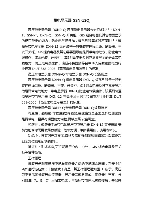
工作原理该装置是利用高压电场与传感器之间的电场耦合原理,在安全距离外进行感应式(非接触式)测量,其工作原理框如图1所示。
高压带电显示闭锁装置由传感器、显示器二部分组成,传感器共三支、分别对准“A、B、C”三相带电体,与高压带电体无直接接触,并保持一定的安全距离,它接受高压带电体电场信号,并传送给显示器进行比较判断;当被测设备或网络带电时,“A、B、C”三相指示灯亮,“操作”指示灯熄灭,且输出强制闭锁信号。
SCHOTTKY BARRIER DIODE LRB520S-商品说明书

DC
D=1/2 Sin(θ=180)
10
0.001 0.01 0.1
1
10 100 1000
TIME:t(s)
Rth-t CHARACTERISTICS
0
0
0.1
0.2
0.3
0.4
0.5
AVERAGE RECTIFIED FORWARD CURRENT:Io(A) Io-Pf CHARACTERISTICS
10
15
Ifsm 8.3ms 8.3ms 10 1cyc
5
5
Ifsm t
0
1
10
100
NUMBER OF CYCLES IFSM-CYCLE CHARACTERISTICS
0
0.1
1
10
100
TIME:t(ms)
IFSM-t CHARACTERISTICS
10000
Mounted on epoxy board
75 100 125
AMBIENT TEMPERATURE:Ta(℃) Derating Curve (Io-Ta)
0.5
0.4 DC
0.3 D=1/2
0.2
0A
Io
0V t
VR D=t/T
VR=20V
T Tj=125℃
0.1 Sin(θ=180)
0
0
25
50
75 100 125
CASE TEMPARATURE:Tc(℃) Derating Curve (Io-Tc)
LESHAN RADIO COMPANY, LTD. LRB520S-40T1G
FORWARD CURRENT:IF(mA)
鲁邦通 R5020 Lite 硬件说明书

R5020Lite 硬件说明书版本:V1.0.1日期:2023年02月27日监管和认证类型表1:方针2011/65/EU欧洲RoHS2.02011/65/EU 指令是欧盟议会及欧盟委员会于2011年7月1日发布的指令,系在电子电气设备中限制使用某些有害物质的强制性标准。
2012/19/EU欧洲WEEE 2012/19/EU 指令是欧盟议会及欧盟委员会于2012年7月24日发布的指令,系关于报废电子电气设备的标准。
2013/56/EU欧洲2013/56/EU 指令是欧盟官方公报于2013年12月10日发布的电池指令。
本产品使用的纽扣电池符合2013/56/EU 指令标准。
表2:中华人民共和国电子行业标准SJ/T 11363-2006中华人民共和国电子行业标准SJ/T 11363-2006《电子信息产品中有毒有害物质的限量要求》由中华人民共和国信息产业部于2006年11月6日发布,规定了电子信息产品中含有毒有害物质的最大允许浓度。
请参照表3的概述,SJ/T 11363-2006规定了产品零件中的有毒、有害物质或元素的浓度不能超过规定的限度。
SJ/T 11364-2014中华人民共和国电子行业标准SJ/T 11364-2014《电子电气产品有害物质限制使用标识要求》由中华人民共和国工业和信息化部于2014年7月9日发布,规定了电子电气产品有害物质、环保使用期限、可否回收利用的标识要求。
本标准适用于中华人民共和国境内销售的电子电气产品,亦可供电子电气产品的物流过程参照使用。
鲁邦通产品使用下方橙色标志:表示其警示属性,即产品中含有某些有害物质,图例中间的“10”指电子信息产品环保使用期限Environment-friendly Use Period(EFUP)*为10年,在环保使用期限内可以放心使用,超过环保使用期限之后则应该进入回收循环系统。
*电子信息产品环保使用期限是指在正常使用的条件上,电子信息产品中含有的有毒、有害物质或元素不会发生外泄或突变并导致对环境造成严重污染或对人身、财产造成严重损害的期限。
- 1、下载文档前请自行甄别文档内容的完整性,平台不提供额外的编辑、内容补充、找答案等附加服务。
- 2、"仅部分预览"的文档,不可在线预览部分如存在完整性等问题,可反馈申请退款(可完整预览的文档不适用该条件!)。
- 3、如文档侵犯您的权益,请联系客服反馈,我们会尽快为您处理(人工客服工作时间:9:00-18:30)。
76%
75%
72%
77%
79%
80%
80%
No load power consumption< 0.3W/240VAC Pass energy star level IV for full series
Meet EISA 2007 (Energy Independence and Security Act)2Class
power (without earth pin)
Protections: Short circuit / Overload / Over Voltage / Over temperature Fully enclosed plastic case
Approvals: UL / CUL / BSMI / CB / FCC Pass LPS for full series 2 years warranty
Universal AC input / Full range
pole USA plug SPECIFICATION
GS12U05-P1I GS12U07-P1I GS12U09-P1I GS12U12-P1I GS12U15-P1I GS12U18-P1I GS12U24-P1I ORDER NO.
SAFETY MODEL NO.DC VOLTAGE RATED CURRENT OUTPUT
SETUP, RISE, HOLD UP TIME VOLTAGE RANGE FREQUENCY RANGE
EFFICIENCY (Typ.)AC CURRENT
INPUT
INRUSH CURRENT (max.)LEAKAGE CURRENT (max.)SAFETY STANDARDS SAFETY &EMC WORKING TEMP.WORKING HUMIDITY
STORAGE TEMP., HUMIDITY TEMP. COEFFICIENT VIBRATION
MTBF DIMENSION OTHERS
NOTE
PLUG CABLE
OVERLOAD
OVER VOLTAGE
9V 7.5V 5V 12V 15V 18V 24V GS12U12GS12U15GS12U18GS12U241.33A 1.6A 2.0A 1.0A 0.8A 0.67A 0.5A CURRENT RANGE
0 ~ 1.33A 0 ~ 1.6A 0 ~ 2.0A 0 ~ 1.0A 0 ~ 0.8A 0 ~ 0.67A 0 ~ 0.5A RIPPLE & NOISE (max.)Note.290mVp-p 90mVp-p 75mVp-p
120mVp-p 150mVp-p 180mVp-p 200mVp-p VOLTAGE TOLERANCE Note.3LINE REGULATION Note.4LOAD REGULATION
Note.5
3.0% 3.0%1.0% 1.0% 1.0% 1.0% 1.0%5.0%
4.0%4.0%
5.0% 1.0% 1.0%4.0%4.0%
3.0%3.0%
3.0%3.0%
2.0%
2.0%
500ms, 20ms, 30ms/230VAC
at full load 500ms, 20ms, 10ms/115VAC 90 ~ 264VAC 135 ~ 370VDC 47 ~ 63Hz 0.31A / 230VAC A / 115VAC 0.16COLD START 25A / 115VAC 45A / 230VAC
0.25mA / 240VAC
>105% rated output power
115% ~ 135%
UL60950-1, CSA22.2, BSMI CNS14336 approved WITHSTAND VOLTAGE
ISOLATION RESISTANCE I/P-O/P:3KVAC
I/P-O/P:/ 25
/ 70% RH
100M Ohms / 500VDC 1414.6Khrs min. MIL-HDBK-217F (25)0 ~ +50
(Refer to output load derating curve)
20% ~ 90% RH non-condensing
-20 ~ +85, 10 ~ 95% RH
0.03% /(0 ~ 40)
10 ~ 500Hz, 2G 10min./1cycle, period for 60min.each along X,Y, Z axes 65*47*26.5mm (L*W*H)
1.All parameters are specified at 115VAC input, rated load, 2570% RH Ambient.
2.Ripple & noise are measured at 20MHz by using a 12" twisted pair terminated with a 0.1uf & 47uf capacitor.
3.Tolerance: includes set up tolerance, line regulation, load regulation.
4.Line regulation is measured from low line to high line at rated load.
5.Load regulation is measured from 10% to 100% rated load.
6.The over temperature protection (OTP) is the built-in function of the control IC (U1). The activating level described above is based on the specification provided by the IC manufacturer.
CONNECTOR GS12U09GS12U07GS12U05RATED POWER
12W 12W 12W 12W 10W 12.06W 12W Standard type P1I: 2.1
* 5.5
* 9.5mm turning fork type, center positive for stock ; Other type available by customer requested
Standard type UL1185 6ft (4FT only for 5V output) for stock ; Other type available by customer requested
Features :
Compliance to FCC part15 class B, EN55022, EN61204-3 class B, BSMI CNS13438
Compliance to EN61000-3-2,3
Compliance to EN61000-4-2,3,4,5,6,8,11, ENV50204, EN61204-3, l criteria A ight industry level,HARMONIC CURRENT EMS IMMUNITY EMI CONDUCTION & RADIATION
Protection type : Hiccup mode, recovers automatically after fault condition is removed Protection type : Clamp by zener diode
ENVIRONMENT PROTECTION U1Tj 140typically (U1) Detect on main control IC
Protection type : Shut down o/p voltage, recovers automatically after temperature goes down OVER TEMPERATURE Note.6File Name:GS12U-SPEC 2008-05-06
PACKING 0.15Kg ; 100pcs / 16Kg / CARTON
Mechanical Specification
File Name:GS12U-SPEC 2008-05-06
UL1185 18AWG 123050mm for 5V UL1185 18AWG 183050mm for others
26.51
171651
471
9.50.5mm
ID 2.1 x OD 5.5
C"+"
6.30.3
Derating Curve
Static Characteristics(24V)
Unit:mm
Plug Assignment
Standard plug: P1I (option)
P/N
CENTER
OUTPUT
+
P1I
12.70.4
1.50.2
INPUT VOLTAGE(VAC)60Hz
Ta ()L O A D (%)
010********
100
50509070120110160140200180240220264
O U T P U T V O L T A G E (V )
O U T P U T R I P P L E (m V p -p )
Ta=25
2825032
30024200201501610012508
25
3010mm。