EV(DV)300说明书(V1.1)
三星DV100说明书

拍摄文字、昆虫或花卉相片
•
模式 > 文本 34
• 微距 51
调整曝光(亮度)
• ISO 速度(调整感光度) 50 • EV(调整曝光) 58 • ACB(根据明亮背景补偿拍摄对象) 59 • 测光 59 • AEB(使用不同的曝光为同一场景拍摄三张相片)
62
应用不同效果
•
模式 > 魔框 34
• 智能滤镜效果 63
• 图像调整(调整饱和度、鲜明度或对比度) 66
减少相机抖动 • 数字图像稳定 (DIS) 28
• 在智能相册中按类别查看 文件 70
• 按缩略图查看文件 71 • 删除存储卡中的所有
文件 72
• 以幻灯片播放形式查看 文件整声音和音量 92 • 调整显示的亮度 93 • 更改显示语言 94 • 设置日期和时间 94 • 格式化存储卡 94 • 疑难解答 106
当光源位于拍摄对象背后时,或者当明暗区域之间形成强烈对比时,拍摄对象可能会变淡。 • 避免正对日光进行拍摄。 • 在 模式中选择 逆光。(请参阅第 34 页) • 请将闪光灯选项设置为 强制闪光。(请参阅第 49 页) • 设置“自动对比度平衡”(ACB) 选项。(请参阅第 59 页) • 调整曝光。 (请参阅第 58 页) • 如果明亮拍摄对象位于对焦区域中央,请将测光选项设置为 点测光。(请参阅第 59 页)
背景
合成 拍摄对象
标准曝光
6
过度曝光(太亮)
拍摄的常见问题
通过设置拍摄选项,可以解决大部分问题。
拍摄对象眼睛为 红眼。
这是因相机闪光灯的反射而造成。 • 请将闪光灯选项设置为 消减红眼或 • 如果已拍摄相片,则在编辑菜单中选择
红眼消除。(请参阅第 49 页) 红眼消除。(请参阅第 79 页)
EP3001评估板手册说明书
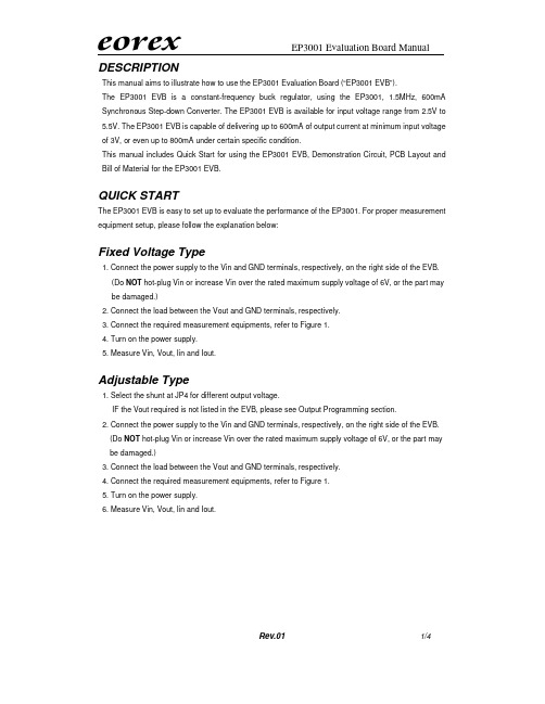
1/4DESCRIPTIONThis manual aims to illustrate how to use the EP3001 Evaluation Board (“EP3001 EVB”).The EP3001 EVB is a constant-frequency buck regulator, using the EP3001, 1.5MHz, 600mA Synchronous Step-down Converter. The EP3001 EVB is available for input voltage range from 2.5V to 5.5V. The EP3001 EVB is capable of delivering up to 600mA of output current at minimum input voltage of 3V, or even up to 800mA under certain specific condition.This manual includes Quick Start for using the EP3001 EVB, Demonstration Circuit, PCB Layout and Bill of Material for the EP3001 EVB.QUICK STARTThe EP3001 EVB is easy to set up to evaluate the performance of the EP3001. For proper measurement equipment setup, please follow the explanation below:Fixed Voltage Type1. Connect the power supply to the Vin and GND terminals, respectively, on the right side of the EVB. (Do NOT hot-plug Vin or increase Vin over the rated maximum supply voltage of 6V, or the part may be damaged.)2. Connect the load between the Vout and GND terminals, respectively.3. Connect the required measurement equipments, refer to Figure 1.4. Turn on the power supply.5. Measure Vin, Vout, Iin and Iout.Adjustable Type1. Select the shunt at JP4 for different output voltage.IF the Vout required is not listed in the EVB, please see Output Programming section. 2. Connect the power supply to the Vin and GND terminals, respectively, on the right side of the EVB. (Do NOT hot-plug Vin or increase Vin over the rated maximum supply voltage of 6V, or the part may be damaged.)3. Connect the load between the Vout and GND terminals, respectively.4. Connect the required measurement equipments, refer to Figure 1.5. Turn on the power supply.6. Measure Vin, Vout, Iin and Iout.2/4Jump Setting1. Default setting of JP1 is RUN, so as to enable the EP3001. If Shutdown condition is required, please turn off the power supply and switch JP1 to SHDN. Then power on to test the Shutdown condition. Do NOT keep JP1 floating at any time.2. JP3 is for voltage option only. FIXED is for fixed voltage option with the marking of “A2YW”, “A3YW”, “A4YW” and “C4YW”. ADJ is for adjustable voltage option with the marking of “A1YW”. Do NOT change JP3 at any time.3. JP4 is for output voltage selection for adjustable type. When AUX is selected, please see the following section.Output ProgrammingThe output programming resistors for adjustable type are listed in Table 1. If AUX with JP4 is selected, please put on R2F according to the following equation:+=1216.0R R V V out Table 1 Output Programming ResistorVout (V) R1 (K Ω) R2 (K Ω) 1.2 60 R2A = 60 1.5 60 R2B =90 1.8 60 R2C = 120 2.5 60 R2D =190 3.1 60 R2=250 3.3 60 R2E = 270 AUX60 R2F = FunctionFigure 1 EP3001 Evaluation Board Diagram3/4DEMONSTRATION CIRCUIT4/4BILL OF MATERIALItem Qty Ref. Part Description Manufacture/Part No.Note 11 C1CAP.,X5R Ceramic, 4.7uF,6.3V,20%,0805 MURATA,GRM31CR71A475KA01L2 1 C2CAP.,X5R,10Uf,6.3V,20%,1206 MURATA,GRM31CR70J106KA01L3 1 C3 CAP.,NPO, 22Pf,25V,20%,0603 GARRETT,0603CG220J9B204 1 L1 INDUCTOR,2.2uH,20% MURATA,LQH43CN2R2M03L 51 R1RES.,CHIP,60K,1/16W, 1%,0603AAC 6 1 R2ARES.,CHIP,60K,1/16W, 1%,0603AAC7 1 R2BRES.,CHIP,90K,1/16W, 5%,0603AAC8 1 R2CRES.,CHIP,120K,1/16W, 5%,0603AAC9 1 R2DRES.,CHIP,250K,1/16W, 5%,0603AAC10 1 R2ERES.,CHIP,270K,1/16W, 5%,0603AAC11 1U1IC,EP3001,SOT23-5A1YW, A2YW, A3YW, A4YW, C4YW。
变频器品牌型号台账

变频器品牌型号台账部分台账目录:1.台安(TAIAN)变频器说明书E2 N2 V2 SV300 N310 S310 EV300 K1/N1 K200/K400 9300JS E2-EN 2.台达(DELTA)变频器说明书VFD-A VFD-B VFD-E VFD-F VFD-G VFD-L VFD-MVFD-S VFD-V VFD-VE VFD-EL VFD-B/P VFD-VL3.英威腾(INVT)变频器说明书G9/P9/GS/GL CHE CHF CHV CHV110 CHV160 CHV1804.汇菱(HUILING)变频器说明书 H30005.信捷(XINJE)变频器说明书 V5/F56.凯迪华能变频器说明书 CD20007.酷马(QMA)变频器说明书 Q5000 Q7000 Q90008.黎升同步控制器说明书 SAD240 SAD280 SAD280i9.三品(SANPIN)变频器说明书 SKJ SPRQ-33310.能士(NSA)变频器说明书 NSA20 NSA8011.台凌(TAILING)变频器说明书 TL80 TL100 TL100H12.力普变频器说明书 LP10013.安普(AMPLE)变频器说明书 AMP100014.誉强(YUQIANG)变频器说明书YQ3000-M YQ3000-A YQ3000-G YQ3000-A7(上) A7(中) A7(下)15.格立特(GREAT)变频器说明书VF10 VF11 VF15 VC300 VC3100 VC320016.RICH(利佳/艾瑞克)变频器说明书EI-MINI EI-450EI-450M EI-500EI-550EI-600EI-700EI-7001 EI-8001 EI Super N17.汇川(INOVANCE)变频器说明书MD021 MD280 MD300 MD300A MD320 MD33018.远川(YCDZ)变频器说明书YC-G YC-P TE580 软启动器19.紫日(CHZIRI)变频器说明书ZVF7 ZVF9 ZVF9V ZVF11 软启动20.森兰(SENLAN)变频器说明书SB12 SB40 SB50 SB60/61 SB60+/61+ SB61Z SB61Z+ SB70 SB80 SB100 SB200 BT12 BT4021.安邦信(AMBITION)变频器说明书G7/P9 G9/P9 V11 G11 E11 Z9/Z11 HVI22.普传(POWTRAN)变频器说明书168 PI97G PI7000/7100 PI7600/7800 PI766023.日业(SUNYE)变频器说明书。
变频器说明书大全
变频器说明书大全本文提供多年收藏整理的变频器说明书,全部为高清PDF版本。
如果需要,请发送邮件到XXX索取。
以下是说明书部分目录:1.台安(TAIAN)变频器说明书:包括E2N2V2SV300N310S310EV300K1/N1K200/KxxxxxxxJSE2-EN2.2.台达(DELTA)变频器说明书:包括VFD-AVFD-BVFD-EVFD-FVFD-GVFD-LVFD-M、VFD-SVFD-VVFD-VEVFD-ELVFD-B/PVFD-VL。
3.英威腾(INVT)变频器说明书:包括G9/P9/GS/GLCHECHFCHVCHV110CHV160CHV180.4.XXX(HUILING)变频器说明书:包括H3000.5.信捷(XINJE)变频器说明书:包括V5/F5.6.凯迪华能变频器说明书:包括CD2000.7.酷马(QMA)变频器说明书:包括Q5000Q7000Q9000.8.黎升同步控制器说明书:包括SAD240、SAD280、SAD280i。
9.三品(SANPIN)变频器说明书:包括SKJSPRQ-333.10.能士(XXX)变频器说明书:包括NSA20NSA80.11.台凌(TAILING)变频器说明书:包括TL80TL100TL100H。
12.力普变频器说明书:包括LP100.13.XXX(AMPLE)变频器说明书:包括AMP1000.14.誉强(YUQIANG)变频器说明书:包括YQ3000-MYQ3000-AYQ3000-GYQ3000-A7(上)A7(中)。
A7(下)。
15.格立特(GREAT)变频器说明书:包括VF10VF11VF15VC300VC3100VC3200.16.RICH(XXX)变频器说明书:包括EI-MINIEI-450EI-450MEI-500EI-550EI-600EI-700EI-xxxxxxxxEI Super N、EI。
17.汇川(INOVANCE)变频器说明书:包括MD021 MD280 MD300MD300AMD320MD330.18.XXX(YCDZ)变频器说明书:包括YC-GYC-PTE580软启动器。
EP300系列产品使用说明书 ver 1.22-2

PON光功率计使用说明书Ver 1.22天津市德力电子仪器有限公司地址: 天津市高新技术产业园区(环外)海泰创新三路8号(300392)服务电话:022 2763 1088传真:022 2764 5002网址:电子邮件:deviser@保修仪器售出后保修3年,3年保修期到期之前,可以购买延长保修期服务。
用户的职责是:按照说明书来使用这台仪器,假如要维修,就把它送往本公司或指定代理维修站。
一般说来于保修期内,一切非人为使用不当的故障,当由德力公司免费维修。
用户需支付将产品退回至维修部门的运费和保险费,而将维修好的产品交付给用户的费用则由德力公司或指定代理维修站支付。
本公司为本产品设计的软件和硬件正确安装到仪器上后,仪器将执行它的编程指令。
但本公司不保证仪器的各种操作不间断或不出现错误信息。
保修只限于仪器,并不涉及使用不当而导致其它设备、生命及财产的损失。
保修限制保修不包括以下各项:①对因使用不当或有害清洁造成光探测器或光接口损坏而进行的更换,需要进行收费。
②随机赠送的电池或电源适配器。
③由于机械外力(撞击、跌落等)造成面板、开关、装置及机壳的变形损坏并涉及到内部器件的故障。
④擅自拆开仪器试图修理的。
⑤用户提货时,应当场查验,如遇仪器损毁,请向货运公司或部门交涉。
只有收货人(接收仪器的个人与单位)才有权就运输损毁向承运者提出赔偿要求。
开箱请小心开箱,并注意将全部附件放在一个地方,以防遗失。
我们建议最好保存原包装箱和包装材料,以备将来搬运时使用。
注意只有经过维修培训的人员才能维护本仪器。
为了避免损坏,未经过培训人员不应进行仪器的维护修理。
本说明书仅对随机产品有效,其中所载技术规格和操作方法可能改变,恕不另行通告。
使用一段时间后,如有何需要,请向生产商查询。
仪器断电后,内部电容仍可能带有电荷。
本公司保留所有版权,未经书面同意不得复制、改编或翻译。
目录一、安全性 (1)二、一般性说明 ................... 错误!未定义书签。
Everfocus EHD300N 粗犷型彩色固定摄像机操作说明书

EVERFOCUS1/3” Color Rugged Dome CameraOperation InstructionsModel No. EHD300NPlease read this manual first for correct installation and operation. This manual should be retained for future reference. The information in this manual was current when published. The manufacturer reserves the right to revise and improve its products. All specifications are therefore subject to change without notice.PRECAUTIONS1. Do not install the camera near electric or magnetic fields.Install the camera away from TV, radio transmitter, magnet, electric motor, transformer,audio speakers since the magnetic fields generate from above devices will distort the video images.2. Never disassemble the camera nor put impurities in it.Disassembly or impurities may result in trouble or fire.3. Never face the camera toward the sun.Direct sunlight or severe ray may cause fatal damage to sensor and internal circuit.4. Keep the power cord away from water and liquid.Touching the wet power cord may result in electric shock.5. Never install the camera in areas exposed to water, oil or gas.Water, oil or gas may result in failure, electric shock or fire.6. CleaningDo not touch the surface of sensor by hand directly. Use a soft cloth to remove the dirt from the camera body. Use lens tissue or a cotton swab and ethanol to clean the sensor and the camera lens.7. Do not operate the camera beyond the specified temperature, humidity orpower source ratings.Use the camera at temperatures within –10℃~ 50℃/14℉ ~ 122℉and humidity between 20%~ 80%. The input power source is 12VDC/24V AC.PREFACEThe most technically advanced EHD series are the newest vandal-resistant Color Rugged Dome Camera from EverFocus Electronics. The Color Rugged Dome Camera can withstanda blow from a 10-pound sledgehammer and has a built-in heater that allows for operation inlow temperatures. It is perfect for all high-profile crime-prone applications such as building entrances, retail stores, and shopping malls. EHD series are unquestionably one of theworld's toughest cameras and is your best choice for vandal resistance.FEATURESz1/3” SONY Super HAD color CCD pick up device for more than 520 TV lines ofhorizontal resolutionz Low light sensitivity of 0.4 lux/F=1.2 is achieved by using 1/3” SONY Super HADinterline transfer color CCDz The electronic shutter and AGC allow the camera to be used in environment withvarying light levelsz12VDC/24V AC switches automatically power supplyz S/N Ratio reaches 48 dB or morez Built-in Vari-focal lensz Flickerless, Mirror, AGC and BLC ON/OFF switchablez With manual Pan/Tilt mechanismz Rugged dome designed for vandal proofz Rugged Dome designed with 3-axis which provides the best installation for ceilingand wall mountz IP66 weatherproofINSTALLATION1. Loosen the 4 fix screws on the housing cover by using the attached wrench (Figure 1). Please pay attention not to damage the lens.2. Remove the camera.To remove the camera, first unplug the wire connection on the back of the camera. Then loosen the 2 locking screws on the camera base, push the camera base to the right (toward heater direction, as shown in Figure 2), remove the camera from the mounting base. Reinstall the camera and the cable while the base mounting is completed.Figure 1Figure 2Locking ScrewsVari-Focal Lens3.Mounting the base.Side conduit entryConduit plug setscrew Back conduit entryMounting Setscrew Mounting SetscrewMounting SetscrewMounting SetscrewFigure 3Attach the base to the wall or ceiling, fix the base by the 4 setscrews attached in the accessory pack. Please make sure if the mounting is strengthened enough tosupport it, if not, please reinforce the mounting according to the environment.Note: The diameter of the screw hole isψ4.7mm.Caution: To prevent moisture leaking into the housing, apply an appropriate gasket or sealant around the conduit connection.4. Wire ConnectionThe camera comes with a conduit plug pre-installed in the PF 1/2 conduit entry on the side. The screw can be removed andinstalled in the back conduit entry. Loosen the conduit plug setscrew (as shown in Figure 4) before removing the conduit plug.Side conduit entry (PF1/2)Conduit plugBack conduit entry (PF1/2)Figure 4Termination BoardConnect the power supply cable (12VDC/24V AC), video output and alarm output to the proper connectors shown as Figure 5.The V. Phase adjustment screw is located on the termination board. The vertical phase may require adjustment to synchronize the vertical phase of the camera with other camera in the system when it is to be used in the line-lock sync mode. Make the adjustment when the vertical phase of the camera does not match with other cameras.5. View Angle AdjustmentThe camera can be rotated 360° horizontally, 140° vertically and 60° 3’rd axis view angles (as shown in Figure 6). Adjust the proper camera view angle as needed. If a vari-focal lens is used, you may adjust the focus and zoom of the lens to bring the object in focus. Be sure to loosen the locking screws on the lens before you make adjustment.VideoAlarm COMMicro Switch for Alarm trigger GNDAlarm NOAlarm NC Power In (+)V . Phase Adjustment VRFigure 5Power In (-)140°36060°Figure 6DIP SWITCH FUNCTION¾ BLC (Back Light Compensation)When BLC is turned on, the AGC, FL and IRIS operating point is determined by averaging over the center area instead of entire field-of-view, so that a dimly-lit foreground object at center area can be clearly distinguished from brightly-lit backgrounds. BLC should not be used unless it is needed to compensate for back-light.The default setting is OFF. For Auto-Iris lens model, the brightness can also be adjusted via the Iris level control VR.¾ AGC (Automatic Gain Control)AGC ON: The sensitivity increases automatically when light is low.AGC OFF: A-low-noise picture is obtained under a low light condition.The default setting is ON.¾FL (Flickerless)When picture flicker fiercely, turn FL on, then the camera will stabilize the speed of electronic shutter at 1/100(S)(NTSC) or 1/120(S)(PAL) automatically, and reduce the flicker immediately. The default setting is OFF.¾IRIS Level Control (For Vari-Focal Lens Model)Brightness Level can be adjusted from the IRIS level VR while using the direct drive lens. •Turn counterclockwise to L to get darker picture.•Turn clockwise to H to get brighter picture.¾Electronic Shutter (For Fixed Lens Model) ES ON: The camera continuously adjusts the shutter speed from 1/60 (NTSC), 1/50 (PAL) second to 1/100,000 second according to the luminance conditions of the scene.ES OFF: The shutter speed is fixed at 1/60 (NTSC),1/50 (PAL) second.Set ES OFF, when auto iris lens is used or flicker is observed under a very bright fluorescent lamp. Otherwise, turn ES on for optimum performance.SIMPLE INSTRUCTIONS FOR THE DESICCANT PACKDue to the camera lens blurred from the humidity inside the camera.The desiccant pack absorbs the humidity; please refer to the easy instruction as follows: 1.Adjust all settings first and place the desiccant pack on the horizontal rod, then bend thehorizontal rod and fix it.2.Install the outer cover and tighten the screws.Installation steps for the camera:Step 1Step 2Step 3Desiccant packHorizontal rodBend the horizontal rod and fix the desiccant packInstall the outer cover and tighten the screwsSPECIFICATIONSPickup Device 1/3'' SONY Super HAD CCD Video Format NTSC or PALScanning System NTSC: 525 TV lines, 60 fields/sec. PAL: 625 TV lines, 50 fields/sec.Picture Elements 768 x 494(NTSC) ; 752 x 582(PAL) Horizontal Resolution 520TVLSensitivity 0.4Lux/F=1.2S/N Ratio Over 48dB (AGC off)Electronic Shutter 1/50(1/60)~1/100,000Lens Type Vari-focal lens, Auto Irisf=2.9~10mm, F=1.2f=9~22mm, F=1.6*Lens models and availability vary in different regionsAuto Gain Control ON/OFF Switch Flickerless ON/OFF Switch Back Light Comp. ON/OFF Switch Auto White Balance YesGamma Correction 0.45Video Output 2 video outputsBNC 1.0Vp-p, 75ohmAdditional testing video output 1.0Vp-p, 75ohmSync. Mode Internal sync Weatherproof IP66Vandal Resistant YesPower Source 12VDC/24VACPower Consumption 24VAC: 1.5W max. 12VDC: 2W max.Dimensions 130mm(W) x 98.8mm(H) x 130mm(D);5.1"(W) x 3.87"(H) x 5.1"(D)Weight 0.8kg ; 1.8lbsOperating Temperature -10°C~50°C ; 14°F~122°F (20%~80% Humidity) Certifications FCC/CECONTENT LISTStandard Accessories1.Camera Unit2.Operation Instruction (this document)3.Accessory Pack4.Waterproof Connector5.Power & Video CableOptional Accessory1. Wall Mount Bracket (BA-EHD)EverFocus Electronics Corp.Head Office:12F, No.79 Sec. 1 Shin-Tai Wu Road, Hsi-Chih, Taipei, Taiwan TEL: +886-2-26982334 FAX: +886-2-26982380 USA L.A. Office:1801 Highland Ave. Unit A Duarte, CA 91010, U.S.A. TEL: +1-626-844-8888 FAX: +1-626-844-8838 USA N.Y. Office:415 Oser Avenue Unit S Hauppauge, NY 11788 TEL: 631-436-5070 FAX: 631-436-5027 P/N: MEHDG01110_Ver.AEurope Office:Albert-Einstein-Strasse 1 D-46446 Emmerich, Germany TEL: 49-2822-9394-0 www.everfocus.deChina Office:Room 609, Technology Trade Building, Shangdi Information Industry Base, Haidian District, Beijing,China 10085 TEL: +86-10-62973336/37/38/39 FAX: +86-10-62971423 Japan Office:1809 WBG MARIBU East 18F, 2-6 Nakase.Mihama-ku. Chiba city 261-7118, Japan TEL: +81-43-212-8188 FAX: +81-43-297-0081 。
变频器品牌型号台账

变频器品牌型号台账部分台账目录:1.台安(TAIAN)变频器说明书E2 N2 V2 SV300N310 S310 EV300K1/N1 K200/K400 9300JS E2-EN 2.台达(DELTA)变频器说明书VFD-A VFD-B VFD-E VFD-F VFD-G VFD-L VFD-MVFD-S VFD-V VFD-VE VFD-EL VFD-B/P VFD-VL3.英威腾(INVT)变频器说明书G9/P9/GS/GL CHE CHF CHV CHV110CHV160CHV1804.汇菱(HUILIN G)变频器说明书 H30005.信捷(XINJE)变频器说明书 V5/F56.凯迪华能变频器说明书CD20007.酷马(QMA)变频器说明书 Q5000Q7000Q90008.黎升同步控制器说明书SAD240 SAD280 SAD280i9.三品(SANPIN)变频器说明书 SKJ SPRQ-33310.能士(NSA)变频器说明书 NSA20NSA8011.台凌(TAILIN G)变频器说明书 TL80 TL100TL100H12.力普变频器说明书 LP10013.安普(AMPLE)变频器说明书 AMP100014.誉强(YUQIAN G)变频器说明书YQ3000-M YQ3000-A YQ3000-G YQ3000-A7(上) A7(中) A7(下)15.格立特(GREAT)变频器说明书VF10 VF11 VF15 VC300VC3100VC320016.RICH(利佳/艾瑞克)变频器说明书EI-MINI EI-450EI-450M EI-500EI-550EI-600EI-700EI-7001 EI-8001 EI SuperN17.汇川(INOVAN CE)变频器说明书MD021MD280MD300MD300A MD320MD33018.远川(YCDZ)变频器说明书YC-G YC-P TE580软启动器19.紫日(CHZIRI)变频器说明书ZVF7 ZVF9 ZVF9VZVF11软启动20.森兰(SENLAN)变频器说明书SB12SB40SB50SB60/61SB60+/61+SB61ZSB61Z+ SB70SB80 SB100SB200BT12 BT4021.安邦信(AMBITI ON)变频器说明书G7/P9 G9/P9 V11 G11 E11 Z9/Z11 HVI22.普传(POWTRA N)变频器说明书168 PI97GPI7000/7100 PI7600/7800 PI766023.日业(SUNYE)变频器说明书。
JVC KA-DV300U 说明书

KA-DV300U /StreamproducerQuick-StartFor KA-DV300 firmwareversion 104 andStreamproducer 2.0JVC wants you to get the most out of your GY-DV300 with the KA-DV300 Network Pack. Ifyou have any questions, concerns orproblems, please feel free to contact ourNetwork Product Specialist at: *************Supported Accessory Cards:•Operating Voltage: 3.3 VDC•Max. Current: 300 mA @ 5VAs of October 2002, the KA-DV300 supports the followingaccessory cards:•Wired LAN:o SocketCommunications12of the GY-DV300 below the battery compartment.4. Rotate the KA-DV300 upward toward the GY-DV300 until apositive ‘click’ is heard and felt.5. To remove the KA-DV300 Network Pack, press the releasebutton on the front of the pack and pull away from thecamera.Wired Connections, Single Camera toSingle ComputerDHCP:OFFDHCP:OFFIP Address: 192.168.100.101 IP Address: 192.168.100.102Netmask: 255.255.255.0 Netmask: 255.255.255.0Both IP addresses must be within the same network groupand have the same subnet mask, as shown by the shadingabove. In this example, the Network Group is 192.168.100.When connecting directly from the camera to a computer,operation is assured if the following conditions are met:•DHCP should be OFF.•If DHCP is off, the IP address of the camera and thecomputer must be unique, but in the same NetworkGroup.•The Netmask of both the camera and computermust be the same.• A CAT-5 crossover cable is used between thecamera and computer if no switch or hub is present.•Under most conditions, the computer LAN cardshould be set for no proxy server. Please refer tothe KA-DV300 Users Guide for informationregarding this setting if troubles are encountered.Wireless Connections, Single Camerato Single ComputerIn a similar manner to the wired connection, when connectingdirectly from the camera to a computer using a wireless linkwithout an access point, operation is assured if the followingconditions are met:•DHCP must be OFF.•The IP address of the camera and the computermust be unique, but in the same Network Group.•The Netmask of both the camera and computermust be the same•set the WLAN AD HOC MODE to ON.•The WLAN ESS ID on both the KA-DV300 and thecomputer must be the same. The camera defaultESS ID is ‘wireless-lan’.•The KA-DV300 and the computer must be set touse the same channel (WLAN CH).•Under most conditions, the computer LAN cardshould be set for no proxy server. Please refer tothe KA-DV300 Users Guide ‘Setting a Proxy Server’for information regarding this setting if troubles areencountered.HookInstalling StreamproducerIf your computer meets the minimum requirements discussed on Page 5 of the Streamproducer Users Guide and does not have a previous version of Streamproducer installed (if it does, follow the directions on Page 7 of the Streamproducer Users Guide for removing it) you can proceed with the automatic installation. 1.Insert the Streamproducer CD ROM into your computers CD drive. If Setup is not started automatically, click on ‘Start’ and then ‘Run’. Run the file ‘Startup.exe’ from the CD-ROM. 2.From the opening window, you choose whether to continue with an English or Japanese installation. For this discussion, English was selected.3. The next windowenables you to select what portions to install. Click “InstallStreamproducer:4. The installationwill continue automatically. When asked, werecommend installing the software into the default folder, as shown below. 5.You will be given an opportunity to select which models of JVC cameras you will be connecting to. Even if you only have one camera type, we recommend installing the software for all camera types, as shown here:6.All files required for use are installed in a single step, including the required CODECs and Streamcapture, the plug-in for using Internet Explorer. When the installationcompletes, you will have to reboot your computer, which can be done automatically by selecting this option and clicking “Finish”.Connecting with StreamproducerConnecting to the camera with JVC’s Streamproducer supports the following features:• Real-time viewing of up to four cameras or .asf files, with audio.• Remote control and setup of all connected cameras and network packs.• Capturing (saving to PC disk drive) the output from any connected camera.• Connections to multiple cameras using a single instance of Streamproducer.• Instant switching between cameras and files when streaming.• Publishing point for a media server. •Stream to up to 10 clients.The following example shows how to connect to a single camera using Streamproducer:1. Open Streamproducer.2.In and one of the viewable windows, click the ‘Camera’ icon.3.In the IP address window, enter the address of the desired camera, as shown here, click ‘OK’.4.Enter the camera name. Although we recommend that it does, this name does not have to match the name assigned to the camera in the cameras menu. The name entered here is used to create a folder onthe PC where captured scene files are stored.5.Click ‘OK’. The camera output will appear in the window in about two seconds.Please refer to the Streamproducer Users Guide for instructions on streaming using StreamproducerConnecting with a Web BrowserConnecting to the camera with A Web Browser supports the following features:• Real-time viewing of camera output, with audio. • Remote control and setup of camera and network pack.• Capturing (saving to PC disk drive) camera output • Connections to multiple cameras using multiple instances of the Web browser (each instance can connect to only one camera)• Publishing point for a media server. •Stream to a single client.NOTE: Installation of Streamproducer is required before a WebBrowser connection can be established.The following example shows how to connect to the camera using Microsoft Internet Explorer: 1. Open Internet Explorer 2.Enter the cameras IP address in the address bar as shownhere3. Press ‘Enter’ or click ‘Go’4.If a valid connection between your computer and the GY-DV300/KA-DV300 exists, you should see the camera login screen, shown here. Note that this screen will not be shown if you have previously logged into the camera and selected the ‘Remember my Password’ option. 5.Once a user name andpassword have been entered, theNETWORK SETUP screen, shown here, will be visible.6.To view or cast the camera output, click ‘STREAMCAPTURE’. The view window, shown at right, will open.Please refer to the Streamproducer Users Guide for instructions on streaming using StreamcaptureDetermining the Casting URLTo determine the casting URL (the address that clients use to view the stream) when usingStreamproducer , click on the‘CONNECTIONS’ tab. Any URL shown is valid.When connection, a client must use both the URL and port as shown in the window.To determine the casting URL (the address that clients use to view the stream) when using Streamcapture with Internet Explorer , from the Streamcapture window, shown previously, click ‘PROP’, then click ‘CAST’. Any URL listed is valid. When connection, a client must use both the URL and port as shown in the window.。
- 1、下载文档前请自行甄别文档内容的完整性,平台不提供额外的编辑、内容补充、找答案等附加服务。
- 2、"仅部分预览"的文档,不可在线预览部分如存在完整性等问题,可反馈申请退款(可完整预览的文档不适用该条件!)。
- 3、如文档侵犯您的权益,请联系客服反馈,我们会尽快为您处理(人工客服工作时间:9:00-18:30)。
EV/DV300 Series Power MeterUser’s Manual用户手册AccuenergyYour Power and Automation PartnerEV/DV Series CopyRight© 2005 v1.1 Accuenergy Technology Co., Ltd版权所有,未经本公司之书面许可,此手册中任何段落、章节内容均不得被摘抄、拷贝或以任何形式复制与传播,否则一切后果由违者承担。
本公司保留一切法律权利。
订货前,请垂询本公司或当地代理商以获悉本产品的最新规格。
EV/DV Series在试图安装、操作或维护此设备之前,请仔细阅读本手册。
以下出现在本手册中或在设备上的特殊信息用来警示潜在的危险或用于阐释和规定操作规程,请注意。
附有这种安全标志示意周围存在着电力危险,假若未遵照一定的指令将会导致人身伤害。
Array这是安全警告标志,用来警告你潜在人身伤害的危险,遵照此标志后的所有安全信息,避免可能的伤害或死亡。
此标志指示临近于危险位置,如不加以避免将导致死亡或严重伤害。
该标志起着重提示作用,避免由于操作不慎而导致仪表不能正常工作甚至损坏仪表或对人身造成伤害。
在维护和检修之前,设备必须断电并接地。
维护工作只能由有资质的人员执行。
不是一本适用于未受训者的操作手册,在其正常使用范围之外所引起的问题,本公司盖不负责。
EV/DV Series目录版权页´´´´´´´´´´´´´´´´´´´´´´´´´´´´´´´´´´´´´´´´´´´´´´´´´´´´´´´´´´´´´´´´´´´´´´´´´´´´´´´´´´´´´´´´´´´´´´´´´´´´´´´´´´´´´´´´´´´´´´´´´´´´´´´´´´´´´´´´´´´´´´´´´´´´´´´´´´´´´´´´´´´´´´Ⅰ安全说明Array目录第一章简介1.1 EV/DV300系列产品的特点1.2 EV/DV300系列产品的应用领域1.3 EV/DV300系列产品分类第二章安装2.1 EV/DV300系列产品的外观尺寸2.2 EV/DV300系列产品的安装方法2.3 EV/DV300系列产品的接线方法2.4 EV/DV300系列产品的扩展I/O第三章基本操作与使用3.1 EV/DV300系列产品的显示屏与操作按键3.2 EV/DV300系列产品的测量数据显示操作EV/DV Series 3.3 EV/DV300系列产品的参数设定´´´´´´´´´´´´´´´´´´´´´´´´´´´´´´´´´´´´´´´´´´´´´´´´´´´´´´´´´´´´´´´´´´´´´´´´´´´´´´´´´´´´´´´´´´´´´´´´´34第四章通讯´´´´´´´´´´´´´´´´´´´´´´´´´´´´´´´´´´´´´´´´´´´´´´´´´´´´´´´´´´´´´´´´´´´´´´´´´´´´´´´´´´´´´´´´´´´´´´´´´´´´´´´´´´´´´´´´´´´´´´´´´´´´´´´´´´´´´´´´´´´´´´´´´´´´´´´´´´´´´´´´´464.1 MODBUS协议简述´´´´´´´´´´´´´´´´´´´´´´´´´´´´´´´´´´´´´´´´´´´´´´´´´´´´´´´´´´´´´´´´´´´´´´´´´´´´´´´´´´´´´´´´´´´´´´´´´´´´´´´´´´´´´´´´´´´´´´´´´´´´´´´464.2 通讯应用格式说明´´´´´´´´´´´´´´´´´´´´´´´´´´´´´´´´´´´´´´´´´´´´´´´´´´´´´´´´´´´´´´´´´´´´´´´´´´´´´´´´´´´´´´´´´´´´´´´´´´´´´´´´´´´´´´´´´´´´´´´´´´´´´´´´´´514.3 EV300系列产品通讯地址表´´´´´´´´´´´´´´´´´´´´´´´´´´´´´´´´´´´´´´´´´´´´´´´´´´´´´´´´´´´´´´´´´´´´´´´´´´´´´´´´´´´´´´´´´´´´´´´´´´´´´´´´´´´´59 Array 66附录 A 技术参数与规格´´´´´´´´´´´´´´´´´´´´´´´´´´´´´´´´´´´´´´´´´´´´´´´´´´´´´´´´´´´´´´´´´´´´´´´´´´´´´´´´´´´´´´´´´´´´´´´´´´´´´´´´´´´´´´´´´66附录 B 订货说明´´´´´´´´´´´´´´´´´´´´´´´´´´´´´´´´´´´´´´´´´´´´´´´´´´´´´´´´´´´´´´´´´´´´´´´´´´´´´´´´´´´´´´´´´´´´´´´´´´´´´´´´´´´´´´´´´´´´´´´´´´´´´´71EV/DV Series第一章简介1.1 EV/DV300系列产品的特点EV/DV300系列三相电力仪表采用现代微处理器和数字信号处理技术设计而成。