派克汉尼汾通用电磁阀
流量特性表

0.50
0.31
1.1
0.20
1.6
0.14
0.50
0.31
1.1
0.20
1.6
0.14
˞有效截面积S与声速导率C之间的换算公式是S˺5.0ʷC。 47
!"
各专用流体直动式2ɾ3通电磁阀(专用阀)
中真空用
FVB ʢP.64ʣ
机种型号
通电时通型:常闭型
FVB21- 6 -Z-B2CR
-2-B2CR
FVB31-
流量特性表
在这页中,各产品的流量特性以新JIS 修订ʢJIS B 8390ɿ2000,JIS B 2005-2-3ʣ为基准。 空气压力元件ɿCɺb值 流体控制元件ɿAv值 进行记载。
INDEX
商品群名称
小型ɹ直动式2ɾ3通电磁阀
HNB/GɾUSB/G
专用流体控制用ɹ直动式2ɾ3通电磁阀ʪ专用阀ʫ
FAB/GɾFGB/GɾFVBɾFWB/GɾFHBɾFLB
Rc 1/8 Rc 1/4
Rc 1/4 Rc 3/8
GFAB ʢP.28ʣ
机种型号
GFAB 11ɹ15 -Z-˞-12C -1-˞-12C
GFAB22ɹ15 -1-˞-12C -2-˞-12C
GFAB33ɹ15 -2-˞-12C -3-˞-12C -6-˞-12C
GFAB44ɹ15 -3-˞-12C -5-˞-12C -7-˞-12C
各专用流体直动式2ɾ3通电磁阀(专用阀)
压缩空气用
FAB ʢP.22ʣ
机种型号
通电时通型:常闭型
FAB11-M5-Z-12C
-1-12C
FAB21- 6 -1-12C
FAB31-
派克汉尼汾中国 H 系列 ISO 阀说明书

目录派克气动销售要约本文档中所述项目可由派克汉尼汾公司、其子公司或授权分销商销售。
此要约及其接受受本文件另一页中题为“销售要约”之条款的约束。
版权所有© 2020,2019派克汉尼汾公司。
保留所有权利P2H 网络节点P2M 网络节点非电路集成连接电路集成连接Turck 网络接口PCH 网络接口• 特性 .................................................................................3-6•电路集成连接 ...............................................................7-29 15407-2 - 尺寸 02, 01 (HB, HA) .....................................8-9 5599-2 - 尺寸 1, 2 (H1, H2) ........................................10-11 尺寸参数 ......................................................................12-21 5599-2 - 尺寸 3 (H3) ...................................................22-29•非电路集成连接 .........................................................30-51 15407-1 - 尺寸 02, 01 (HB, HA) ......................................31 5599-1 - 尺寸 1, 2 (H1, H2) ........................................32-35 订货信息 ......................................................................36-44 5599-1 - 尺寸 3 (H3) ...................................................45-51• 技术参数 / 附件 .........................................................52-66• 尺寸参数 ......................................................................67-77H 系列 ISO 阀网络通讯• 特性 .............................................................................78-89• P2M 网络节点 .............................................................90-97•P2H 网络节点............................................................98-102• PCH 网络接口 .........................................................103-119• H 系列网络接口......................................................120-134• Turck 网络接口 .......................................................135-154•附件 / 电缆..............................................................155-157•技术参数 / 尺寸参数 .............................................158-163H 系列 ISO 阀特性H 系列 ISO 阀H 系列ISO 阀符合国际标准15407和5599,为终端用户提供灵活的设置。
派克精密流体微型泵说明书
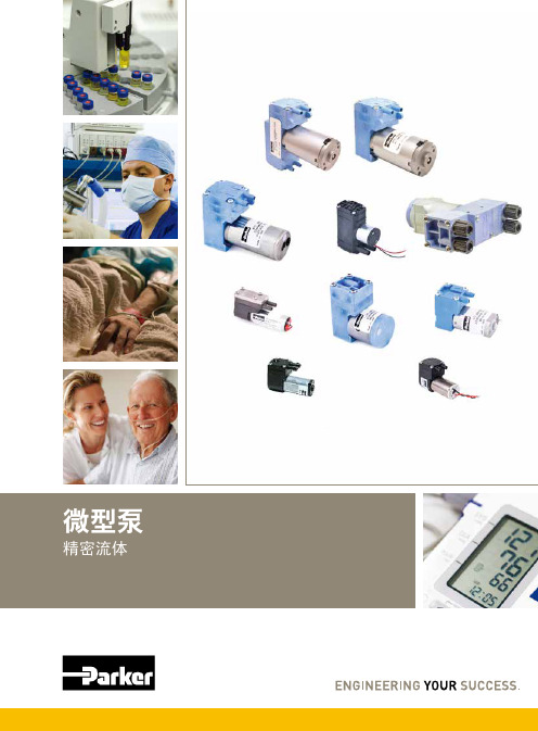
您与运动和控制技术领域的先行者合作,就是希望促进您的业务发展和全球的发展。
从微型电磁阀到高集成型自动化系统,我们的产品对于用于药物研发和病原体检测的救生医疗设备和科学仪器至关重要。
并且对于缩短上市时间和降低总体拥有成本也十分关键。
因此,请与派克合作,准备改变这一切吧!/precisionfluidics 1 603 595-1500目录页T2-05Helix124高效和紧凑型 13.5mm 宽泵 – 高达 800 mLPM高压泵 – 超过5.5 LPM 和高达100 PSI 的压力T2-0320高性能与尺寸比率泵 – 高达2.5 LPMLTC 系列76液体系列传送泵 – 高达 650 mLPMEZ 底座92振动隔离安装系统小型活塞泵(空气)微型泵(空气/气体)微型泵(液体)T2-0494超紧凑型、高效泵 – 高达 7.5LPMBTC-IIS 系列62应用广泛的多功能双头泵系列产品 – 高达 11 LPMBTC 系列52应用广泛的多功能泵系列产品 – 高达6 LPMLTC-IIS 系列84液体系列双头传送泵 – 高达1.5 LPMCTS 系列BTX-Connect 2836高性能紧凑型 20 mm 宽泵 – 高达 2.5 LPM多功能双头和单头泵系列,适合多种应用-高达10 LPMTTC 系列74紧凑、高效、低压泵 – 高达 6 LPMTTC-IIS 系列84紧凑、高效、低压双头泵 - 高达 11 LPM附件4Helix 微型高压泵高达100 PSI (6.9 bar)压力Parker Helix 是一款紧凑型高压泵,旨在实现小型即时临床护理仪器。
Helix 可在挑战性的高海拔环境和无法使用外部压缩空气的应用中实现高压操作。
Helix 泵可提供5.5 LPM 以上的流量和高达100 PSI (6.9 bar)的压力,为性能至关重要且空间有限的台式诊断设备提供了出色的解决方案。
• 集成了用于卸荷的X 阀,可实现高压重启• 内部飞轮可在高压下低速运行• 无油活塞• 简单的安装特性• 带有推入式接头的快速流体连接• 符合RoHS 指令和REACH 标准产品特性• 液上空气• 气动驱动•微流控芯片• 即时临床护理检验• 分子诊断• 核酸纯化•基因组学典型应用典型市场产品规格物理特性电子5微型隔Helix 微型高压泵典型流量曲线• 曲线展示了0.080"偏移泵的流量性能• 使用5.0 Vdc 控制输入时,泵将以大约4400 RPM 的转速和高达8.5 LPM的流量的状态运行,但不建议连续工作。
Sporlan 产品制冷应用手册(2014.11.03)

Sporlan产品
——制冷应用速选手册
前言
斯坡兰(Sporlan)拥有超过75年制冷系统部件供应、服务和系统解决方案的丰富经 验,并持续不断的改进、创新,以提供先进设计、完美制造、高品质产品服务于全球 制冷空调市场。
本手册重点介绍通用制冷系统的部件,如膨胀阀、电磁阀、干燥过滤器、压力控 制开关和压力调节阀等的选型和应用,其它系统部件或应用产品请联系Parker中国各 办事处。
• 最高感温包温度: 100ºC • 最高阀体温度: 121ºC • 最高环境温度: 60ºC • 短暂峰值温度: 149ºC • 最大工作压力: 34 bar • 最大测试压力: 38 bar
R22,R404A,R134a 等HFC,CFC 和HCFC制冷剂。
举例C8EF-VW:
C8
E
F
膨胀阀 类型:C8
R134a
0.44-9.5KW 内平衡或外平衡(0.14-2.71冷吨)
ERV ERVE OVE VVE WVE
Sporlan R22膨胀阀
1/3 1/2 1 2 (冷吨)
1.16-7KW
内平衡 1/3-2冷吨
1/3 1/2 1 2 3 4 5 6 8 10 12 (冷吨)
0.58-31.5KW
外平衡 1/6-9冷吨
9 12 21 30 35 38 45 (冷吨)
31.5-15.8KW
外平衡 9-45冷吨
50 70 (冷吨)
外平衡 50-70冷吨
133-245KW
ERJ
Sporlan R134a膨胀阀
C8膨胀阀 ER、EBS、O、V、W膨胀阀
派克PARKER 马达
专售进口派克马达F11需要请拨打:《150-5979(8003)》(吴工)0595/<2876—7801> (扣扣):77-188-32-47公司的技术核心人员是许多国际和德国标准的委员会的委员,直接参与工业、建筑、医疗、交通等领域有关电气安全和测量标准的制定,这使公司具备了潜在的发展优势,并奠定了公司在低压系统漏电保护技术上的全球领先地位。
产品详细信息,欢迎来电查询!要是您想要的,我都能帮您找到,价格从优!Parker液压产品授权北京分销商。
Parker Hannifin派克汉尼汾是全球一流的运动控制公司, 致力于提供用户一流的服务. 派克是唯一能够给用户提供全方位液压,气动,和机电一体化运动控制方案的制造商之一。
派克公司气动部门,兼并了众多世界著名的气动工厂,使派克气动产品日益壮大,在气动行业中名列前茅,派克旗下的著名品牌:Atlas Automation、SchraderBellows、Telepneumatic、wilkerson、Miller、sempress、Watis、maxam、climax、invensys、ParkerKuroda、Parker TAIYO。
英格索兰气动马达150BMPE88R54-12C德国KRACHT克拉克泵KF40RF1-232-D15SPM大泵连杆瓦2P112860DERRCIK德瑞克振动筛手压油泵G0001992 COREMO科锐盟制动器E4-A1934 DERRICK交流电动机EX30-15-415-007-J DERRICK德瑞克电机EX-2.5HP415/50HZ/3PH 福伊特齿轮泵IPV6-80-101PLT迷你抛绳器M-75MOOG穆格伺服阀743F003ARiovibro测振仪Vm-63a艾默生充电模块HD22010-2诺冠减压阀20AG-X6G/PH100FMC泵M1832HD英格索兰启动马达KK6M现货MOOG伺服阀D631-102C现货GEMU双作用角座阀514-50D-137531GEMU単作用角座阀514-15D-137514 National油封456967v意大利INTERPUMP高压柱塞泵W2141现货ARCOTRONICS电容C20ALGR5680AA0K PRATISSOLI泵KLS36现货INTERPUMP高压柱塞泵W2141威格士减压阀XG2V-6BW-10罗斯蒙特差压变送器3051CD2A22A1AB4M5罗斯蒙特压力变送器3051GP3A2B21AB4M5 Calpeda科沛达水泵TP100EUFM流量开关MN-DSF320LM-16FTCSI50RF现货CAT猫牌柱塞泵5CP3120CSSCAT猫牌柱塞泵5CP3120CSSG1丹佛斯油泵VBHM-D-4-10现货FLOJET泵04300-242现货NUFLO流量计9A-100009536ASCO电磁阀EF8320G202/24DC霍纳编码器HIS1017252现货TROMBETTA启动器NO684-1261-212马勒过滤器PI3405-012现货NOP油泵TOP-206HB马祖奇齿轮泵ALP4A-D-130-S1英格索兰气动马达ST400ICAR72贺德克压力传感器EDS1791P-600-009Parker PUMP and Motor DivisionPart No.3785609TYPE SER NO.F12-090-MF-IV-K-000-000-0Parker PUMP and Motor DivisionPart No.3785518TYPE SER NO.F12-090-MF-IV-D-000-000-0Parker PUMP and Motor DivisionPart No.3780784TYPE SER NO.F12-080-MS-SV-T-000-000-0Parker PUMP and Motor DivisionPart No.3780767TYPE SER NO.F12-080-MF-IV-K-000-000-0Parker PUMP and Motor DivisionPart No.3799989TYPE SER NO.F12-060-MF-IV-K-000-000-0Parker PUMP and Motor DivisionPart No.3799988TYPE SER NO.F12-060-MF-IV-D-000-000-0Parker PUMP and Motor DivisionPart No.3799999TYPE SER NO.F11 060 MS SV T 000Parker PUMP and Motor DivisionPart No.3703665TYPE SER NO.F11 005 MB CN K 000F12-060-MS-SV-T-000液压加气马达CNG加气站泉州双环专业供应派克Parker马达,型号齐全。
Parker Hannifin 71477型号 4-路直动双阀门电磁阀说明书

FLUID CONTROL DIVISIONParker Hannifin Corporation 95 Edgewood Avenue New Britain, CT 06051Telephone (860) 827-2300 IOM7718(Rev0103)INSTALLATION, OPERATING & MAINTENANCE INSTRUCTIONS4-WAY DIRECT ACTING SOLENOID VALVEDUAL SOLENOID 1/4” AND 3/8” NPT VALVE TYPES: 71477DESCRIPTIONThe 71477 valves are 4-way, direct acting, dual solenoid valves. The valve is a 2-position, 4 ported, 4-way directional control valve. The valve requires no minimum operating pressure and no minimum flow for operation. Valves are offered in a brass construction. A metering option is available. Valves may be ordered with either NEMA 2, 4, 4X integrated coils for ordinary locations or NEMA 4, 4X, 7, and 9 for hazardous locations: Divisions I and II; Class I, Groups A, B, C, and D; Class II, Groups E, F, and G. Additional solenoid coils and enclosures are offered as described in our catalog.PRINCIPLES OF OPERATIONThe valve is piped to a double acting cylinder. Valve port A is piped to one port of the cylinder while valve port B is piped to the other port of the cylinder. The solenoid valve functions in such a way that pressure is applied to either side of the piston in the cylinder and exhausted out the opposite side of the pressurized cylinder.Dual Solenoid Valves:Solenoid B last Energized: Flow is from pressure port P to cylinder port B and from cylinder A to exhaust.Solenoid A last Energized: Flow is from pressure port P to cylinder port A and from cylinder B to exhaust.NOTE: No minimum operating pressure is required. Energizing the coil creates a magnetic force sufficient to lift the plunger thereby moving the sleeve assembly within the valve shifting flow from port A to port B.NOTE: The solenoids may be energized momentarily or continuously, depending on the application. Dual solenoids valves are used where the valve must not change position when power fails.CAUTION!! Do not energize both solenoids at the same time.For 3-way applications, one cylinder port can be plugged. Plug port A for normally closed operations or plug port B for normally open operation.FLUID CODESListed below are the codes utilized by Underwriters Laboratories (UL) and the Canadian Standards Association (CSA) for various common fluids. The codes for those fluids that are approved or certified by the agencies for use with each valve are printed on the outside of the individual packaging.CODEFLUID A - Air or nontoxic, nonflammable gases HO - Petroleum based hydraulic oils havingviscosities of up from 125 to 400 SSU at 38o C02 - Nos. 1 and 2 fuel oils, oils having viscositiesnot more than 40 SSU at 38o CW - Water or other aqueous nonflammable liquidsFor the maximum fluid temperatures, as well as valve ambient limitations, check the valve part number on the nameplate and refer to the catalog.CYLINDER METERING DEVICE (Optional Feature)Valves with metering are provided with a built-in flow control device for each cylinder connection. Cylinder flow is controlled by adjusting the metering device for each cylinder connection. To adjust the metering device, release the locknut by turning it counterclockwise. To increase flow, turn the metering stem clockwise. To reduce flow, turn the metering stem counterclockwise. After adjusting to the desired flow, tighten the locknut. The metering stem closest to solenoid B controls cylinder A; the other metering stem controls cylinder B.INSTALLATION INSTRUCTIONSSAFETY INSTRUCTIONS BEFORE INSTALLATION• Carefully read installation, operation and maintenance procedures prior to installing or servicing valve.• Do not use solenoid as a safety shut-off valve when making repairs.• Do not install a valve before depressurizing system down to atmospheric pressure and vent fluid to a safe area before servicing valve.• Verify coil part number and nameplate data including line pressure, voltage and frequency before installing on the valve.• Electrical supply must conform to nameplate rating.Connect coil leads or terminals to the electrical circuit using standard electrical practices in compliance with local authorities and the National Electrical Code.• Before connecting or removing coil from valve, turn off electrical power connecting the coil to the power source.The coil must not be powered unless it is installed on the valve. Otherwise, the coil will overheat and burn out.Mounting position and pressure limits: Valves can be mounted directly on piping and are designed to operate in any position. However, for optimum life and performance the valves should be mounted vertically upright so as to minimize wear and reduce the possibility of foreign matter accumulating inside the operator sleeve area.The diagram shows the mounting hole dimensions in both english and metric units.Piping: Remove protective closures from the ports. Connect line pressure to Port P. Connect cylinder piping according to marking on the valve body. Use of Teflon tape, thread compound or sealants are permissible, but should be applied sparingly to male pipe threads only.CAUTION:Do not allow foreign particles, Teflon tape, or thread compound to enter valve. Only the wrench flats provided on the body ports should be used in applying the torque. Tightening torque should not exceed the following values for each port size:1/4” NPT and 3/8" NPT - 175 in-lbs. Do not use sleeve or enclosure as a lever when applying torque. Connect cylinder lines to port A and B.Media filtration: For protection of the valve, install a suitable strainer or filter in the inlet side as close to the valve as possible. Dirt or foreign material in the media may cause excessive leakage, wear, or in exceptional cases, malfunction. Clean periodically depending on service conditions. Lubrication: Lubrication is not required although air line lubrication will substantially increase valve life.WARNING:Valves to be installed in Hazardous Locations, must be outfitted with Hazardous Location coils only. Verify nameplate data and coil part number before installing the valve.WARNING: Turn off electrical power before connecting the valve to the power source.If the coil assembly is located in an inconvenient orientation, it may be reoriented to facilitate installation. Loosen coil assembly nut, rotate coil assembly to desired position, and then retighten the nut with an input torque of 30-40 in-lbs. [3,4 to 4,5 Nm].Conduit Coil with 1/2” NPT connection: Conduit coils are available with either NEMA 2, 4, 4X integrated coils for ordinary locations or NEMA 4, 4X, 7, and 9 for hazardous locations: Divisions I and II; Class I, Groups A, B, C, and D; Class II, Groups E, F, and G.Use suitable electrical cabling and conduit materials and components meeting applicable NEMA recommendations. DIN Coil and Terminal Box Assembly (Coil / Option Codes D1DB, D2DB, D3DB): Loosen cover screws and swing cover 90o toward the conduit hub in order to access the interior space. Separate the plastic block containing the screw terminals from the metal enclosure using a small Flathead screwdriver. Feed the lead wires through the conduit hub and attach them to the appropriate screw terminal. For electrical connection within the terminal box, use field wire that is rated for 90o C or greater. Snap the plastic block back into place inside the metal enclosure. Replace the cover and hand-tighten the cover screws. Place the gasket over the DIN spades on the coil and press the terminal box and coil together. Secure the terminal box to the coil using the mounting screw provided. Apply 20 to 30 in-lbs. [2,3 to 3,4 Nm] torque to the mounting screw. Screw Terminal Coil and Terminal Box Assembly (Coil / Option Codes S1TB, S2TB, S3TB): Loosen cover screws and swing cover 90o toward the conduit hub in order to access the interior space. Feed the lead wires through the conduit hub and attach them to the appropriate screw terminal. For electrical connection within the terminal box, use field wire that is rated for 90o C or greater. Replace the cover and hand-tighten the cover screws. Press the terminal box and coil together. Secure the terminal box to the coil using the mounting screw provided. Apply 20 to 30 in-lbs. [2,3 to 3,4 Nm] torque to the mounting screw. CAUTION: When the DIN or Screw Terminal coils are used with the Terminal Box Assembly, be sure to apply a wrench to the wrench flats on the conduit hub when installing electrical conduit.Coil/enclosure temperature: Standard valves are supplied with coils designed for continuous duty service. Normal free space must be provided for proper ventilation. When the coil is energized continuously for long periods of time, the coil assembly will become hot. The coil is designed to operate permanently under these conditions. Smoking and/or odor of burning coil insulation will indicate any excessive heating.The chart below shows the maximum valve ambient conditions, as well as the fluid temperatures.Watt RatingCoilClassMax.AmbientTemp.Max.FluidTemp.24 H 140°F 160°FMAINTENANCENote: Depending on service conditions, fluid being used, filtration, and lubrication, it may be required to periodically clean and/or replace worn components. See Disassembly Instructions.CAUTION:Do not expose plastic or elastomeric materials to any type of commercial cleaning fluid. Parts should be cleaned with a mild soap and water solution.DISASSEMBLY INSTRUCTIONSWARNING:Depressurize system and turn off electrical power to the valve before attempting repair.The valve body need not be removed from the line. Note: For inspecting, cleaning or rebuilding, remove piping from Cylinder Ports A and B.To remove the coil assembly:For both ordinary and hazardous location constructions, unscrew the nut on the top of the coil assembly. The wave washer and coil assembly can now be removed.To disassemble the pressure vessel:Valve Disassembly (Refer to Figure 2)1. Remove piping from cylinders A and B anddisassemble valve referring to exploded views providedfor identification and placement of parts.2. Remove coils (4) from the sleeve assembly (5).3. Unscrew sleeves (2) from valve body.4. Remove cover hex bolts (4), cover and cover o-ringfrom valve body.5. Pull the guide / seal assembly and detent spring fromthe armatures and valve body. Then remove the armatures, springs and o-rings.6. If cleaning is all that is required, do not remove bodyexhaust seal plate & o-ring, cylinder seal plate & o-rings. Remove these only if replacement seal platesand o-rings are available.7. To remove the exhaust seal plate and o-ring, insert anappropriate tool or a heavy gauge wire with a bent hookon the end through the center hole in the seal plate.Pull to dislodge seal plate. If the plate will not dislodgeeasily, remove piping from exhaust port and push seatout with a thin rod through the exhaust port.To remove the cylinder seal and o-rings, push sealplate from cover using a thin blunt rod inserted throughhole between Cylinder Port A and Cylinder Port B.When the cover contains metering devices, applycompressed air through either pipe connection or thesmall vent hole in the cover to force out the cover sealplate with the o-rings. If this fails, use the appropriatetool or bent wire described above to dislodge the coverplate with the o-rings.7. All parts are now accessible for cleaning orreplacement. If parts are worn or damaged, install acomplete Parker rebuild kit.CAUTION: Do not use a pipe wrench directly on the sleeve tube.REASSEMBLY INSTRUCTIONSWARNING:Valves equipped with Hazardous Location coils must use Hazardous Location replacement coils only. Verify nameplate data and coil part number before installing the replacement coil.To reassemble the pressure vessel:1. Lubricate all o-rings with ChristoLube Teflon® Pastelubricant or equivalent high-grade silicone grease.Lubricate seating surface of cover cylinder seal plate,body exhaust seal plate and the seal assemblies(including U-cups) with ChristoLube Teflon® Pastelubricant supplied in Rebuild Kit. Note:2. Replace the o-ring on exhaust seal plate and install witho-rings side first into valve body.3. Preassemble spring onto seal assembly and install intoguide assembly. Install remaining seal assembly fromthe opposite end. The seal assemblies will snap ontothe disc spring if pushed evenly and twisted slightly.4. Install guide/seal/spring assembly into the valve bodyand onto the armatures simultaneously.5. Install o-ring onto cover assembly consisting of cover,and cylinder seal plate. Install hex bolts (4) and torquein a crisscross manner to 75 ± 10 in-lbs. [8,5 ± 1,1Nm].6. Move both armatures and down to see that it is properlyengaged and there is no misalignment or binding ofparts.7. Install sleeve o-rings in valve body.8. Replace sleeves into valve body and torque each sleeveto 140 ± 10 in-lbs. [15,8 ± 1,1 Nm].9. Install solenoids. Restore electrical power and linepressure.10. After reassembly, operate the valve a few times to besure of proper operation. A metallic click indicates thesolenoid is operating.CAUTION:To prevent the possibility of personal injury or property damage, check valve for proper operation before returning to service. Also perform internal seat and external leakage tests with a nonhazardous, noncombustible fluid.Refer to the Installation Instructions for remaining installation procedures.CYLINDER METERING DEVICE (OPTIONAL)Description Qty1 MeteringCover 12 MeteringStem 23 StemO-Ring 2 X4 MeteringSeat 2 X5 Spring 2 X6 CoverO-Ring 2 X7 MeteringCap 28 Locknut 29 Wrench 1 xx PARTS CONTAINED IN METERING OPTION REPAIR KITFigure 2 Metering Device (Optional)Metering Device Disassembly (Reference Figure 2)1. Loosen and remove locknut.2. Unscrew metering cap with o-ring and removestern/seat/spring assembly intact.3. Unscrew metering stem from cap and remove spring,metering seat and metering stem o-ring.4. If cleaning is all that is required, do not remove covercylinder seal plate with o-rings. Remove these only if replacement seal plate and o-rings are available. If replacement is necessary, use an appropriate tool or Disassembly to dislodge the seal plate.5. All parts are now accessible for cleaning or replacement. Ifparts are worn or damaged, install a complete Rebuild Kit. Metering Device Reassembly (Reference Figure 2) 1. Reassemble in reverse order of disassembly. Explodedviews provided for identification and placement of parts.2. Lubricate metering cap and stem gaskets withChristoLube Teflon® Paste lubricant or equivalent high-grade silicone grease.3. Replace metering stem o-ring, metering seat and seatspring onto metering stem.CAUTION: Metering seat must be assembled with the large counterbore facing the spring as indicated in Figure 2.4. Install metering cap on stem/seat/spring assembly.5. Install assembly intact. Torque metering cap to 75 ± 10 in-lbs. [8,5 ± 1,1 Nm].6. Replace locknut (loosely) and make adjustments asfollows: To Increase Flow: Turn metering stem clockwise.To Reduce Flow: Turn metering stem counterclockwise.7. After adjusting to desired flow, hold metering stem andtighten locknutREBUILD KITSReference exploded view drawings. Parts marked with an (x) are included in rebuild kits offered for field service. The table lists the rebuild kit number for each valve. When ordering rebuild kits, order by either: 1) rebuild kit number or 2) specify the valve number for which the rebuild kit is needed.Part Number1/4” & 3/8”Porting RebuildKitDescriptive Features71417BN2SN0071417BN3SN007K721 Single Solenoid, Nitrile Seals 71477BN2SN0071477BN3SN007K719 Dual Solenoid, Nitrile Seals 71417BN2SV0071417BN3SV007K720 Single Solenoid, Viton Seals 71477BN2SV0071477BN3SV007K722 Dual Solenoid, Viton SealsRebuild kits are also available for the optional manual stemand metering capability.RebuildKitDescriptive Features7K715 Manual Operator, Nitrile Seals7K716 Manual Operator, Viton Seals7K717 Metering, Nitrile Seals7K718 Metering, Viton SealsTROUBLE SHOOTINGPROBLEM PROCEDUREValve fails to operate – Faulty Control Circuit 1. Check electrical supply with voltmeter. Voltage must agree withnameplate rating.2. If supply voltage is too low, locate and correct cause of low voltage.Should exceed 85% rated voltage.3. Check coil with ohmmeter for shorted or open coil.4. Check the electrical system by energizing the coil. A metallic clicksignifies the solenoid is operating. Absence of a click indicates lossof power. Check for loose or blown out fuses, open-circuit orgrounded coil, broken wire leads or broken splices.5. Make sure that pressure complied with nameplate rating.Valve is sluggish or inoperative - electrical supply and pressure check out. 1. Disassemble valve as per the Disassembly Instructions. Clean outextraneous matter. The armature must be free to move without binding.2. Check all springs, if broken, replace.3. Check that the armature is attached to the guide assembly.Internal Leakage 1. Disassemble valve as per the Disassembly Instructions. Removeextraneous matter. Clean parts in a mild soap and water solution.2. Examine surface of exhaust and cylinder seal plates for dirt. Removeall foreign particles.3. Examine surface of exhaust and cylinder seal plates for nicks andscratches. Replace damaged parts.4. Examine surfaces of both seal assemblies for dirt, nicks or tears.Replace damaged parts.5. Check guide assembly spring. Replace if broken.External leakage at sleeve flange seal to body joint. 1. Check flange seal and replace if damaged.2. Check that sleeve is torqued into body to 130-150 in-lbs.External leakage at flange joint between body and cover. 1. Check that cover hex bolts are torqued with an input torque of 65-85 in-lbs. If leakage persists replacement of cover o-ring may be required.2. Check body and cover sealing surfaces. If damaged, replace valve asnecessary.External leakage at metering speed control device. 1. Check metering cover and stem o-rings for damage. Replace ifnecessary.2. Check that metering cap is torqued into cover to 65-85 in-lbs.External leakage at manual stem. 1. Check O-rings for damage. Replace if necessary.2. Check that manual stem is torqued into body to 130-150 in-lbs.DECLARATIONParker’s Fluid Control Division certifies its valve appliance products complies with the essential requirements of the applicableEuropean Community Directives. We hereby confirm that the appliance has been manufactured in compliance with the applicablestandards and is intended for installation in a machine or application where commissioning is prohibited until evidence has beenprovided that the machine or application is also in compliance with EC directives.The data supplied in the Skinner™ valve catalogs and general Installation, Operating & Maintenance Instructions are to be consulted and pertinent accident prevention regulations followed during product installation and use. Any unauthorized work performed on the productby the purchaser or by third parties can impair its function and relieves Parker Hannifin of all warranty claims and liability for any misuseand resulting damage.A separate Declaration of Conformity or Manufacturer’s declaration is available upon request. Please provide valve identificationnumbers and order serial numbers of products concerned.。
Parker派克汉尼汾公司简介
Parker 为遍布世界五大洲的顾客提供满意的服务,涵盖范围广泛的工业项目,包括研发、 基础系统、生物加工、制药、发电、石油及天然气生产、石化加工和半导体制造等。
» 不间断气体供应系统
VERIFLO 产品
包括实验室、生产在线分析与医院
产品包括汇流排、减压阀、背压阀ห้องสมุดไป่ตู้隔膜 中央供气系统
阀、限流阀、压力安全阀、精微计量阀、
流量控制器等
技术咨询、购买、售后服务
辅助配件
管线装配工具、样品钢瓶、低压铜接头、 低压铜球阀、管夹
»
.
»
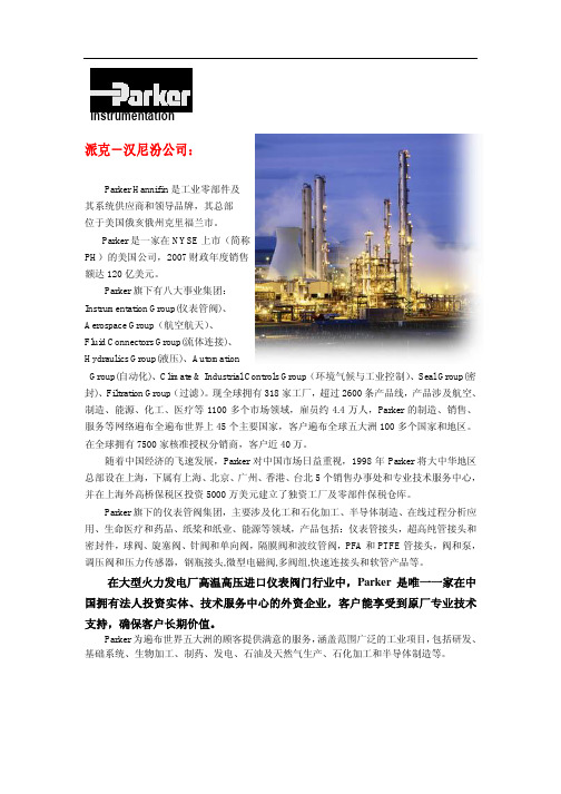
随着中国经济的飞速发展,Parker 对中国市场日益重视,1998 年 Parker 将大中华地区 总部设在上海,下属有上海、北京、广州、香港、台北 5 个销售办事处和专业技术服务中心, 并在上海外高桥保税区投资 5000 万美元建立了独资工厂及零部件保税仓库。
Parker 旗下的仪表管阀集团,主要涉及化工和石化加工、半导体制造、在线过程分析应 用、生命医疗和药品、纸桨和纸业、能源等领域,产品包括:仪表管接头,超高纯管接头和 密封件,球阀、旋塞阀、针阀和单向阀,隔膜阀和波纹管阀,PFA 和 PTFE 管接头,阀和泵, 调压阀和压力传感器,钢瓶接头,微型电磁阀,多阀组,快速连接头和软管产品等。
Instrumentation
派克-汉尼汾公司:
Parker Hannifin 是工业零部件及 其系统供应商和领导品牌,其总部 位于美国俄亥俄州克里福兰市。
Parker 是一家在 NYSE 上市(简称 PH)的美国公司,2007 财政年度销售 额达 120 亿美元。
派克液压中文样本

液压注意 – 用户方责任 错误或不当地选择或使用本样本或有关资料阐述的产品,可能会导致人生伤亡及财产损失! 本样本以及其它由派克汉尼汾公司及其子公司、销售公司与授权分销商所提供的资料,仅供用户专业技术人员在对产品和系统的选型进行深入调查考证时参考。
用户应全面分析自身设备的运行工况、适用的工业标准,并仔细查阅现行的样本,以详细地了解产品及系统的相关信息,通过自己的分析和试验,对产品及系统的独立的最终选择负责,确保能满足自身设备的所有性能、耐用性、维修型、安全性以及预警功能等要求。
对于派克或其子公司或授权分销商而言,应负责按用户提供的技术资料和规范,选择和提供适当的元件或系统,而用户则应负责确定这些技术资料和规范对其设备的所有运行工况和能合理预见的使用工况是否充分和准确。
目录目录页次概述 1 订货代号 2 技术参数 4 变量控制器 5 控制选项 “C”, 压力限定(恒压)变量控制器 5 控制选项 “L”, 负载传感及压力限定变量控制器 6 控制选项 “AM”, 带遥控口的标准型先导式压力限定变量控制器 7 控制选项 “AN”, 带ISO 4401 NG06先导阀安装界面的先导式压力限定变量控制器 8 控制选项 “AE”及“AF”, 带电磁比例调节的先导式压力限定变量控制器 9 控制选项 “AMT”, “ALT”及“LOT”, 带最高压力限定的扭矩限定(恒功率)变量控制器 10 P1性能特性 11典型流量特性 11 典型总效率特性 13 典型轴输入功率特性 15 典型噪声特性 18 典型轴承寿命 20 PD性能特性 22典型流量特性 22 典型总效率特性 24 典型轴输入功率特性 26 典型噪声特性 29 典型轴承寿命 31 安装尺寸 33 P1/PD 018 33 P1/PD 028 36 P1/PD 045 40 P1/PD 060 44 P1/PD 075 49 P1/PD 100 54 P1/PD 140 59 变量控制器安装尺寸 65 可提供的扩展的液压产品 75派克汉尼汾备记派克汉尼汾概述简介, 优点派克汉尼汾简介 • 开式回路用轴向柱塞式变量液压泵 • 中压,连续工作压力280 bar • 高驱动转速型,适用于行走机械; 低噪声型,适用于工业应用 • 静音及高效的控制效能 优点 • 总结构尺寸紧凑 • 低噪声• 流量脉动小,进一步降低噪声• 采用弹性密封,不使用密封垫,从而避免外泄漏的产生• 总效率高,功耗小,减小发热• 采用带无泄漏调节装的简单变量控制器 • 符合SAE 及ISO 标准的安装法兰及油口 • 采用圆锥滚柱轴承,使用寿命长 • 全功率后驱动能力• 后部或侧面油口配置可选• 泄油口的配置对水平安装及驱动轴向上垂直安装均适用• 带有最大及最小排量调节选项 • 具有壳体至吸口单向阀选项,可延长轴封寿命 • 使用、维修方便 脉动容腔技术下列图表所示为侧向油口配置P1/PD 18, 28及45泵采用 “脉动容腔” 技术的效果,脉动容腔可降低泵出口处的压力脉动幅值40-60%,这样,无需增加成本来加装噪声缓冲元件,便可大大降低液压系统的整体噪声,P1系列 PD 系列出口压力p / bar平均压力脉动 / b a rP1 045出口压力脉动2600 rpm 无脉动容腔2600 rpm 带脉动容腔订货代号18 ml, 28 ml, 45ml派克汉尼汾P 类型 01 驱动轴 转向R 5密封材料E 油口配置0 壳体-吸口 单向阀 0 排量调节 018 排量 S 安装法兰 及油口 S 轴封 M 应用范围A 设计系列0 通轴驱动选项 C0控制选项0附加控制选项 00油漆 00修改代号系列 P D * 仅适用于045排量, “S”型安装法兰及油口00 标准型, 无修改M2 按要求修改 代号修改代号 * 适用于028及045排量 ** 仅适用于045排量 代号设计系列 A 现行设计系列5 氟碳橡胶 (FPM) 代号密封材料 A 82-2 SAE A M33x2 M27x2 BSPP 1/4”, 3/8” 101-2 SAE B M42x2 M27x2 BSPP 1/4”, 1/2” 101-2SAE B M48x2M33x2Ø38/25DN51/25BSPP 1/4”, 1/2”B ISO M33x2 M27x2 BSPP 1/4”,3/8”ISO M42x2 M27x2 BSPP 1/4”, 1/2” ISO M48x2M33x2Ø38/25DN51/25BSPP 1/4”, 1/2”代号 018排量 028排量 045排量 安装法兰及油口 安装 法兰 螺纹 油口 辅助 油口 安装 法兰 螺纹 油口 辅助 油口 安装法兰螺纹油口法兰 油口辅助 油口 S 82-2 SAE A SAE 16/12 SAE 4/6 101-2 SAE B SAE 20/12 SAE 4/8 101-2SAE B SAE 24/16Ø38/2561系列SAE 4/10M ISO M33x2 M27x2 M12x1.5 M16x1.5 ISO M42x2 M27x2 M12x1.5 M22x1.5 ISO M48x2M33x2Ø38/25DN51/25M12x1.5M22x1.5代号 018驱动轴 028驱动轴 045驱动轴 01 SAE A 11T 花键SAE B-B 15T 花键 SAE B-B 15T 花键02 SAE 19-1平键Ø0.75” SAE B-B 平键Ø1” SAE B-B 平键Ø1” 08— SAE B 13T 花键 SAE B 13T 花键 04 ISO/DIN 平键, Ø20ISO/DIN 平键, Ø25ISO/DIN 平键, Ø25 06 SAE A 9T 花键— — PD 工业液压用 代号 系列P1 行走机械用 代号 排量 018 18 ml/rev (1.10 in 3/rev) 028 28 ml/rev (1.71 in 3/rev) 045 45 ml/rev (2.75 in 3/rev) 代号 类型 P 开式回路用变量柱塞泵 U*通用 代号应用范围 S 工业液压 (PD) M 行走机械 (P1) R 顺时针 (右转)L 逆时针 (左转)代号 转向 代号 轴封 S 单唇轴封 * 并不具有控制功能,仅在运输时予以防护,详情见第7页的控制说明。
- 1、下载文档前请自行甄别文档内容的完整性,平台不提供额外的编辑、内容补充、找答案等附加服务。
- 2、"仅部分预览"的文档,不可在线预览部分如存在完整性等问题,可反馈申请退款(可完整预览的文档不适用该条件!)。
- 3、如文档侵犯您的权益,请联系客服反馈,我们会尽快为您处理(人工客服工作时间:9:00-18:30)。
15 10
0
10 8
功率(W) AC DC 5.5 6 5.5 6 5.5 6 5.5 6 5.5 6 5.5 6 5.5 6 5.5 6
最大环境 温度˚C
密封件
50
FKM
50
FKM
50
FKM
50
FKM
50
FKM
50
FKM
50
FKM
50
FKM
型号
201DG1EVC2 201DG1GVC2 201DG1JVC2 201DG1LVC2 201DG2EVC2 201DG2GVC2 201DG2JVC2 201DG2LVC2
线圈型号
Din
飞线
C300498 C300524
C300498 C300524
C300498 C300524
C300498 C300524
C300498 C300524
C300498 C300524
C300498 C300524
C300498 C300524
4
微型两通及三通电磁阀
两通直动式 - 常闭 – 不锈钢304阀体
阀体
201DG1EVC2
①
线圈
C300498 3D
②
③
① 阀体型号
② 线圈 C300498: 22毫米DIN线圈, F级
C300524: 22毫米飞线线圈, F级
③ 额定电压代码 参见表1
6
7000系列两通及三通电磁阀 水/油
流量系数 Kv(L/min)
1.0-1.0 2.3-1.0 3.0-1.0
允许的压差(bar)
最小值 AC DC
0
10
10
0
7
7
0
4
4
功率(W) AC DC 5.5 6 5.5 6 5.5 6
最大环境 温度˚C
密封件
50
FKM
50
FKM
50
FKM
型号
301PG2GVC2 301PG2JVC2 301PG2LVC2
1/4” 1/4”
阀体通径 (毫米) 1.2 1.5 2.0 2.5 1.2 1.5 2.0 2.5
流量系数 Kv(L/min)
0.7 1.0 2.3 3.0 0.7 1.0 2.3 3.0
允许的压差(bar)
最小值 AC DC
0
20 20
0
20 15
0
15 10
0
10 8
0
20 20
0
20 15
0
机械特征: 主要材料特征 • 阀体 – 黄铜/不锈钢304 • 密封件 – FKM • 套管组件
- 303不锈钢(套管) - 430FR不锈钢 • 活塞 – 430FR不锈钢 流体 • 空气、水、油 额定电压和功耗 • 请参见表1
常规性能: 响应时间 • 打开/关闭时间: 10 ~ 20毫秒 环境温度 • 最高50 ˚C 接口尺寸BSP(G) • 1/8”, 1/4"
派克克汉汉尼尼汾汾通通用用电磁电阀磁阀
WARNING
FAILURE OR IMPROPER SELECTION OR IMPROPER USE OF THE PRODUCTS AND/OR SYSTEMS DESCRIBED HEREIN OR RELATED ITEMS CAN CAUSE DEATH, PERSONAL INJURY AND PROPERTY DAMAGE. This document and other information from Parker Hannifin Corporation, its subsidiaries and authorized distributors provide product and/or system options for further investigation by users having technical expertise. It is important that you analyze all aspects of your application and review the information concerning the product or system in the current product catalog. Due to the variety of operating conditions and applications for these products or systems, the user, through its own analysis and testing, is solely responsible for making the final selection of the products and systems and assuring that all performance, safety and warning requirements of the application are met. The products described herein, including without limitation, product features, specifications, designs, availability and pricing, are subject to change by Parker Hannifin Corporation and its subsidiaries at any time without notice.
SALE CONDITIONS
The items described in this document are available for sale by Parker Hannifin Corporation, its subsidiaries or its authorized distributors. Any sale contract entered into by Parker will be governed by the provisions stated in Parker’s standard terms and conditions of sale (copy available upon request).
A2
24/50
5.5
OA 110/50,115/50 5.5 C300498
3D 220/50,230/60 5.5
代码
C1 C2
电压
DC12 DC24
功率 线圈
6 6
C300524
A2
24/50
5.5
OA 110/50,115/50 5.5 C300524
3D 220/50,230/60 5.5
如何订购产品(示例)
警告
本样本中产品和/或系统或相关产品出现故障,选型不当或使用不当,均可能导致人身伤亡和财产损失。
本文档以及由派克汉尼汾公司及其子公司和授权经销商提供的其他资料, 为具有技术知识的用户提供进一步研究所需的产品和/或系统选项。重要的是,用户必须对您的应用进行全面的分析, 并对当前产品样本中与产品或系统相关的资料进行评估。由于工作条件以及产品或系统的多样性,用户必须自行分析和测试,并独自承担一切后果,包括:产品和系统的最终选型以及确保满 足应用的所有性能、安全和警告等方面的要求。派克汉尼汾及其子公司可能会随时对本样本中的产品,包括但不限于:产品的特性、产品的规格、产品的结构、产品的有效性以及产品的价格 作出变更而不另行通知。
允许的压差(bar)
最小值 AC DC
0
10 10
0
77
0
44
0
10 10
0
77
0
44
功率(W)
AC DC
5.5
6
5.5
6
5.5
6
5.5
6
5.5
6
5.5
6
最大环境 温度˚C
密封件
50
FKM
50
FKM
50
FKM
50
FKM
50
FKM
50
FKM
型号
301DG1GVC2 301DG1JVC2 301DG1LVC2 301DG2GVC2 301DG2JVC2 301DG2LVC2
适用介质
微型两通及三通电磁阀 7000系列两通及三通电磁阀 NCV系列两通电磁阀 两通蒸汽阀 SCEM系列两通电磁阀
水/油 水/油
水/油
蒸汽 蒸汽
空气 空气 空气
3
微型两通及三通电磁阀
水/油
空气
微型两通及三通电磁阀
• 通用电磁阀 • 两通直动式 • 适用于多种介质 • 可供选择的线圈:F级 • 标准密封件:FKM
销售条件
本样本中的所有产品均由派克汉尼汾公司及其子公司和授权经销商销售。与派克签订的任何销售合同均按照派克标准条件和销售条件中规定的条款执行(提供复印件备索)。
2
通执用行机电构磁阀
页码
页码
微型两通及三通电磁阀 ..........................................................................................................................4 7000系列两通及三通电磁阀 ................................................................................................................... 7 NCV系列两通电磁阀............................................................................................................................. 10 两通蒸汽阀 ........................................................................................................................................... 12 SCEM系列两通电磁阀.......................................................................................................................... 14