完整高效可靠 派克滤清器全系产品介绍
派克机电产品纵览说明书

■ᅠ高技术应用的控制器■ᅠ基于工业以太网的运动控制系统■ᅠ集成多轴运动控制器■ᅠ智能伺服驱动器■ᅠ工业以太网多轴伺服驱动器■ᅠ通用伺服驱动器■ᅠ智能直流调速器■ᅠ通用直流调速器派克机电产品纵览运动控制驱动技术直流调速器■ᅠ智能交流变频器■ᅠ通用交流变频器交流变频器2■ᅠ滚珠丝杠驱动工作台■ᅠ直线电机驱动工作台■ᅠ高精度微型工作台■ᅠ经济型■ᅠ高精度高精度执行器与工作台行星齿轮减速机■ᅠ伺服电机■ᅠ防爆伺服电机■ᅠ高速大功率伺服电机■ᅠ高性能车载电机■ᅠ直线电机组件■ᅠ直驱电机■ᅠ高性能伺服电机■ᅠ电动缸■ᅠ线性执行器电机执行器3ACR 系列是派克主要的独立封装的运动控制器,能够实现多达八轴的运动控制。
简单易用的项目开发组件,使应用系统构建及维护快速,高效。
ACR74C/78C 是4轴/8轴运动控制器;ACR74T 是集成4轴步进电机驱动器的驱控一体机;ACR74V/78V 是集成4轴/8轴低压伺服驱动器的驱控一体机。
强大、集成化和为机械市场设计的派克自动化运动控制器(PAC)为OEM 提供了基于标准的自动化解决方案,能够满足严苛的应用要求。
PAC 将先进逻辑、多轴运动、信号处理和网络发布的可视化整合到一个以性能为导向的解决方案中,进而消除不必要的硬件和通信链接,并提高开发者的效率。
PAC网络架构派克自动化运动控制器 - PACACR 控制器系列•ᅠ K eywords: PAC CPU 运算能力更强•ᅠP AC: EtherCAT, 多轴插补•ᅠA CR:模拟量模式,简单易用ACR7C/7V ACR7000PAC3404智能伺服驱动器 - Compax3Compax3是派克汉尼汾不同国家和地区推出的伺服驱动器产品。
驱动器系列包括单轴,多轴驱动器,还有液压控制器。
这一系列驱动的功率从1到110kVA。
这一伺服驱动器的整个研发及制造过程全部在德国完成。
另外的生产基地也在美国建成。
作为一款销往不同国家和地区的伺服驱动控制器,Compax3在世界各地都有销售。
派克TTF系列过滤器中文样本
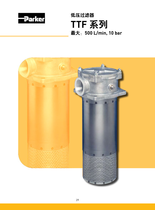
TTF最大:500 L/min, 10 bar特点&好处典型应用• 垃圾车• 移动式起重机• 动力站• 轮式装载机• 钻井设备TTF 系列回油管路过滤器TTF 油箱顶置回油管路过滤器内设有磁铁和低阻滞的全流量旁通阀,具有预过滤功能。
由于采用了由里向外的过滤原理,受污染的油液因此不可能倒流回系统。
TTF 系列过滤器可处理的流量最大可达500l/min ,最大压力可达10bar ,用户可选过滤器端盖上的注油口,第二个回油口和用户自定义的扩散器。
也可提供集成式的(TSR 系列)带有4个回油口的过滤器滤头。
TTFTSR1345678101112131415169a9b类型 1-125/2-170/2-230/2-3002-400/2-500类型1-60/1-90/1-120滤芯安装间隙F8136最低油位安装孔B 137LHØ50Ø102±1Ø410.33.2BAAØ1656481814x ISO228G 1/8”(BSP)4x Ø1112工作压力:最大. 10 bar .安装方式:油箱顶置安装.接口:螺纹 BSP 接口.法兰接口可按要求提供集成式滤头TSR 可按要求提供流量可达 250 l/min.过滤器外壳:铝质滤头和端盖.密封材料:丁腈橡胶, 氟橡胶, 氯丁橡胶.工作温度范围:-40 - +120°C.旁通阀设定:开启压力 0.8 / 1.5 或 2 bar .其它要求请咨询过滤效果:决定于多次通过实验符合ISO 16889.液流疲劳特性:过滤材质可确保获得最佳的疲劳寿命过滤材质:Microglass III & Ecoglass III LEIF ®滤芯.也可提供10μm 纸质纤维和40μm 不锈钢金属网滤芯的爆破压力:10 bar (ISO 2941)压力指示器选项:设定值 0.7 或 1.2 bar .其他的设定值请咨询.目视压力表.电讯式压力继电器.选项:扩散器列类型 P (直管,无开孔板区域)扩散器 T (带有封闭的扩散器端帽和开孔板区域,当进入油箱的油液接近油箱底部或为了确保进入的油液处于油箱液位之下时推荐使用)磁铁组件:标准的 TTF400 和 500 作为标准供货不包括磁铁端盖上注油口(可选)堵塞.过滤器滤芯:LEIF ®滤芯带有可多次使用的金属滤芯护套 可选传统的带有碳钢端帽的滤芯.LEIF ®滤芯专利产品可保证使用真正原装产品。
Parker F602 高流量系列滤器说明书

Drains and Options Blank Manual Twist DrainQ External Heavy Duty Auto Drain R Internal Auto Drain USemi-Auto DrainHi-Flow F602 SeriesBOLD ITEMS ARE MOST POPULAR.Ordering InformationF 602 — 06 W J — /**BowlE 32 oz. Large Capacity Metal without Sight GaugeW 16 oz. Metal withSight GaugeElement G 5 Micron J 40 MicronPort Size 06 3/4 Inch 08 1 InchPort Threads — NPT G BSPPF602-06W, F602-08W Filter DimensionsA 4.90(124)B 7.88(200)C 8.72(221)D 4.06(103)E 0.84(21)F 2.45(62)F602-06E, F602-08E Filter DimensionsA 4.90(124)B 11.10(282)C 11.94(303)D 4.06(103)E 0.84(21)F 2.45(62)inches (mm)Features• Excellent water removal efficiency• For heavy duty applications with minimum pressure drop requirement.• Unique deflector plate that creates swirling of the air stream ensuring maximum water and dirt separation.• Large filter element surfaceguarantees low pressure drop and increased element life.• 40 micron filter element standard, 5 micron available.• Metal bowl with sight gauge standard.• Twist drain as standard, optional auto drain.• Large bowl capacity.• Optional high capacity bowl(s) available.• High Flow: 3/4" – 270 SCFM § 1" – 300 SCFM §3/4 & 1 Inch PortsStandard part numbers shown bold.For other models refer to ordering information below.§ SCFM = Standard cubic feet per minute at 90 psig inlet and 5 psig pressure drop.Port Size NPTTwist DrainInternal Auto DrainMetal Bowl / Sight Gauge - 16 oz.3/4"F602-06WJ F602-06WJR 1"F602-08WJ F602-08WJR Metal Bowl without Sight Gauge - 32 oz.3/4"F602-06EJ F602-06EJR 1"F602-08EJF602-08EJREngineeringLevel * Will be Entered at Factory.AutomaticDrainManual Drain102345Flow - SCFM P r e s s u r e D r o p - P S I GP r e s s u r e D r o p - b a r.1.2.3Primary Pressure - PSIG 2510050751501.73.4 5.2 6.910.3Primary Pressure - bar 040608010012014020Flow - dm /s3nFlow - SCFMP r e s s u r e D r o p - P S I GP r e s s u r e D r o p - b a r.1.2.3040608010012014016020Primary Pressure - PSIG 1.7 3.4 5.26.910.3Primary Pressure - barFlow - dm /s3nTechnical Specifications – F602Technical InformationF602 Filter Kits & AccessoriesBowl Kits –Aluminum (E) 32 oz. ...........................................................BK603B Zinc with Sight Gauge (W) 16 oz. ...................................BK605WB Drain Kits –External Auto (E) 32 oz. .....................................................SA603D External Auto (W) 16 oz. ....................................................SA602D Internal Auto (All) ............................................................SA602MD Manual (All) ..................................................................SA600Y7-1 Semi-Automatic “Overnight” Drain ....................................SA602A7 (Drains automatically under zero pressure)Filter Element Kits –40 Micron (All) ...................................................................EK602B 5 Micron (All) ...................................................................EK602VB Mounting Bracket Kit(Pair or 2 Kits Pipe Mounted Brackets needed) –(3/4" Unit) ...................................................................SA200AW57 (1" Unit) ......................................................................SA200CW57Repair Kits –Deflector, Baffle Assembly, and Retaining Rod (E,W) .......RK602B External Auto Drain (All) ....................................................RK602D Internal Auto Drain (All) ..................................................RK602MD Metal Bowl with Sight Gauge (W) 16 oz. .....................RKB605WBSpecificationsBowl Capacity –Aluminum Bowl (E) 32 oz. ..............................................32 Ounces Zinc Bowl (W) 16 oz. ......................................................16 Ounces Port Threads ...................................................................3/4, 1 InchPressure & Temperature Ratings – Aluminum Bowl (E) 32 oz. – 0 to 300 psig (0 to 20.4 bar) 40°F to 150°F (4.4°C to 65.6°C) Zinc (W) 16 oz. – 0 to 250 psig (0 to 17.2 bar)40°F to 150°F (4.4°C to 65.6°C)With Internal Auto Drain (R) – 20 to 175 psig (1.4 to 11.9 bar)40°F to 125°F (4.4°C to 52°C) With External Auto Drain (Q) – 0 to 250 psig (0 to 17.2 bar)40°F to 150°F (4.4°C to 65.6°C)Weight –Aluminum Bowl (E) 32 oz. ............................... 7 lb. (3.18 kg) / Unit 28 lb. (12.70 kg) / 4-Unit Master Pack Zinc Bowl (W) 16 oz. ..................................... 6.3 lb. (2.86 kg) / Unit 25 lb. (11.34 kg) / 4-Unit Master PackMaterials of ConstructionBody .............................................................................................Zinc Bowls –(E) 32 oz. ........................................Aluminum without Sight Gauge (W) 16 oz. ......................................................Zinc with Sight Gauge Drain –Manual T wist & Overnight .......................................................Brass Housing “R” ............................................................................Acetal Housing “Q” ..........................................................................Bronze Filter Elements –40 Micron (Standard) ................................................Polypropylene 5 Micron (Optional) ...................................................Polypropylene Seals ...........................................................................................Nitrile Sight Gauge ...............................................................................Nylon( ) = Bowl TypeFloat (Inside Bowl) Manual Push ButtonDrain(Outside Bowl)Drain (1/4" NPTF)Connection Through Bowl (1/8" NPSM)“Q” Option External Heavy Duty Auto Drain SA602D / SA603DFor heavy duty applications where the filter is being used to remove large volumes of liquid and/or particulate matter from the airstream, the external automatic drain (“Q” option) should be used.Air Line Filters。
Parker 15 40 80CN系列核心无电机中压滤芯说明说明书

Applications• Compressor Lube Oil• Off-line Filter Loops• Machine Tools(Automotive Standard)• Hydrostatic DriveCharge Pumps• Mobile Equipment• Pilot Lines For Servo Controls • Oil Patch Drilling Equipment • Injection MoldingThis partial list of applications for Parker “CN” series filters has a common factor, the need for an economical, medium pressure range filter with excellent fatigue pressure ratings. Prior to the availability of the “CN” filter, applications such as those listed were restricted by limitationsof a spin-on can, or forced into the higher cost range of high pressure filters.The “CN” series fills thisgap, and now with the newly increased fatigue rating from 550 to 800 psi, the applications are expanded.Ecoglass IIIReplacement Elements Ecoglass III represents the merging of high performance filtration technology with environmentally conscious engineering. The Ecoglass III line of replacement elements feature 100% non-metallic construction. The design reduces solid waste and minimizes disposal costs for industry. The non-metallic construction means lightweight elements (60% less weight) for easier servicing.The Ecoglass III elements utilize the same proprietary media design as our Microglass III line of replacement elements.With Ecoglass III, a reusable core is installed into the filter housing and remains in service throughout the life of the assembly.FeaturesPortsSAE, NPT or flange face (80CN) provides mounting flexibility.Diametral (side) SealDust SealProtects head and bowl threads from external contamination buildup.Element AssemblyHigh efficiency (B x >200), high capacity Ecoglass III media with it’s multi-layered design is unequalled in performance.Element Condition IndicatorsAvailable in visual or electrical, with a choice of several power connections (E3 shown).HeadCast aluminum is rugged with small profile for easy mounting.BypassCartridge style bypass has good sealing characteristics and low hysteresis. Choice of two settings to match application needs.BowlAluminum is lightweight and corrosion resistant.Drain Port (optional)Optional drain port allows15CN-1 Element PerformanceFlow vs. Pressure LossResults typical from Multi-pass tests run per test standard ISO 16889 @ 10 gpm to 100 psid terminal - 10 mg/L BUGLRefer to Appendix on pages 264-265 for relationship to test standard ISO 4572.Ef ciency %Ef ciencyBeta Rating 10001000099.999.599.010020020250.095.0Micron Size (c)PSID Capacity123456204060801000 1 2 3 4 5 6 7Capacity (grams)BARP S I D 25201510501.51.00.50.0BARLPM0 10 20 30 40 50 60 70P S I D25201510501.51.00.50.0BARLPM0 10 20 30 40 50 60 7015CN-2 Element PerformanceResults typical from Multi-pass tests run per test standard ISO 16889 @ 15 gpm to 100 psid terminal - 10 mg/L BUGL Refer to Appendix on pages 264-265 for relationship to test standard ISO 4572.Flow vs. Pressure LossEf ciency %Ef ciencyBeta Rating100099.999.599.010020020250.095.0Micron Size (c)PSIDCapacity12345620406080100Capacity (grams)BAR40CN-1 Element PerformanceResults typical from Multi-pass tests run per test standard ISO 16889 @ 15 gpm to 100 psid terminal - 10 mg/L BUGLRefer to Appendix on pages 264-265 for relationship to test standard ISO 4572.Flow vs. Pressure LossPSID Capacity1234560204060801001020 3040Capacity gramsBARPS I D252015105BARLPM1.51.00.50.00 50 100 150 200 250 300 350P S I D2520151050BARLPM1.51.00.50.00 50 100 150 200 250 300 35040CN-2 Element PerformanceResults typical from Multi-pass tests run per test standard ISO 16889 @ 30 gpm to 100 psid terminal - 10 mg/L BUGLRefer to Appendix on pages 264-265 for relationship to test standard ISO 4572.Flow vs. Pressure Loss40CN-3 Element PerformanceResults typical from Multi-pass tests run per test standard ISO 16889 @ 45 gpm to 100 psid terminal - 10 mg/L BUGLRefer to Appendix on pages 264-265 for relationship to test standard ISO 4572.Flow vs. Pressure LossPSID BARCapacity1234562040608020406080100120Capacity (grams)80CN-1 Element PerformanceP S I D2520151050BARLPM1.51.00.50.00 50 100 150 200 250 300 350LPMP S I D 1086420BAR0 50 100 150 200 250 300 350Results typical from Multi-pass tests run per test standard ISO 16889 @ 45 gpm to 100 psid terminal - 10 mg/L BUGLRefer to Appendix on pages 264-265 for relationship to test standard ISO 4572.Flow vs. Pressure LossPSID Capacity123456020406080100Capacity grams020406080100BAREf ciency %Ef ciencyBeta Rating 10001000099.5100200202Micron Size (c)80CN-2 Element PerformanceFlow vs. Pressure LossResults typical from Multi-pass tests run per test standard ISO 16889 @ 70 gpm to 100 psid terminal - 10 mg/L BUGLRefer to Appendix on pages 264-265 for relationship to test standard ISO 4572.PSID Capacity12345602040608010020406080 100 120 140Capacity gramsBARSpecificationsMaximum Allowable OperatingPressure (MAOP):1000 psi (69 bar)Rated Fatigue Pressure:800 psi (55.2 bar)Design Safety Factor: 2.5:1Operating T emperatures:Nitrile: -40°F (-40°C) to 225°F(107°C)Fluorocarbon: -15°F (-26°C) to225°F (107°C)Element Collapse Rating:Standard: 150 psi (10.3 bar)Materials:Head and Bowl: AluminumIndicators: Alum. body, plastic connec-torsBypass: NylonWeights (approximate):Model Single length Double length15CN 2.5 lb. (1.13 kg) 3.5 lb. (1.6 kg)40CN 4.5 lb. (2.00 kg) 5.5 lb. (2.49 kg)80CN 12.4 lb. (5.62 kg) 15.2 lb. (6.89 kg)Element Condition Indicators:Visual 360° green/red auto resetElectrical/Visual5A @ 240VAC, 3A @ 28VDCElectrical-Heavy Duty.25A(resistive) MAX 5 watts12 to 28 VDC & 110 to 175 VACColor code:White (common)Black (normally open)Blue (normally closed)Drawings are for reference only.Contact factory for current version.A. Stop the system’s power unit.B. Relieve any system pressure in the filter line.C. Drain the filter bowl if drain port option is provided.D. Loosen and remove bowl.E. Remove element by pulling downward with a slight twisting motion and discard.F . Check bowl o-ring for damage and replace if necessary.G. Lubricate element o-ring with system fluid andplace on post in filter head.H. Install bowl and tighten to specified torque. 15CN - 15-20 ft. lbs 40CN - 42-50 ft. lbs80CN - 60-70 ft. lbsI. Confirm there are no leaks after powering thesystem.Element Service InstructionsParts ListSelect the desired symbol (in the correct position) to construct a model code.Please note the bolded options reflect standard options with a reduced lead-time. Consult factory on all other lead-time options.How to OrderReplacement Elements (Ecoglass)Global products as identified are offeredworldwide through all Parker locations and utilize a common ordering code.。
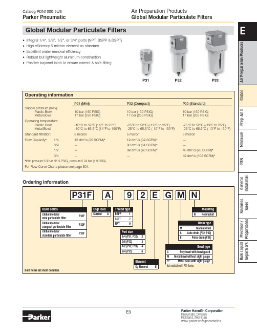
Parker Pneumatic全球模块化粒子过滤器产品说明说明书
E5
P33 Aluminum ABS Polycarbonate Aluminum Nylon Polypropylene Acetal Sintered Polyethylene Nitrile Polycarbonate
Parker Hannifin Corporation Pneumatic Division Richland, Michigan /pneumatics
Filter element
Seals
Sight gauge
Metal bowl
P31 Aluminum N/A Polycarbonate Aluminum Nylon N/A Acetal Sintered Polyethylene Nitrile N/A
P32 Aluminum N/A Polycarbonate Aluminum Nylon Polypropylene Acetal Sintered Polyethylene Nitrile Polycarbonate
18.3 (0.72)
116.3 (4.58)
4mm (5/32") I.D. Tube Barb fitting
P33
73 (2.87)
Bowl 33.3 removal (1.31) clearance
73 (2.87)
36 (1.42)
26 (1.02)
Air Preparation Products Global Modular Particulate Filters
S* Metal bowl with sight gauge
* Not available with P31 Series.
Bulk Liquid Precision / Stainless General
Parker domnick hunter OIL-X 高效压缩空气滤器系列说明书

/gsfUnique filter elementSpecially constructed for reducedair flow velocity, reduced pressureloss, increased dirt holding capacity,and improved efficiency. Includes a12-month air quality guarantee.Flow management systemSpecially engineered ‘bell mouth’,with 90-degree elbow, flow distributorand conical flow diffuser, to promote aconsistent, optimum air flow.Filter housingDesigned to allow easy maintenanceand element replacement, and coveredby a 10-year guarantee.Flexible connectionsA wide range of port sizes and filterconnections, for added flexibility.Epoxy coatingFinished with alocrom corrosionprotection and a tough, dry powderepoxy coating for a high quality feel.Parker domnick hunter OIL-X; a new series ofcompressed air filters, taking efficiency to adifferent level.Built on Parker’s worldwide expertise in filtration, the OIL-X rangehas been developed to ensure consistent outstanding air quality,guaranteed for 12 months - and third-party validated to meetISO 8573-1.Combining the unique filterelement with a speciallydesigned advanced air flowmanagement system, the Parkerdomnick hunter OIL-X range isengineered to not only deliver airquality in accordance withISO 8573-1 classifications, butit does so with a extremely lowdifferential pressure - ensuringmaximum efficiency andproductivity.MARKETLEADING LOWDIFFERENTIALPRESSURECOMPRESSED AIR FILTERSOIL-X RedefinedGrades AOP and AAP for Coalescing Liquids and Particle Removal in Compressed Air or Gaseous Nitrogen Grade ACSP for Oil Vapour RemovalFilter coding examplesBulk liquid removal in Compressed Air or Gaseous Nitrogen Systems Delivering Filtration Efficiency > 92% based on ISO8573.9Product SelectionStated flows are for operation at 100 psi g (7 bar g) with reference to 68°F (20°C), 14.5 psi g (1 bar g), 0% relative water vapor pressure.171819202482632772901. Obtain the minimum operating pressure and maximum compressed air flow rate at the inlet of the filter.2. Select the correction factor for minimum operating pressure from the CFP table (always round down e.g. for 5.3 bar, use 5 bar correction factor)3. Calculate the minimum filtration capacity: Minimum Filtration Capacity = Compressed Air Flow Rate x CFP4. Using the minimum filtration capacity, select a WS model from the flow rate tables above (WS selected must have a flow rate equal to or greater than the minimum filtration capacity)5. WS models are supplied with a float drain as standard. For pressures of 232 to 290 psi g (16 to 20 bar g ), a manual drain must be used.Benefits:• For the removal of bulk condensed water and liquid oil• Used to protect coalescing filters from bulk liquid contamination • High liquid removal efficiencies at all flow conditions• Helps provide air quality in accordance with ISO 8573-1:2001.• Suitable for all compressed air applications.• Suitable for all compressor types, including variable flow. • Low pressure losses for low operational costs.• Low lifetime costs.• Helps reduce the release of CO2 into the environment.• Lloyds & CRN registeredMUST HAVE Manual DrainOrder "MX" OptionOIL-X Bulk Water Separators"Oil-X Redefined, the unique low energy solution with independently validated performance."Particle Removal down to 1 micron Max Remaining Oil Content 0.5mg/m3 delivering Filtration of 99.925%Initial Dry Differential Pressure <70mbar (1.0 psi) Initial Saturated Pressure drop <125mbar (1.8psi)Technical DataAOP010-055 MODELS COME WITH FLOAT DRAIN & DPI AS STANDARDStated flows are for operation at 100 psi g (7 bar g) with reference to 68°F (20°C), 14.5 psi g (1 bar g), 0% relative water vapor pressure.17181920248263277290Accessory Kits (unless stated otherwise all Differential Pressure Monitors, Gauges and Drains have MAX Operating Pressure 232 psig)1. Obtain the minimum operating pressure and maximum compressed air flow rate at the inlet of the filter.2. Select the correction factor for minimum operating pressure from the CFP table (always round down e.g. for 5.3 bar, use 5 bar correction factor)3. Calculate the minimum filtration capacity: Minimum Filtration Capacity = Compressed Air Flow Rate x CFP4. Using the minimum filtration capacity, select a filter model from the flow rate tables above (filter selected must have a flow rate equal to or greater than the minimum filtration capacity)5. AO models are supplied with a float drain as standard. For pressures of 232 to 290 psi g (16 to 20 bar g ), a manual drain must be used.MUST HAVE Manual Drain -Order "MX" OptionOIL-X Redefined GRADE AOPGrade AO Coalescing Liquids and Particle Removal in Compressed Air or Gaseous Nitrogen"Oil-X Redefined, the unique low energy solution with independently validated performance."Particle Removal down to 0.01 micron Max Remaining Oil Content 0.01mg/m3 delivering Filtration of 99.9999%Initial Dry Differential Pressure <70mbar (1.0 psi) Initial Saturated Pressure drop <125mbar (1.8psi)Technical DataAAP010-055 MODELS COME WITH FLOAT DRAIN & DPI AS STANDARDStated flows are for operation at 100 psi g (7 bar g) with reference to 68°F (20°C), 14.5 psi g (1 bar g), 0% relative water vapor pressure.17181920248263277290Accessory Kits (unless stated otherwise all Differential Pressure Monitors, Gauges and Drains have MAX Operating Pressure 232 psig)1. Obtain the minimum operating pressure and maximum compressed air flow rate at the inlet of the filter.2. Select the correction factor for minimum operating pressure from the CFP table (always round down e.g. for 5.3 bar, use 5 bar correction factor)3. Calculate the minimum filtration capacity: Minimum Filtration Capacity = Compressed Air Flow Rate x CFP4. Using the minimum filtration capacity, select a filter model from the flow rate tables above (filter selected must have a flow rate equal to or greater than the minimum filtration capacity)5. AA models are supplied with a float drain as standard. For pressures of 232 to 290 psi g (16 to 20 bar g ), a manual drain must be used.MUST HAVE Manual Drain -Order "MX" OptionOIL-X Redefined GRADE AAPGrade AA Coalescing Liquids and Particle Removal in Compressed Air or Gaseous Nitrogen"Oil-X Redefined, the unique low energy solution with independently validated performance."Oil Vapour removal down to 0.003 mg/m3Initial Dry Differential Pressure <140mbar (2.0 psi)Technical DataStated flows are for operation at 100 psi g (7 bar g) with reference to 68°F (20°C), 14.5 psi g (1 bar g), 0% relative water vapor pressure.17181920248263277290Accessory Kits (unless stated otherwise all Differential Pressure Monitors, Gauges and Drains have MAX Operating Pressure 232 psig)1. Obtain the minimum operating pressure and maximum compressed air flow rate at the inlet of the filter.2. Select the correction factor for minimum operating pressure from the CFP table (always round down e.g. for 5.3 bar, use 5 bar correction factor)3. Calculate the minimum filtration capacity: Minimum Filtration Capacity = Compressed Air Flow Rate x CFP4. Using the minimum filtration capacity, select a filter model from the flow rate tables above (filter selected must have a flow rate equal to or greater than the minimum filtration capacity)MUST HAVE Manual Drain -Order "MX" OptionOIL-X Redefined GRADE ACSPGrades ACSP Oil Vapor Removal Removal FilterGrades AOP, AAP & ACSP Weights and DimensionsWSP010-055 Water Separator AOP/AAP010-035Filter060 G4"FilterOIL-X RedefinedPage 12 Filter DimensionsFor more information please contact your l oc al sales office or visit www.park e r.c om/gsfParker has a continuous policy of product development and although the company r eserv es the right to changes specifications, it attempts to keep customers informed of any alt er ations.© 2017 Parker Hannifin Corporation. All rights reserved.Catalogue: PISOILX-04-ENParker Hannifin CorporationIndustrial Gas Filtration and G eneration Division4087 Walden AvenueLancaster, NY 14086 phone716 686 6400/gsfYour local authorized Parker distributor。
Parker Hannifin 900FH和1000FH燃油过滤器 水分离器商品说明书

Turbine Series900FH and 1000FHFuel Filter/Water SeparatorsTurbine Series filters protect precision engine components from dirt, rust, algae, asphaltines, varnishes, and especially water, which is prevalent in engine fuels. They remove contaminants from fuel using the following legendary three stage process:Stage 1 - SeparationAs fuel enters the assembly, it moves through the centrifuge and spins off large solids and water droplets, which are heavier than fuel, and fall to the bottom of the collection bowl.Stage 2 - CoalescingSmall water droplets bead-up on thesurface of the conical baffle and cartridge filter. When heavy enough, they too fall to the bottom of the collection bowl.Stage 3 - FiltrationProprietary Aquabloc ®II cartridge filters repel water and remove contaminants from fuel down to 2 micron (nominal). Aquabloc ®II cartridge filters arewaterproof and effective longer than water absorbing filters.Instruction Part Number 12960 Rev DContact Information Parker Hannifin Corporation Racor Division P .O. Box 32083400 Finch Road Modesto, CA 95353phone 800 344 3286209 521 7860fax 209 529 3278****************/racor/racorproductsGetting StartedThe following customersupplied materials shouldbe on hand before beginning installation.Shop Towels.• Diesel Fuel (about 1 • gallon).Thread Sealant (no thread • tapes).Parker Super O-Lube • (RK 31605) or equivalent.Fuel Hose.• Mounting Hardware (3/8"• or M10 fasteners).Inlet/Outlet Fittings.•2Mounting Information90°10°10°VNote: Mount the filter assembly as close to vertical (V) as possible.Do not exceed 10° from vertical or the assembly may not function properly.Note: Fastener size 3/8" (M10) for Mounting brackets.1000FH(27.7 cm)Adjustableby ±2.1 in.5.8 in.900FH13.5 in5.8 in.Installation DiagramValve 1Valve 23Installation InstructionsAdjustable, one-piece clamp-type mounting brackets (with grade 5 fasteners) are included for ensured durability. The 900FH uses one mounting bracket and 1000FH uses two mounting brackets, both can be adjusted for a secure fit.Positioning Filter• I nstall Turbine Series filter on vacuum side of fuel transfer pump for optimum water separating efficiency. Note: See installation diagram.• K eep fuel line restrictions to a minimum. Locate filter assembly between horizontal planes of bottom of fuel tank and inlet of fuel pump, if possible. If filter is installed in an application where the fuel tank is higher than the filter, a shut-off valve must be installed between tank and filter assembly INLET. This will be used when servicing replacement filter.Before Installation• O btain good ventilation and lighting.• M aintain a safe working environment.• T he engine must be off for installation.• D O NOT smoke or allow open flames near the installation.Installing Filter• C ompletely remove any vacuum side filters in fuel line between fuel tank and fuel pump. This is where filter assembly will be mounted. Leaving these filters in place will add to the fuel linerestriction. Filter heads cast into engine, or that are non-removable, or hard pipedshould be serviced with a new filter and left in place.• K eep fuel flow restriction values to a minimum. Always use maximum size fuel hose possible. Do not make sharp bends with flexible fuel hose as kinks may occur. Avoid useof two 45° elbow fittings where one 90° elbow will work.• W hen routing hose, avoidsurfaces that move, have sharp edges, or get hot (such as exhaust piping).Priming Instructions1. R emove T-handle and lid from top of filter.2. F ill filter with clean fuel.3. L ubricate lid gasket andT-handle O-ring with clean fuel or motor oil.4. R eplace lid and T-handle and tighten snugly by hand only - do not use tools .5. I f applicable, refer toequipment Operator’s Service Manual to complete fuel priming procedure.6. S tart engine and check for fuel system leaks. Correct as necessary with engine off and pressure relieved from filter assembly.Draining WaterFrequency of water draining is determined by the contamination level of fuel. Inspect or draincollection bowl of water daily or as necessary. Collection bowl must be drained before contaminants reach the top of the turbine or when Water Detection Module (optional) indicates a drain is required.Vacuum Side Applications1. C lose inlet valve (or valve #1) and open self-venting drain on bottom of bowl.2. C lose drain after all water and contaminants have been evacuated - DO NOT leave drain open too long as it will eventually completely drain entire filter of water AND fuel.3. Follow Priming Instructions .Pressure Side Applications1. O pen self-venting drain on bottom of bowl. Head pressure will push any water and contaminants out of drain while keeping filter primed.2. C lose drain after all water and contaminants have been evacuated - DO NOT leave drain open too long as it will eventually completely drain entire filter of water AND fuel, and possibly drain entire tank.Service Instructions4Frequency of filter replacement is determined by contamination level of fuel. Replace filter every 10,000 miles, every 500 hours, every other oil change, when vacuum gauge (optional) reads between 6 to 10 inches of mercury (inHg), if power loss is noticed, or annually, which ever occurs first. Note - always carry extrareplacement filters as one tankful of excessively dirty fuel can plug a filter.1. B ypass filter assembly with bypass valves, if applicable.2. Remove T-handle and lid.3. R emove filter by holding bailhandles and slowly pullingupward with a twisting motion. Dispose of properly.4. R eplace old lid gasket and T-handle O-ring with newseals (suppled with new filter). Lubricate both seals with clean motor oil or diesel fuel before installation.5. R efer to Priming Instructions otherwise, fill filter with clean fuel, then replace lid andT-handle and tighten snugly by hand only - do not use tools . Note - above ground tanks or transfer pump applications may use head pressure to prime filter.Element ReplacementHeater InformationNote: Heater options are for use with diesel applications only.In-filter heaters are a cold weather starting aid with an internal, non-adjustable automatic thermostat that turns heater ON when fuel temperature drops below 50°F (10°C) and turns OFF when fuel reaches 80°F (27°C). Heat issupplied in the filter assembly just below replacement filter to melt wax crystals and allow fuel to pass through the filter for quick, easy starting.Follow directions to hook up heater wire and leads to your engine.Optional Items1. H eater power demand is 25 amps for 12 vdc and 13 amps for 24 vdc. Due to powerdemands, Racor recommends our relay kit for safest method of installation. Racor offers two relay kits available from your Racor distributor. Part numbers are RK 11861 (for 12 vdc) and RK 11862 (for 24 vdc). These kits include an in-line fuse holder(and fuse). Use a 25 amp fuse with a 12 vdc system and a 15 amp fuse with a 24 vdc system.2. A customer supplied ON-OFFtoggle switch is recommended tocontrol power to the heater relay. (Cuts power to heater for summer use or servicing procedures.) 3. A ll wires should be 14 AWG min.Installation1. E ither heater wire may be used for Hot (+) or Ground (-).2. W ire/terminal connectionsshould be soldered and crimped.3. R un wires in protected locations. Avoid hot surfaces and places that could pinch or rub on wires.RK 11861 and RK 11862 Heater Relay Installation1. E nsure wiring diagram is closelyfollowed and proper safety fuseis used. If fuse should fail, ensure cause is found and correctedprior to using heater again.2. P rime filter assembly with fuelbefore applying power to heater. Note: Never power heater on until fuel is fully primed within filter.3. D uring vehicle or equipmentservicing always ensure powerto heater is shut off to avoidinadvertent heating of fuel in astatic condition.4. A nnualy, or every 12,000 miles,inspect all wiring for wear orunsafe conditions. Inspectheater for proper operation (attemperatures above 85o F, checkCAUTIONcontinuity (with power off)across power and ground wires- current should be open - nocontinuity).5. F or questions or assistance,please call Racor TechnicalSupport at (800) 344-3286 or(209) 521-7860 ext 7555.black 14Inlet Portthe relay 'White 18'wire simply goes to56B AB E FReplacement Parts900FHSpecifications900FH78Replacement Parts1000FHE FSpecifications1000FH910Troubleshootingpower loss, whichever occurs first.For Construction and Agriculturaluse, change filter every 300 hours. Do not over tighten self-tappingcapscrews to avoid stripping outbody threads. After disassembly,start threads by hand prior to usingtools. Tighten to 55-65 in. lbs.back. If unit looses prime, inspectupstream hose connections first,disassemble unit to inspect seal andball. (It is normal to hear a "rattling"sound at any time).Air bubbles or fuel leakageappearing from drain may indicatedrain is not closed completelyor seal has been clogged withcontaminants. Tighten or30-35 in. lbs.drained for any reason, reprimeassembly. Fill to just above topof filter before replacing lid. It isnormal for the fuel level to dropduring use. This is especiallyapparent at filter element change-out.use tools for leverage.SAE O-ring ports should have asmooth angled seat for sealing.Do not scratch this surface. CheckO-ring for damage. Damaged, worn, or dirty seals will allow air ingestion. Inspect and replace all seals as needed. Clean the sealingsurfaces of dirt or debris every time the filter is replaced.If carriage bolt is loose, do notovertighten it as this may distort thebracket position.Heater feed-thru O-ring must notbe damaged or swollen.A plug is installed if the watersensor option is not selected.Tighten to 15-20 in. lbs.The water sensor (if equipped)should activate when watercontacts tips. Air bubbles or fuelleakage appearing from sensormay indicate it is loose or O-ring isdamaged. Tighten to 15-20 in. lbs.Filter Safety ValveDrain water (if present) before itgets to this level. At some time, thecontaminant collection bowl maybecome dirty on the inside. Removethe four bowl ring capscrews anddrop the bowl. Clean the insidewith hot soapy water, dry off andre-install. Ensure bowl gasket iscleaned, and lubricate with siliconegrease prior to reuse.If self-venting drain will notwork when opened, it may beclogged. Cycle the drain (open-close) or attach a hose and brieflyapply air (<2-3 PSI) to dislodgecontaminants.Replace T-handle o-ring and lidgasket with each filter elementreplacement.TroubleshootingNote - Correct external fuel leaks immediately! These conditionswill result in reduced engine performance such as: hard starting, stalling, reduced power, and other associated problems.New filter installations must be filled with fuel and fuel system must be adequately primed followingthe engine manufacturer’s recommendations, if applicable. Existing installation difficulties are usually associated with improper priming procedures or damage to the unit or fuel system. The result is either internal air suction or external fuel leakage. Diagnosis should be in these following steps: 1. C heck fuel tank level and makesure any fuel delivery valves arein open position, as applicable.2. E nsure T-handle, bowl fasteners,and fuel fittings are tight. Alsoverify that bowl drain is closed.3. I f filter is new, check potentialrestriction at fuel tank drawtube. An in-tank strainer may be plugged.Correct Application - It is very important that filter is not ‘under specified’ for the application. The maximum fuel flow rating of filter must not be exceeded and engine manufactures maximum fuel inlet restriction, must not be exceeded. Doing so will reduce efficiency and de-gas (pull air from) fuel.Filter - Replacement filtersare available in 2, 10, and 30 micron ratings. Filtration needs are based on application, fuel quality, maintenance schedules, and operating climates. A simple rule to remember is - the finerthe filtration, the more frequent the filter change. Always carry extra replacement filters withyour equipment as one tankful of excessively contaminated fuel can plug a filter. When clogged to themaximum capacity, filters willhave a brown to black color or tarlike contaminants may be present- this is normal. An appearance ofa multi-colored slime (which mayhave a foul odor) is an indicationof microbiological contamination.This condition must be treatedimmediately.Severe conditions must becorrected by a repair facility.Note - Never operate Racor unitwithout the filter in place - the'filter safety valve' will not exposeoutlet hole on fuel return tube iffilter is removed and fuel will notflow to engine. Instead, punchemergency tab on the top of filterand leave in place. Puncturingemergency tab will bypass allfiltration and send unfiltered fuelto your engine. Service filter assoon as possible to avoid harmfulcontaminants flowing downstreamto engine.Water Sensors - This feature alertsoperator of a high-water condition.The bowl is then drained of waterat earliest convenience. Note - aRacor water detection module isneeded to work with the in-bowlsensor. The unit should activatewhen water reaches sensor tips(and when they measure between47,000 and 100,000 ohms ofresistance, depending on detectionmodule used.) If not, tips may befouled with a coating. Removewater sensor and clean tips with acloth. Run a jumper wire betweentips with ignition ON to test system.Difficulties usually lie in the wireconnections, power source, or anindependent ground.Heaters - In-filter heaters arestarting aids, but may be left onduring cold operations to continueto supply heat. The 300 watt heateris an extremely reliable option,but MUST be powered via a relayswitch due to initial amperagesurge at start-up: 25 amps at 12 vdcand 12.5 amps at 24 vdc. They donot activate unless the fuel is below50°F (10°C) and automaticallydeactivate at 80°F (28°C).Heater Testing - Heaters can onlybe tested when the thermostat isclosed (fuel temperature is below50°F or 10°C). With a ampmeterattached to external wiring, andengine off, amperage shouldincrease when heater is switchedon. (Option - remove heaterand place it in a freezer until thetemperature is under 50°F (10°C).Remove heater and repeat theabove test).All Racor FH filter assembliesare 100% tested to ensure aleak-proof, quality product.Note - Correct external fuelleaks immediately! In the eventdifficulties are experienced withyour filter assembly or a problemappears to prevent the enginefrom running smoothly, refer tothe procedures on the previouspage. Note - Apply Parker SuperO-lube (part number RK 31605)or equivalent to all seals at majorattachment points to maintainintegrity, seal elasticity, to fill smallvoids, and to provide protectionfrom degradation.Perform all checks with engineOFF (and applicable valvesclosed). For replacement parts,refer to the Replacement Partssection of this manual.1112February 2010© Parker Hannifin Corporation All products manufactured or distributed by Racor are subject to the following, and only the following, LIMITED EXPRESS WARRANTIES, and no others: For a period of one (1) year from and after the date of purchase of a new Racor product, Racor warrants and guarantees only to the original purchaser-user that such a product shall be free from defects of materials and workmanship in the manufacturing process. The warranty period for pumps and motors is specifically limited to ninety (90) days from date of purchase. A product claimed to be defective must be returned to the place of purchase. Racor, at its sole option, shall replace the defective product with a comparable new product or repair the defective product. This express warranty shall be inapplicable to any product not properly installed and properly used by the purchaser-user or to any product damaged or impaired by external forces. THIS IS THE EXTENT OF WARRANTIES AVAILABLE ON THIS PRODUCT. RACOR SHALL HAVE NO LIABILITY WHATSOEVER FORCONSEQUENTIAL DAMAGESFLOWING FROM THE USE OF ANY DEFECTIVE PRODUCT OR BY REASON OF THEFAILURE OF ANY PRODUCT. RACOR SPECIFICALLY DISAVOWS ALL OTHER WARRANTIES, EXPRESS OR IMPLIED INCLUDING, WITHOUT LIMITATION, ALL WARRANTIES OF FITNESS FOR A PARTICULAR PURPOSE (EXCEPT FOR THOSE WHICH APPLY TO PRODUCT OR PART THEREOF THAT IS USED OR BOUGHT FOR USE PRIMARILY FOR PERSONAL, FAMILY, OR HOUSEHOLDPURPOSES), WARRANTIES OF DESCRIPTION, WARRANTIES OF MERCHANTABILITY, TRADE USAGE ORWARRANTIES OR TRADE USAGE.WarningFailure or improper selectionor improper use of the products and/or systems described herein or related items can cause death,personal injury and property damage. This document and other information from Parker Hannifin Corporation, its subsidiaries and authorized distributors provide productand/or system options for further investigation by users having technical expertise. It is important that you analyze all aspects of your application and review the information concerning the product or system in thecurrent product catalog. Due to the variety of operating conditions and applications for these products or systems, the user, through its own analysis and testing, is solely responsible for making the final selection of the products and systems and assuring that all performance, safety and warning requirements of the applications are met. The products described herein, including withlimitation, product features, specifications, designs,availability and pricing, are subject to change by Parker Hannifin Corporation and its subsidiaries at any time without notice.The following statement is required pursuant to proposition 65, applicable in the State of California: ‘This product may contain a chemical known to the State of California to cause cancer or reproductive toxicity’.Limited Warranties Statement。
PARKER饮料工业产品和服务指南

的过滤器采用渐紧式聚丙烯深层 物和酵母菌,维持产品的稳定性
介质,具有高容污力和高流量。 及保护终端膜过滤器。
• 3到100微米
• 0.6到1.5微米
• PEPLYNMAX大直径样式
• 玻璃纤维和聚丙烯两种滤材
• 卓越的颗粒拦截性能
• 过滤面积大
• 高容污力
CARBOFLOW 碳过滤器
活性碳过滤器效率高,是经FDA 批准的降低氯含量的理想滤材。 • 2种过滤级别 • 长度为5到40英寸 • 卓越的吸附性能
产品
BEVPOR 稳定 派克多明尼克汉德BEVPOR系列 的过滤器通过去除多余的胶体物 质来维持微生物的稳定,且蛋白 吸附性低。 • 0.2和0.45微米 • 聚醚砜膜过滤器 • 7种型号满足不同应用需求 • 再生后能延长使用寿命 • 生物负荷稳定
PEPLYN
PREPOR
澄清&预稳定
预稳定
派克多明尼克汉德PEPLYN系列 液体预过滤能有效去除腐败微生
从水源到最终的瓶装过程,其价值 的传递都遵循Ep3和Purecare
环境、产品和工艺的保护意味着对饮 料工艺采用联合的方法,对整个工艺进行 审查和管理。对整个目标和宗旨的了解 , 能够更好的优化工艺效率和产品质量,并 调整产品和支持方式以适应您的需要。Ep3 和Purecare涵盖影响客户工艺流程的各个 方面,这些方面一些细微的改变都会使结 果有很大差异。
致力于工艺的改善
我们的目标是不断改善生产率,降 低工艺成本和保证最终产品的安全性。派 克多明尼克汉德公司致力于通过如下方法 实现您的目标:
• 对研究&技术方面的持续投资 • 新产品的应用 • 根据市场&地理经验得到特定解决方案 • 全球性的技术、服务和销售支持网络 • 与世界一流的饮料公司合作,获得极
- 1、下载文档前请自行甄别文档内容的完整性,平台不提供额外的编辑、内容补充、找答案等附加服务。
- 2、"仅部分预览"的文档,不可在线预览部分如存在完整性等问题,可反馈申请退款(可完整预览的文档不适用该条件!)。
- 3、如文档侵犯您的权益,请联系客服反馈,我们会尽快为您处理(人工客服工作时间:9:00-18:30)。
完整高效可靠派克滤清器全系产品介绍类型:原创来源:卡车之家作者:徐冲责任编辑:徐冲发布时间:2011年06月14日【卡车之家原创】派克滤清器的品质已经被广大消费者认可和熟知,但是对派克的来历,产品类型知之甚详的就少了,近日卡车之家得到了一份派克的宣传资料,这里给大家整理出来。
●派克总公司——派克汉尼汾派克汉尼汾公司(Parker Hannifin Corporation)是全球运动与控制业的领导者,为各种工业和航空市场提供精确的工艺和解决方案,并致力于提供一流的产品及用户服务。
作为纽约证券交易所标准普尔500指数的成份股之一(纽约证交所交易代码:PH.公司2008财年销售额超过120亿美元。
)派克汉尼汾公司在全世界48国家拥有约62000名员工;公司在其领域内拥有最大的销售网络,有超过12O00个销售商在为世界各地449000个客户提供服务。
派克汉尼汾进入中国已有二十多年的历史,1990年派克汉尼汾公司在中国建立了第一个销售办事处。
现大中华华区有6个区域办事处和11个生产基地。
●派克中国过滤系统为适应派克中国过滤系统业务的快速发展,派克公司于2008年9月在上海浦东金桥南加工区新建过滤系统基地.派克中国过滤系统占地18OOO平方米,主要生产Rocor晶牌柴油过滤器,domnick hunter品牌压缩空气过滤器和冷干机及液压系统过滤。
派克过滤生产基地组织分布图●选择派克的理由为什么选派克?派克过滤器衡量自己的成功是基于为客户做了什么。
我们持之以恒地致力于提高您的产品和工艺,不论您的产品用于何种场合,我们为您产品的应用提供我们的专业知识。
是什么在驱动我们这样做呢?让我们简单点表达:我们希望为您的过滤需求设计和提供最好的解决方案.这会使悠的产品更好,工艺更完美,给您带来更多的商机。
我们通过更干净,更迅捷,更巧妙,更安全,更精致的新颖和有效的方式为社会产生价值,在每一个行业,每一个地方,我们都是严格以此为目标。
成为一个方寨提供者意味着要多角度审视自己的产品并寻找新的方法完成这些工作。
为什么选择Racor?在过去30年来,有一个燃油过滤系统的品牌,它赢得了全世界范圈内的发动机和车辆制造商的信任与尊重,这就是Racor。
领先技术,持续创新的理念渗入每个系统的设计;Aquabloc滤芯设计已成为全球标准,在任何配置、任何流量,任何环境下,Racor都是保护发动机最值得信赖的名字。
●质量和专利所有派克的过滤器生产基地都已获得IS9001: 2000的认证,很多基地包括中国已取得IS014000的认证。
因为多次被世界著名的质量机构所嘉奖,派克的质量名誉已经享誉全球。
质量起始于倾听客户的声音,现在已经渗透到全球每一个生产事业部。
获得专利是派克产品设计流程中重要的组成部分。
专利有助于使我们的客户保持售后市场的利润,并在设备离厂后确保终端客户继续装配正确的替换零件。
Racort实验室,派克中国事业部具备符合多种ISO或SEA标准的过滤试验能力。
Racort的客户在全球Racort的客户在中国目前Racort的专利产品已经覆盖全球、有效的服务于全球知名客户。
●Racor品牌历史简介上世纪60年代末,一个发明家发明了一种从柴油机燃油中除去水、灰尘、锈水及微生物的专利技术。
Mike Richards买下了遮这项专利,并于1969年创建了Racor。
成为世界上第一家柴油过滤/水分离器公司。
Racor品牌产品用于以上领域1985年Racor正式加派克汉尼汾公司,在技术创新理念的驱动下,Racor得到了长足的发展,成为全球专业制造燃油过滤/水分离器行业的领导者。
2008财年,派克汉尼汾公司过滤系统集团的销售额超过10亿美元。
Racor品牌产品用于以上领域在销量快速增长的同时,Racort在不断完善其产品线,时至今日,Racor的产品已经从柴油过滤/水分离器拓展到:燃油过滤、进气过滤、机油过滤、冷却液过滤、液压过滤、曲轴箱通风过滤、热交换产品、添加剂等8大系列产品;其中过滤的燃料品种由单一的柴油扩展至汽油、航空燃油、CNG/LNG、生物燃料、乙醇汽油等。
所有这些产品都由派克过滤系统集团分布在全球各地的21个工厂进行制造。
近40年的创新Racort已经成为发动机保护领域最值得信赖的品牌!1969年发明了一种从柴油机燃油中除去水份、灰尘、铁锈及水藻的专利技术1983年,Aquabloc Ⅱ过滤器登场,Racor燃油过滤/水分离器在过滤效率方面取得飞跃;1987年,首辆福特Navister-Powered E系列和F系列汽车下线,装备了具有革命性紧凑、灵活的Racor旋装系列产品。
1991年,承诺环保型的船用燃油/空气分离器能防止燃油在加油时从气门逸出。
1992年,推出革命性的全流式机油过滤系统,和Racor分流时机油过滤器联合使用可显著延长机油更换时间。
1993年,始创引入利用冷却系统热量加热进油,提升在冬季运行时间的燃油过滤性能。
1994年,关注液压系统的Racor工程师推出一种创新的具有自我调节能力的吸水滤材。
引入重负荷空气滤清器,让发动机能更容易得到清洁的空气。
1995年,配置了各种添加剂以提高发动机的效率和性能。
Racor的替代燃料过滤系统为新型的燃料提供免受水和固体污染物困扰的解决方案。
1996年,推出中压液压过滤器,扩展了Racor为任何发动机,任何系统和任何流量提供过滤解决方案的承诺。
1997年,按照ASME标准制造的大流量过滤器通过了API/IP和军用质量体系的认证。
1999年,推出航海专用空滤,为发动机提供清洁的空气并可降低进气噪音。
2001年,由水箱内置式冷却液加热器扩展而来的全面燃油加热系列产品配备了强有力的自我调节能力的加热器,让您安然度过寒冷、漫长的严冬。
LFS300系列机油过滤器引入环保的可燃烧滤芯,同时提升了容污能力和过滤效率。
2002年,推出高性能、低重量的空气滤清器,提供更低的进气阻力和更高的容污能力。
推出燃油状态模块,自爱不同的转速、负载和环境条件下为高压供油系统提供始终如一的供油压力和流量。
●燃油过滤/水分离器标准旋装系列每次您加油时也同时添加了上百万的微小污染物,即使是最严格的保养也无法避免这些污染物小得看不见,却大得足以破坏喷油嘴,油泵和影响经济效益!燃油污染物主要包括:研磨颗粒和水。
研磨颗粒:研磨颗粒会对油泵和喷油嘴造成磨损和堵塞,导致燃油的分配特性改变,最终导致发动机动力不足、发动机排放恶化、排放增加等。
水——发动机的最大敌人:水会造成以下危害促使燃油喷射系统中含铁的金属和铝制压铸部分生锈,引起穴蚀导致喷油嘴失效降低润滑性导致喷油嘴和泵柱塞磨损,固化水不能燃烧,导致发动机性能下降.当乳化水凝结.细碎的冰晶会堵塞在燃油系统中的过滤器或敏感的控制机构.使过滤介质膨胀,造成水堵,缩短过滤器的有效寿命,水和燃油中的硫会反应生成硫酸,对供油系统的部件造成腐蚀一旦油箱中十有水存在,有害的微生物立即在油/水结合面上生长。
微生物会导致2种危害:1、堵塞过滤器;2、酸性排泄物腐蚀供油系统的精密部件。
①:多接口的压铸底座使得安装就像增加选件一样容易;②:强有力的手泵;③:顶级的密封环和垫圈实现耐久可靠的密封;④:可靠止漏密封系统防止泄露,维护迅速;⑤:透明集水杯由工业用聚合物制造,可经受自然和应用的考验;⑥:正向密封手动排水消除了泄露,使得维护更加快捷;⑦:可选装加热器,防止低温下燃油乳化,改善发动机冷启动性能。
内置式200瓦PTC 电加热器把热源直接布置在滤芯底部以最大化热传导,并可根据燃油温度自动调节热量输出;⑧:可选装水传导器,提示您及时放水;无论蚀的发动机是何种尺寸、型号或是应用在何种方面.Racor的燃油过滤/水分离器都会使您的发动机更加清洁长久,所有的燃油过滤/水分离器都具有同样的先进技术和Aquabloc专利滤材。
选择恰当的燃油过滤/水分离器能使您的供油系统得到最高的效率和最适宜的保护。
⑨:Aquabloc专利滤材由高级纤维和树脂混合而成并经过特殊化学处理,具有:水不能通过和附着、高的颗粒过滤效率、褶皱结构,更高容污能力等优点;⑩:可选装保养提示器以提供维护提示信号。
无论您的发动机是何种尺寸、型号或是应用在何种方面。
Racor的燃油过滤/水分离器都会使您的发动机更加清洁长久,所有的燃油过滤/水分离器都具有同样的先进技术和Aquabloc专利滤材。
选择恰当的燃油过滤/水分离器能使您的供油系统得到最高的效率和最适宜的保护。
柴油标准炫装系列注意:1、应用于汽油发动机时应选用金属集水杯;2、正压安装的应用取决于表格中的最大工作用压力PSI/kPa;3、应用于汽油发动机时不推荐使用集成手油泵;4、滤芯的微米等级可制定为:“S”为2微米,“T”为10微米,“P”为30微米;5、不适用于汽油发动机。
●燃油过滤/水分离器涡轮系列涡轮系列燃油过滤器能高效率的分离燃油中的水份,过滤颗粒物、锈、微生物、漆、沥青质等杂质,使发动机的燃油系统得到可靠的保护,其过滤净化燃油的过程可概括为三个循序渐进的阶段:1、分离当燃油流经过滤器涡轮时,在离心力的作用下,较大的颗粒物和水珠与燃油分离,由于水的比重大于燃油,水会沉到集水杯底部;2、凝结较小的水滴在集水杯内壁和滤芯表面凝结,当凝结到一定程度的重量,将会沉到集水杯底部;3、过滤由于滤芯的材料Aquabloc Ⅱ具有超强的抗水性,水不仅不能通过,甚至不能粘附,其2微米以上的杂质也不能通过,使用Aquabloc Ⅱ材质的滤芯寿命长、效率高。
①:端盖颜色代码,易于区分和使用——红色代表30微米的初级滤芯,蓝色代表10微米的初级/二级滤芯,褐色代表2微米的二级/精滤芯;②:请使用Racor纯正的原厂滤芯,以确保顶级的性能;③:集成把手易于更换滤芯;④:Aquabloc Ⅱ滤芯由高级纤维和树脂混合而成并经过特殊化学处理,水不能通过,甚至不能附着,Aquabloc Ⅱ滤芯过滤掉燃油中的有害的微粒及藻类。
Aquabloc Ⅱ滤芯盖为防锈设计——使用永不腐蚀的防锈材料;⑤:原厂的Aquabloc Ⅱ滤芯包含维护所需的密封圈。
①:耐用的单螺栓支架成倍提高耐震及抗疲劳能力;②:高级铝制部件使您不必担心腐蚀;③:集成树脂Aquabloc Ⅱ滤芯是防水的,避免了水,锈,污垢对发动机的污染;④300瓦的加热器使发动机在寒冷中启动/恒温装置时标准设备,满足了当今电控发动机的需求;⑤:聚合体制造的收集杯实际上是不可损坏的。
它不会由于接触酒精、添加剂和紫外线而褪色——一直是透明的;⑥:用特殊材料制造的排放阀,具有抗冲击,耐高温的能力,并使排放快速、简便、彻底。
Racor与美国汽车工程师协会密切合作,制定出一套过滤测试规程,已经成为工业标准.这包括乳化水和杂质水从燃油中分离的测试量Racor的实验室测试表明涡轮系列过滤/水分离器具有卓越的性能指标。