V5X154-B-10中文资料
GARMINGPS15

GARMIN GPS OEM产品说明书北京合众思壮科技有限责任公司技术部目录1 产品概述 (4)2 技术指标 (5)2.1物理指标 (5)2.2电气指标 (5)2.3GPS指标 (6)2.4接口 (6)2.5环境特性 (7)2.6产品配置 (7)3使用说明 (8)3.1接口说明 (8)3.1.1GPS15接口 (8)3.1.2GPS15L/H接口 (8)3.1.3GPS25LVS接口 (8)3.2接线图 (9)4接口说明 (10)4.1 NMEA 0183输入语句 (10)4.1.1 历书信息(GPALM) (10)4.1.2 接收机初始化信息(PGRMI) (11)4.1.3 接收机配置信息(PGRMC) (11)4.1.4 附加配置信息(PGRMC1) (12)4.1.5 输出语句开关(PGRMO) (12)4.1.6 调谐DGPS信标接收机(PSLIB) (13)4.2 NMEA 0183输出语句 (13)4.2.1GPS定位信息(GPGGA) (13)4.2.2当前卫星信息(GPGSA) (14)4.2.3可见卫星信息(GPGSV) (14)4.2.4推荐定位信息(GPRMC) (14)4.2.5地面速度信息(GPVTG) (15)4.2.6定位地理信息(GPGLL) (15)4.2.7估计误差信息(PGRME) (15)4.2.8GPS定位信息(PGRMF) (15)4.2.9坐标系统信息(PGRMM) (16)4.2.10工作状态信息(PGRMT) (16)4.2.11三维速度信息(PGRMV) (17)4.2.12信标差分信息(PGRMB) (17)4.3 波特率的更改 (17)4.4 秒脉冲PPS输出 (17)4.5 接收的RTCM数据 (18)5安装尺寸图 (19)5.1GPS15 (19)5.2GPS15L/H (19)5.3GPS25LVS (20)6设置软件使用说明 (21)6.1连接端口设置 (22)6.2GPS接收机工作参数设置 (23)6.3输出语句设置 (25)6.4写入或读取设置 (26)6.5查看输出信息 (27)附录: (29)附录A常见问题解答 (29)附录B二进制相位数据格式 (30)1 产品概述GARMIN的GPS OEM产品均为12通道的GPS接收机,也就是同时可以跟踪多达12颗GPS卫星,从而能够快速的定位。
基于mega16的OCMJ5x10B液晶驱动

AVR M16之OCMJ5x10B液晶驱动/****************************************************************************** **OCMJ5*10B型液晶驱动For AVR (Mega16L)ICC AVR环境下测试通过OCMJ.c******************************************************************************* */#include <iom16v.h>#include <macros.h>#include <string.h>#include "delay.h"#include"M16_OCMJ.h"//---------------------------------------------------------//程序名:extern void sub_lcd(uchar in)//功能:OCMJ5*10B型LCD驱动子程序//说明:在in中传入要发送的字节void sub_lcd(uchar in){RLS_BUSY;while(STU_BUSY);_NOP();LCD_OUT=in;delay_us(1);SET_REQ;while(!STU_BUSY);delay_us(3);CLR_REQ;delay_us(3);}//---------------------------------------------------------//---------------------------------------------------------//程序名:extern void ini_OCMJ(void);//功能:OCMJ5*10B型LCD初始化子程序void init_OCMJ(void){HLD_BUSY;LCD_OUT=0xFF;_NOP();CLR_REQ; //表示无请求_NOP();SET_BUSY; //置为输入_NOP();sub_lcd(0xf4); //清屏_NOP();RLS_BUSY;}//---------------------------------------------------------//---------------------------------------------------------//程序名:extern void Print_ASC8_8(uchar x,y,ASC);//功能:OCMJ5*10B型LCD打印一个8×8点阵的ASC字符。
VERTOX-5板

1.s ystem ACE(System Advanced Configuration Environment)是Xilinx公司开发的系统高级配置系列,用以满足面向多个FPGA的系统对高效空间、预置、高密度配置需求的解决方案。
SystemACE技术是一种突破性的系统内可配置的解决方案,大幅节省了开发工作;与传统的PROM相比,每比特成本也大大降低。
System ACE技术是高容量FPGA系统的嵌入式解决方案。
SystemACE系列把xilinx配置控制的专业技术和专注于存储的产业结合在一起,它的第1个成员是SystemACECF(Com PAC tFlash)。
SystemACE CF是一个芯片集,由两部分组成:一个是ACE控制器,另一个就是用于存储的CF卡。
1.1ACE控制器ACE控制器有4个接口,分别用来连接CF(Com pac tFlash)、MPU(M IC roprocessor)、用于连接FP GA 的CFG JTAG(Configration JTAG)、允许高度灵活配置的TSTJTAG(Test JTAG)。
下面着重介绍CF卡接口和MPU接口。
1.2CF卡接口CF卡接口可以连接的CF卡类型有XilinxACEFlash卡、任意标准的CF卡、高达8 Gb的IBM微型硬盘,以及所有有相同外形和电路板空间需求的存储卡。
CF卡接口由2部分组成:一是CF卡控制器,二是CF卡仲裁器。
CF卡控制器不仅用来检测和维护CF卡设备的状态,而且还处理所有的CF设备的访问总线周期及提炼和执行CF命令(如软复位、读/写段)等。
CF卡仲裁器决定微处理器和配置JTAG控制器哪一个来访问CF卡的数据缓冲。
2.CF卡(Compact Flash)Compactflash:压缩闪存。
最初是一种用于便携式电子设备的数据存储设备。
作为一种存储设备,它革命性的使用了闪存,于1994年首次由SanDisk 公司生产并制定了相关规范。
常用数学公式

常用数学公式数学公式是一类非常特殊的符号表达式。
在常用的数学公式都有哪些呢?接下来店铺为你整理了常用数学公式,一起来看看吧。
常用数学公式:基础代数1. 平方差公式:(a+b)×(a-b)=a2-b22. 完全平方公式:(a±b)2=a2±2ab+b2完全立方公式:(a±b)3=(a±b)(a2 ab+b2)3. 同底数幂相乘: am×an=am+n(m、n为正整数,a≠0)同底数幂相除:am÷an=am-n(m、n为正整数,a≠0)a0=1(a≠0)a-p= (a≠0,p为正整数)4. 等差数列:(1)sn ==na1+ n(n-1)d;(2)an=a1+(n-1)d;(3)n = +1;(4)若a,A,b成等差数列,则:2A=a+b;(5)若m+n=k+i,则:am+an=ak+ai ;(其中:n为项数,a1为首项,an为末项,d为公差,sn为等差数列前n项的和)5. 等比数列:(1)an=a1q-1;(2)sn = (q 1)(3)若a,G,b成等比数列,则:G2=ab;(4)若m+n=k+i,则:am·an=ak·ai ;(5)am-an=(m-n)d(6) =q(m-n)(其中:n为项数,a1为首项,an为末项,q为公比,sn为等比数列前n项的和)常用数学公式:基础几何1. 三角形:不在同一直线上的三点可以构成一个三角形;三角形内角和等于180°;三角形中任两边之和大于第三边、任两边之差小于第三边;(1)角平分线:三角形一个的角的平分线和这个角的对边相交,这个角的顶点和交点之间的线段,叫做三角形的角的平分线。
(2)三角形的中线:连结三角形一个顶点和它对边中点的线段叫做三角形的中线。
(3)三角形的高:三角形一个顶点到它的对边所在直线的垂线段,叫做三角形的高。
(4)三角形的中位线:连结三角形两边中点的线段,叫做三角形的中位线。
至龙技术新型AT-PC530DVI-VGA或组件缩放器说明书
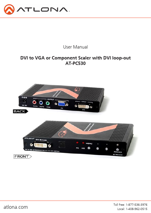
User ManualDVI to VGA or Component Scaler with DVI loop-outAT-PC5301. Introduction .................................................. 22. Features .................................................. 23. Package Contents .................................................. 24. Applications .................................................. 25. Specification .................................................. 36. Panel Descriptions .. (4)6.1 Front Panel .................................................. 46.2 Rear Panel .................................................. 47. DVI-D connector Pin Assignment .................................................. 58. OSD Operation .................................................. 59. Connection Diagram .................................................. 610. Support Resolution .................................................. 711. Safety Information .................................................. 812. Warranty .................................................. 913. Atlona Product Registration .. (10)TABLE OF CONTENTSAtlona Technologies new AT-PC530 is an innovative Scaler designed to convert DVI (digital) signal into variety of HDTV or Computer resolutions through Component or VGA outputs. This unique scaler/converter handles input and output signal at resolutions up to 1920x1200 or 1080p. The PC530 is featured with an On Screen Display selection to enhance optimal video performances. Along with being HDCP compliant, the AT-PC530 support DVI resolution from VGA (640x480) up to WUXGA (1920x1200) and scale it to Component or VGA to resolutions up to 1080p or 1920x1200.• Atlona DVI (Digital) to VGA or Component Scaler • IR Remote control• 5V DC power adaptor (universal)•Operation Manual• DVI signal to be displayed on HDTV• The AT-PC530 is able to accept DVI resolution from 640x480 to 1920x1200 and scaler them up or downto either component video or vga at resolutions up to 1920x1200 or 1080p.• The output resolution can be selected via IR Remote control or though On Screen Display• The On Screen Display allows user to adjust brightness, contrast, color, RGB level and H-V position.• PC530 features a Noise Reduction and Overscan/ Underscan adjustments.Note: The DVI-D input is HDCP compliant which means if input is HDCP encrypted then DVI loop-out will also be HDCP encrypted. In this case the PC/component output will be turned off.INTRODUCTIONPACKAGE CONTENTSAPPLICATIONSFEATURESSPECIFICATIONS1. Front Panel1. DVI BYPASS: The DVI Bypass allows users to connect a local display. The resolution on the bypass output would be the same as incoming resolution.2. IR receiver: IR receiver picks up IR signal from the included remote control3. PC & HD LED Indicator: These LEDs shows the output selection timing format. Only one Red LED will illumi-nate according to the setting.4. Menu & +/- buttons: Press menu button to show On Screen Display selection on the display and press + or – buttons to move to your desire setting.5. Power button & LED Indicator: Press this button to switch on the desired device or set it to standby mode. The LED will illuminate in green when the power is on and red when power is off.2. Rear Panel1. DC 5V: Plug the 5V DC power supply into the unit and connect the adaptor to an AC wall outlet.2. OUTPUT Cr/Pr, Cb/Pb & Y/HD: Connect a component video display to this output3. OUTPUT PC: Connect a VGA cable to a monitor4.INPUT DVI: Connect with DVI cable from your sourcePANEL DESCRIPTION152341234DVI-D Receptacle ConnectorDVI-D CONNECTOR PIN ASSIGNMENTOSD OPERATIONCONNECTION DIAGRAMSUPPORT RESOLUTIONSafeguardsPrecautionsFCC regulations state that any unauthorized changes or modifications to this equipment, not expressly approved by the manufacturer, could void the user’s authority to operate this equipment.Operate this product using only the included external power supply. Use of other power supplies could impair performance, damage the product, or cause fires.In the event of an electrostatic discharge this device may automatically turn off. If this occurs, unplug the device and plug it back in.Protect and route power cords so they will not be stepped on or pinched by anything placed on or against them. Be especially careful of plug-ins or cord exit points from this product.Avoid excessive humidity, sudden temperature changes or temperature extremes.Keep this product away from wet locations such as bathtubs, sinks, laundries, wet basements, fish tanks, and swimming pools.Use only accessories recommended by Atlona to avoid fire, shock, or other hazards.Unplug the product before cleaning. Use a damp cloth for cleaning and not cleaning fluid or aerosols.Such products could enter the unit and cause damage, fire, or electric shock. Some substances may also mar the finish of the product.Never open, remove unit panels, or make any adjustments not described in this manual. Attempting to do so could expose you to dangerous electrical shock or other hazards. It may also cause damage to your AT-PC530. Opening the product will void the warranty.Do not attempt to service the unit. Disconnect the product and contact your authorized Atlona reseller or contact Atlona directly.To reduce the risk of electric shock, do not expose this product to rain or moisture If the wall plug does not fit into your local power socket, hire an electrician to replace your obsolete socket.Do not modify the wall plug. Doing so will void the warranty and safety features.This equipment should be installed near the socket outlet and the device should be easily accessible in the case it requires disconnection.SAFETY INFORMATIONAtlona, Inc. (“Atlona”) Limited Product Warranty PolicyCoverageAtlona warrants its products will substantially perform to their published specifications and will be free from defects in materials and workmanship under normal use, conditions and service.Under its Limited Product Warranty, Atlona, at its sole discretion, will either:A) repair or facilitate the repair of defective products within a reasonable period of time, restore products to theirproper operating condition and return defective products free of any charge for necessary parts, labor and shippingORB) replace and return, free of charge, any defective products with direct replacement or with similar products deemed by Atlona to perform substantially the same function as the original productsORC) refund the pro-rated value based on the remaining term of the warranty period, not to exceed MSRP, in caseswhere products are beyond repair and/or no direct or substantially similar replacement products exist.Repair, replacement or refund of Atlona’s products is the purchaser’s exclusive remedy and Atlona’s liability does not extend to any other damages, incidental, consequential or otherwise.This Limited Product Warranty extends to the original end-user purchaser of Atlona’s products and is non-transferrable to any subsequent purchaser(s) or owner(s) of these products.Coverage PeriodsAtlona’s Limited Product Warranty Period begins on the date of purchase by the end-purchaser. The date contained on the end-purchaser ‘s sales or delivery receipt is the proof purchase date.Limited Product Warranty Terms – New Products• 10 years from proof of purchase date for hardware/electronics products purchased on or after June 1, 2013• 3 years from proof of purchase date for hardware/electronics products purchased before June 1, 2013• Lifetime Limited Product Warranty for all cable productsLimited Product Warranty Terms – Refurbished (B-Stock) Products• 3 years from proof of purchase date for all Refurbished (B-Stock) hardware and electronic products purchased on or after June 1, 2013RemedyAtlona recommends that end-purchasers contact their authorized Atlona dealer or reseller from whom they purchased their products. Atlona can also be contacted directly. Visit for Atlona’s contact information and hours of operation. Atlona requires that a dated sales or delivery receipt from an authorized dealer, reseller or end-purchaser is provided before Atlona extends its warranty services. Additionally, a return merchandise authorization (RMA) and/or case number, is required to be obtained from Atlona in advance of returns.Atlona requires that products returned are properly packed, preferably in the original carton, for shipping. Cartons not bearing a return authorization or case number will be refused. Atlona, at its sole discretion, reserves the right to reject any products received without advanced authorization. Authorizations can be requested by calling 1-877-536-3976 (US toll free) or 1-408- 962-0515 (US/international) or via Atlona’s website at .ExclusionsThis Limited Product Warranty excludes:• Damage, deterioration or malfunction caused by any alteration, modification, improper use, neglect, improperpacking or shipping (such claims must be presented to the carrier), lightning, power surges, or other acts of nature.• Damage, deterioration or malfunction resulting from the installation or removal of this product from any installation, any unauthorized tampering with this product, any repairs attempted by anyone unauthorized by Atlona to makesuch repairs, or any other cause which does not relate directly to a defect in materials and/or workmanship of thisproduct.• Equipment enclosures, cables, power supplies, batteries, LCD displays, and any accessories used in conjunction with the product(s).• Products purchased from unauthorized distributors, dealers, resellers, auction websites and similar unauthorizedchannels of distribution.Atlona, Inc Product RegistrationThank you for purchasing this Atlona product. - We hope you enjoy it and will take an extra few moments to register your new purchase.Registration creates an ownership record if your product is lost or stolen and helps ensure you’ll receive notification of performance issues and firmware updates.At Atlona we respect and protect your privacy, assuring you that your registration information is completely secure. Atlona product registration is completely voluntary and failure to register will not diminish your limited warranty rights.To register go to: /registrationDisclaimersThis Limited Product Warranty does not imply that the electronic components contained within Atlona’s products will not become obsolete nor does it imply Atlona products or their electronic components will remain compatible with any other current product, technology or any future products or technologies in which Atlona’s products may be used in conjunction with. Atlona, at its sole discretion, reserves the right not to extend its warranty offering in instances arising outside its normal course of business including, but not limited to, damage inflicted to its products from acts of god.Limitation on LiabilityThe maximum liability of Atlona under this limited product warranty shall not exceed the original Atlona MSRP for its products. To the maximum extent permitted by law, Atlona is not responsible for the direct, special, incidental or consequential damages resulting from any breach of warranty or condition, or under any other legal theory. Somecountries, districts or states do not allow the exclusion or limitation of relief, special, incidental, consequential or indirect damages, or the limitation of liability to specified amounts, so the above limitations or exclusions may not apply to you.Exclusive RemedyTo the maximum extent permitted by law, this limited product warranty and the remedies set forth above are exclusive and in lieu of all other warranties, remedies and conditions, whether oral or written, express or implied. To the maximum extent permitted by law, Atlona specifically disclaims all implied warranties, including, without limitation, warranties of merchantability and fitness for a particular purpose. If Atlona cannot lawfully disclaim or exclude implied warranties under applicable law, then all implied warranties covering its products including warranties of merchantability and fitness for a particular purpose, shall provide to its products under applicable law. If any product to which this limited warranty applies is a “Consumer Product” under the Magnuson-Moss Warranty Act (15 U.S.C.A. §2301, ET SEQ.) or otherapplicable law, the foregoing disclaimer of implied warranties shall not apply, and all implied warranties on its products, including warranties of merchantability and fitness for the particular purpose, shall apply as provided under applicable law.Other ConditionsAtlona’s Limited Product Warranty offering gives legal rights, and other rights may apply and vary from country to country or state to state. This limited warranty is void if (i) the label bearing the serial number of products have been removed or defaced, (ii) products are not purchased from an authorized Atlona dealer or reseller. A comprehensive list of Atlona’s authorized distributors, dealers and resellers can be found at . Toll free: 1-877-536-3976Local: 1-408-962-0515。
蓝海华腾变频器V5

蓝海华腾变频器V5矢量化V/F控制方式:将矢量控制技术与V/F控制相结合,既有矢量控制的优异性能又对电机参数不敏感。
启动转矩:0.50Hz 180%额定转矩调速范围:1:100 稳速精度:± 0.5%0.50Hz可控制电机150%额定转矩稳定运行。
无速度传感器矢量控制方式:精确的无速度传感器矢量控制技术真正实现了交流电机解耦,使运行控制直流电机化。
启动转矩:0.25Hz 180%额定转矩调速范围:1:200 稳速精度:± 0.2%无速度传感器矢量控制下优异的控制性能真正实现了交流电机解耦,使运行控制直流电机化。
图1为无速度传感器矢量控制下电机四象限运行,转矩、电流、转速和直流母线电压快速响应,电机稳定运行。
电机额定负载下实现0.1s指令加减速。
电机正反转过零速切换时,电流无相位突变和震荡,转速无脉动。
母线电压控制平稳,在无能耗制动的条件下减速亦能提供快速可靠的制动能力。
尤其适合于:数控机床、喷泉控制、编织机、提花机等各类往复运行设备。
图1 0Hz→正转50Hz→0Hz→反转50Hz→0Hz的急加减速四象限运行母线电压速度电流转矩真正实现无跳闸运行优异的电流和电压控制技术,以0.1s指令反复交替加速和减速,变频器稳定无跳闸运行。
超强的负载能力,在任意加减速时间和任意冲击负载条件下,变频器稳定无跳闸运行。
短时过载能力强,200%的额定负载条件下可连续工作0.5s,150%的额定负载条件下可连续工作1分钟。
智能的模块温度控制,最大限度发挥变频器带负载能力。
尤其适用于:注塑机节能改造、起重/提升设备、数控机床、轧机、高炉上料等重载设备。
母线电压图2 任意加减速和稳态运行,电流电压控制稳定不会跳闸保护电流独特的电网瞬时掉电处理在电网瞬时掉电期间,通过电机回馈母线的能量使得变频器持续运行不停机,直到电源正常后继续运行。
变频器运行期间长时间掉电导致停机后,下次上电变频器可提供告警信息。
支持掉电后再上电变频器自动运行功能。
G2446资料

LCMLiquid Crystal Display Modules Seiko Instruments GmbHDot Matrix Liquid Crystal Display ModulesCHARACTER TYPE • FEATURES :• Slim, light weight and low power consumption • High contrast and wide viewing angle• Built-in controller for easy interfacing• LCD modules with built-in EL or LED backlightM1641L1642L1614M1632L1652L2012H : HorizontalV : VerticalT : Thickness (max)*2 : With external temperature compensation *3 : Including EL backlight*4 : Based on normal temperature rangeSince our policy is one of continues improvements we reserve the right to change the specifications for the products in the catalogue w ithout notice.G1226G2446G1216 G321DG1213G649DG242CG324EFor logic: typ. mA, max. mA For LC drive: typ. mA, max. mA Others ( ) : typ. mA, max. mACHECK LIST FOR CUSTOM DESIGNED LCD MODULE1. Company2. Application3. Customer Specified Part No.6. Display ContentsInternal External UnnecessaryCompensation range: 0°C to 50°C °C to °C20. ScheduleCharacter type: characters linesCharacter font x dots + cursor Character pitch x mm Dot pitch x mm Dot size x mm Graphics (Full dot) type: x dots Dot pitch x mm Dot size x mm Segment type: digits lines Others12. Current Consumption13. Contrast Adjustment8. Driving MethodMultiplexing:1/ duty, 1/ bias Frame frequency: HzA xB : Module size x mmE xF : Viewing area x mm P x Q : Active display area x mm C : Length between mounting holes mm D : Length between mounting holes mmM : Diameter of mounting hole mm H : Total thickness mmH1 : Upper thickness mm H2 : Lower thickness mmViewing angle: 6 o'clock 12 o'clock o'clock Type: TN FSTN (Black and white)STN ( Yellow green Gray Blue)Chromaticity coordinates( ≤ x ≤ , ≤ y ≤ )Positive type Negative typeReflective Transflective Transmissive OthersGray scale: Yes gray scale No Preferential specifications:Response time t on ms ( °C) t off ms ( °C) Viewing angle deg. ( °C) Contrast ( °C) OthersLCD surface finishing: Normal Anti-glarePolarizer color: Normal (neutral gray) Red Green Blue9. ICLCD driver: Specified UnspecifiedSegment driver (Manufacturer ) Common driver (Manufacturer )Controller: Internal ExternalType No. (Manufacturer )MPU: Internal ExternalType No. (Manufacturer )RAM: Internal ExternalType No. /Memory size (Kbit) (Manufacturer )Single power supply: 5V V 2 power supplies15. Input/Output TerminalsSpecifying allocation: Yes No Specifying position: Yes NoInternal External UnnecessaryMethod: Temp. compensation circuit VolumeEstimate:Sample: Delivery , Quantity: pcs Mass production: Target price:Delivery , Total quantity: pcs 17. ConnectorInternal External UnnecessaryType No. (Manufacturer )18. Backlight19. OthersInternal External Unnecessary EL: Green WhiteLED: Yellow green Amber CFL: WhiteIncandescent lamp OthersBacklight type Edge backlight type Brightness: cd/m 2Inverter: Internal External Unnecessary Power supply voltage VCurrent consumption (backlight included) mA Brightness control: Yes No4. DesignNew Modified : Manufacturer , Part No. , Remarks Equivalent: Manufacturer , Part No. , Remarks7. LCD Panel10. Power Supply11. Temperature Compensation Circuit14. Temperature RangeOperating temperature range: 0°C to 50°C °C to °C Storage temperature range: - 20°C to 60°C °C to °C16. Weighttyp. g, max. gV1:Horizontal length of viewing area mm V2:Vertical length of viewing area mm CN**: Terminal length mm CS**:Terminal length mm **CN or CS=0 in case of one side terminal type.CC: Terminal length mm SE,SW,SN,SS : Seal width(According to design or manufacturing condition:about 2.0 mm to 4.0 mm)Liquid Crystal DisplaysOperating temperature rangeWith temperature compensation circuit (or volume) ( 0°C to 50°C °C to °C) Without temperature compensation circuit( 0°C to 50°C °C to °C) ( - 20°C to 60°C °C to °C)CHECK LIST FOR CUSTOM DESIGNED LCD1. Company2. Application3. Customer Specified Part No.6. Panel Form7. Display ModeViewing angle : 6 o'clock 12 o'clock o'clock Type: TN FSTN (Black and white)STN: ( Yellow green Gray Blue)Chromaticity coordinates ( ≤ x ≤ , ≤ y ≤ ) Positive type Negative typeReflective Transflective Transmissive Preferential specifications:Response time t on ms ( °C) t off ms ( °C) Viewing angle deg. ( °C) Contrast ( °C) OthersSurface finishing: Normal Anti-glareColor: Normal (neutral gray) Red Green BlueFront polarizer : Attached type Separate type Rear polarizer : Attached type Separate type8. PolarizerF1: Horizontal length of upper glass mm F2: Vertical length of upper glass mm R1: Horizontal length of lower glass the same as F1R2*: Vertical length of lower glass mm *R2 is generally longer than F2 when terminals are with pin.TF, TR***: Thickness of glass mm ***Standard type: 1.1 mm or 0.7 mmTU: Thickness of LCD mm End seal: Right Left Right or Left9. Driving Method11. Terminal Connecting Method10. Temperature Range13. Schedule12. OthersStatic Multiplexing: (1/ duty, 1/ bias) Operating voltage (V opr) : V Frame frequency: HzDriving IC: (Manufacturer )4. DesignNew Modified: Manufacturer , Part No. , Remarks Equivalent: Manufacturer , Part No. , Remarks5. Panel DimensionsEstimate:Sample : Delivery , Quantity : pcs Mass production : Target price :Delivery , Total quantity: pcs Quantity per month: pcsRubber connector (Zebra rubber) Pin: DIL SILPitch ( 2.54 mm) Length ( mm) Heat seal: Equipped UnnecessaryPrint (Characters, lines, masks etc.) : Yes No Protective film:Yes (Color: Red Translucent Transparent) No Chamfering (for heat-seal connector) : Yes (Position: ) (Quantity: )No• Terminal• Chamfering • DrillingYes NoYes No- Type A -- Type B -Display area Display area Displaying surfaceRubber (zebra) connector typePin typeLiquid Crystal Display ModulesEL (Electroluminescent Lamp) backlightLED (Light Emitting Diode) backlightFeatures: EL: thin, inverter requiredLED: long service life, low voltagedriving, no inverter required REFLECTIVE/TRANSFLECTIVE/TRANSMISSIVE LCDPOSITIVE/NEGATIVE MODETN TYPE/STN TYPE/FSTN TYPESTRUCTURE AND FEATURE OF LCD MODULE WITH BACKLIGHTPOWER SUPPL YCFL (Cold Cathode Fluorescent Lamp) backlightFeatures: high brightness, long service life, inverter required(G2446,G242C)Backlight type*- 2V (min)Character modules (single power supply)G2446,G242C (Built-in DC-D C conv.) G321D, G324E and G649DCharacter Modules(Dual power supply) Y1206 and G1226* Negative voltage should be variable forNote 1:Contrast can be adjusted by VR.Note 2:For module with backlight, power supplyfor backlight is necessary.PrecautionsSafety Instructions•If the LCD panel is damaged, be careful not to get the liquid crystal in your mouth and not to be injured by crushed glasses.•If you should swallow the liquid crystal, first, wash your mouth thoroughly with water, then, drink a lot of water and induce vomiting, and then, consult a physician.•If the liquid crystal should get in your eye, flush your eye with running water for at least fifteen minutes.•If the liquid crystal touches your skin or clothes, re-move it and wash the affected part of your skin or clothes with soap and running water.•EL or CFL backlight is driven by a high voltage with an inverter. Do not touch the connection part or the wir-ing pattern of the inverter.•Do not use inverters without a load or in the short-cir-cuit mode.•Use the LCD module within the rated voltage to pre-vent overheating and/or damage. Also, take steps to ensure that the connector does not come off. Handling Precautions•Since the LCD panel has glass substrate, avoid apply-ing mechanical shock or pressure on the module. Do not drop, bend, twist or press the module.•Do not soil or damage LCD panel terminals.•Since the polarizer is made of easily-scratched mate-rial, be careful not to touch or place objects on the dis-play surface.•Keep the display surface clean. Do not touch it with your skin.•CMOS LSI is used in the LCD module. Be careful of static electricity.•Do not disassemble the module or remove the liquid crystal panel or the panel frame.•Do not damage the film surface of the EL lamp; other-wise the lamp will be damaged by humidity.•To set an EL lamp in an LCD module, push the EL lamp with its emitting side up, without pushing the rub-ber connectors too hard. If you damage them, the LCD module may not work properly.Mounting and Designing•To protect the polarizer and the LCD panel, cover the display surface with a transparent plate (e.g., acrylic or glass) with a small gap between the transparent plate and the display surface.•Keep the module dry. Avoid condensation to prevent the transparent electrodes from being damaged.•Drive LCD panel with AC waveform in which DC ele-ment is not included to prevent deterioration in the LCD panel.•Contrast of LCD varies depending on the ambient tem-perature. To offer the optimum contrast, LC drive volt-age should be adjusted. LCD driven in a high duty ratio must be provided with drive voltage adjustment method.•Mount a LCD module with the specified mounting part/ holes.•Design the equipment so that input signal is not ap-plied to the LCD module while power supply voltage is not applied to it.•Do not locate the CFL tube and the lamp lead wire close to a metal plate or a plated part inside the equip-ment. Otherwise stray capacity causes a drop in volt-age, decreasing the brightness and the ability to start-up.Cleaning•Do not wipe the polarizer with a dry cloth, as it may scratch the surface.•Wipe the LCD panel gently with a soft cloth soaked with a petroleum benzine.•Do not use ketonic solvents (ketone and acetone)or aromatic solvents (toluene and xylene), as they may damage the polarizer.Storing•Store the LCD panel in a dark place, where the tem-perature is 25°C±10°C and the relative humidity be-low 65%. If possible, store the LCD panel in the pack-aging situation when it was delivered.•Do not store the module near organic solvents or cor-rosive gases.•Keep the module (including accessories) safe from vi-bration, shock and pressure.•Use an LCD module with built-in EL backlight within six months of delivery.•EL backlight is easily affected by environmental con-ditions such as temperature and humidity; the quality may deteriorate if stored for an extended period of time. Contact Seiko Instruments GmbH for details.•Some parts of the backlight and the inverter generate heat. Take care so that the heat does not affect the liquid crystal or any other parts.•Dust particles attached to the surface of the LCD or the surface of the backlight degrade the display qual-ity. Be careful to keep dust out in designing the struc-ture as well as in handling the module.•Black or white air-bubbles may be produced if the LCD panel is stored for long time in the lower temperatureor mechanical shocks are applied onto the LCD panel. On This Brochure•Seiko Instruments GmbH reserves the right to make changes without notice to the specifications and mate-rials contained herein.•The colors of the products reproduced herein may be different from the actual colors. Check color on actual products before using the product.•The information contained herein shall not be repro-duced in whole or in part without the express written consent of Seiko Instruments GmbH•The products described herein are designed for con-sumer equipment and cannot be used as part of any device or equipment which influences the human bodyor requires a significantly high reliability, such as physi-cal exercise equipment, medical equipment, disaster prevention equipment, gas related equipment, vehicles, aircraft and equipment mounted on vehicles.元器件交易网。
海尔 PX700 压力传感器电压输出型号说明书

350 DP41-E, DP25B-E, DP460-E
MODEL NO. CH-4620
PRICE DESCRIPTION
$95 Reference Book: Rotordynamics Prediction in Engineering
Comes with complete operator’s manual.
81 (3.19)
67 (2.63)
56 (2.19)
34 (1.31)
64 (2.5)
37 (1.44)
B
Enclosure
31 (1.19)
SPECIFICATIONS
4 to 20 mA Output Excitation: 12 to 32 Vdc unregulated
Output: 4 to 20 mA
2000 to 10,000 psi
A Dimension
127 (5.00)
160 (6.28)
24 (0.9375)
PRESSURE PORT
Dimensions: mm (in)
Typical Life: 100 million cycles
Operating Temperature: -18 to 71°C (0 to 160°F)
350 DP41-E, DP25B-E, DP460-E 350 DP41-E, DP25B-E, DP460-E 350 DP41-E, DP25B-E, DP460-E 350 DP41-E, DP25B-E, DP460-E
Weight: 672 g (23.7 oz) to 1000 psi 686 g (24.2 oz) from 2000 psi
- 1、下载文档前请自行甄别文档内容的完整性,平台不提供额外的编辑、内容补充、找答案等附加服务。
- 2、"仅部分预览"的文档,不可在线预览部分如存在完整性等问题,可反馈申请退款(可完整预览的文档不适用该条件!)。
- 3、如文档侵犯您的权益,请联系客服反馈,我们会尽快为您处理(人工客服工作时间:9:00-18:30)。
Q
Class I (N) : More than 30pF : Q > 1000 30pF & below : Q > 400+20C (C: Capacitance, pF)
Tan Withstanding Voltage
Class II (X) : 2.5% maximum Class II (Z/E) : 4.0% maximum No dielectric breakdown or mechanical breakdown 200V < V < 500V : 200% rated voltage 500V < V < 1000V : 150% rated voltage 1000 < V : 120% rated voltage for 1-5sec. Current is limited to less than 50mA.
元器件交易网
HIGH VOLTAGE CHIP CAPACITORS
1. PART NO. EXPRESSION :
V5X SERIES
V5X103J-B-10
(a) (b) (c) (d) (e) (f)
(a) Chip Size (b) Temp. Coefficient :55°C to +125°C ) (c) Capacitance code : 103 = 10000pF
V5X SERIES
NOTE : Specifications subject to change without notice. Please check our website for latest information.
15.01.2008
SUPERWORLD ELECTRONICS (S) PTE LTD
PERFORMANCE
TEST CONDITION
No abnormal exterior appearance 10,000M or 500/C product whichever is smaller
Visual inspection V < 500V, Rated Voltage V > 500V, Applied 500Vdc Charge Time: 60sec is applied less than 50mA current
V5X SERIES
V5X223 -E-10 V5X273 -E-10 V5X333 -E-10 V5X393 -E-10 V5X473 -E-10 V5X563 -E-10 V5X683 -E-10 Tolerance code : : C : ±0.25pF D : ±0.50pF J : ±5% K : ±10% M : ±20%
V5X SERIES
V5X103 -C-10 V5X123 -C-10 V5X153 -C-10 V5X183 -C-10 V5X223 -C-10 V5X273 -C-10 V5X333 -C-10 V5X393 -C-10 V5X473 -C-10 V5X563 -C-10 V5X683 -C-10 V5X104 -C-10 V5X124 -C-10 V5X154 -C-10 V5X184 -C-10 V5X224 -C-10 Tolerance code : : C : ±0.25pF D : ±0.50pF J : ±5% K : ±10% M : ±20%
H
15.01.2008
SUPERWORLD ELECTRONICS (S) PTE LTD
PG. 1
元器件交易网
HIGH VOLTAGE CHIP CAPACITORS
6. ELECTRICAL CHARACTERISTICS : ( Rated Voltage : 200Vdc ) Part Number V5X103 -B-10 V5X123 -B-10 V5X153 -B-10 V5X183 -B-10 V5X223 -B-10 V5X273 -B-10 V5X333 -B-10 V5X393 -B-10 V5X473 -B-10 V5X563 -B-10 V5X683 -B-10 V5X104 -B-10 V5X124 -B-10 V5X154 -B-10 V5X184 -B-10 V5X224 -B-10 Tolerance code : : C : ±0.25pF D : ±0.50pF J : ±5% K : ±10% M : ±20% Capacitance ( pF ) 10000 12000 15000 18000 22000 27000 33000 39000 47000 56000 68000 100000 120000 150000 180000 220000
NOTE : Specifications subject to change without notice. Please check our website for latest information.
15.01.2008
SUPERWORLD ELECTRONICS (S) PTE LTD
PG. 3
元器件交易网
HIGH VOLTAGE CHIP CAPACITORS
6. ELECTRICAL CHARACTERISTICS : ( Rated Voltage : 1KVdc ) Part Number V5X103 -J-10 V5X123 -J-10 V5X153 -J-10 V5X183 -J-10 V5X223 -J-10 V5X273 -J-10 V5X333 -J-10 V5X393 -J-10 Tolerance code : : C : ±0.25pF D : ±0.50pF J : ±5% K : ±10% M : ±20% Capacitance ( pF ) 10000 12000 15000 18000 22000 27000 33000 39000
V5X SERIES
NOTE : Specifications subject to change without notice. Please check our website for latest information.
15.01.2008
SUPERWORLD ELECTRONICS (S) PTE LTD
Class I : Char. N Class II : Char. X E Z Temp. Range -55°C ~ +125°C -30°C ~ +85°C +10°C ~ +85°C Cap. Change (%) ±15% +22% ~ -56% +22% ~ -56% Temp. Range -55°C ~ +125°C Cap. Change (%) ±30ppm/°C
0.30 Min. 2.20 - 2.40 1.80 - 2.30 1.00 - 1.20
3. SCHEMATIC :
4. MATERIALS : b a
Ag(100%) Ni(100%)-1.5um(min.) Sn(100%)-3.0um(min.)
(a) Body : Ceramic (b) Termination : Ag/Ni/Sn
Adhesive Strength of Termination
No indication of peeling shall occur on the terminal electrode
* Withstanding voltage testing requires immersion of the element in a isolation fluid prevent arching on the chip surface, at voltage over 1000Vdc.
Temperature Capacitance Coefficient
Capacitance
Within the specified tolerance [Class I (N) & Class II]
Class I : C < 100pF : Freq. = 1MHz±10%, Voltage = 1.0±0.2Vrms C > 100pF : Freq. = 1KHz±10% Class II : X : Freq. = 1KHz±10%, Voltage = 1.0±0.2Vrms Z/E : Freq. = 1KHz±10%, Voltage = 1.0±0.2Vrms Perform a heat temp. at 150±5°C for 30min. then place room temp. for 24±2hr
(d) Tolerance code (e) Voltage code : B = 200Vdc (f) 10 : Lead Free
2. CONFIGURATION & DIMENSIONS :
A D L G
B
C
PCB Pattern Unit:m/m
A
B
C
D
G
H
L
3.20±0.30 2.50±0.20 2.60 Max.
NOTE : Specifications subject to change without notice. Please check our website for latest information.
15.01.2008
SUPERWORLD ELECTRONICS (S) PTE LTD
PG. 4
PG. 5
元器件交易网
HIGH VOLTAGE CHIP CAPACITORS
7. RELIABILITY & TEST CONDITION :
V5X SERIES
ITEM