DSP第二章课件
合集下载
DSP第二章5
其幅度谱和相位谱分别为
X (e j ) | sin 5 / 2 | , () 2 arg[ sin 5 / 2]
sin( / 2)
sin( / 2)
上午4时33分
11
其图形如下
上午4时33分
12
3 序列的傅立叶变换的性质
因序列的傅立叶变换是Z变换在 z 1 的单位圆上的特例,故所有Z变换的性 质对傅立叶变换都成立。
2
若序列x(n)绝对可和,即
x(n)e jn x(n)
n
n
则其Fourier变换X (e j ) 存在且连续,是 序列的z变换在单位圆上的值:
X (e j ) X (z) ze j
x(n)e jn
n
上午4时33分
3
若序列的Fourier变换 X (e j )存在且连续, 且是其z变换在单位圆上的值,则序列 x(n)一定绝对可和,将 X (e j ) 展成Fourier 级数,其系数即为x(n):
x(n)e jn
4
e jn
n
n0
1 e j5 1 e j
j 5 j 5
j 5
e
2 (e 2
j j
e 2 )
j
e 2 (e 2 e 2 )
e
j 2
sin 5
2
sin 25 Nhomakorabea 2 k
k为整数
2 k
上午4时33分
25
2-10 设 X e j 是如图所示的 x n 信号的傅 里叶变换,不必求出 X e j ,试完成下列
计算:
(1) X e j0
dspPPT课件

2.10 在片外围电路
00: 16位字
01: 10位字
缓冲同步串行口BSP
01: 8位字 01: 12位字
内部发送时钟分频系数 BSPC的MCM=1时,CLKX 由频率为CLKOUT/(CLKDV+1)
的片内时钟源驱动
➢工作模式 非缓冲模15~式10
帧同步脉冲极性设置位
自动缓9 冲模8 式7 0:高6 电平有5 效1:低4~电0 平有效
第10页/共35页
第 二McBS章P 硬件 结 构
DR
RSR
RBR
2.10DX在片外围XSR电路
扩展
DRR
压缩
DXR
多通道缓冲串行口McBSP
SPCR
➢结CL构KX 图 CLKR FSX FSR CLKS
时钟和帧 RCR
16
同步信号
位
发生与控 XCR
外
制
SRGR
设 总
PCR
线
多通道选 择
MCR RSCREGR
提 供 片 选 信 号 . M c B S P 的 时第2钟9页停/共3止5页模 式 选 为 C L K S T P = 1 0 ,
第二章 硬件结构
2.10 在片外围电路
多通道缓冲串行口McBSP
➢McBSP的应用实例
程序首次初始化TMS320VC5410,使数据页指针 DP=0,并
CLKS 引脚状 态位
DX引 脚状态 位
DR引 脚状态 位
发送帧同步脉冲 的极性位. 0: 高电平有效 1: 低电平有效
发送时钟极性 位. 0: 上升沿采样 1: 下降沿采样
第16页/共35页
第二章 硬件结构
2.10 在片外围电路
DSP课件第1、2章

?
Digital Signal Processing
DSP
Digital Signal Processor
DSP(数字信号处理) DSP(数字信号处理)是一门涉及多门学科并广泛应用于 很多科学和工程领域的新兴学科。 很多科学和工程领域的新兴学科。 数字信号处理包括两个方面的内容: 数字信号处理包括两个方面的内容 1.算法的研究 . 2.数字信号处理的实现 √ .
1)DSP技术的发展 DSP技术的发展
DSP芯片诞生于20世纪70年代末,经历了以下三个阶段。 DSP芯片诞生于20世纪70年代末,经历了以下三个阶段。 芯片诞生于20世纪70年代末 第一阶段,DSP的雏形阶段(1980年前后)。 第一阶段,DSP的雏形阶段(1980年前后)。 的雏形阶段 年前后 1978年AMI公司生产出第一片DSP芯片S2811。 公司生产出第一片DSP芯片S2811 1978年AMI公司生产出第一片DSP芯片S2811。 1979年美国Intel公司发布了商பைடு நூலகம்可编程DSP器件 年美国Intel公司发布了商用可编程DSP器件Intel2920, 1979年美国Intel公司发布了商用可编程DSP器件Intel2920, 由于内部没有单周期的硬件乘法器 使芯片的运算速度、 内部没有单周期的硬件乘法器, 由于内部没有单周期的硬件乘法器,使芯片的运算速度、数据处 理能力和运算精度受到了很大的限制。运算速度大约为单指令周 理能力和运算精度受到了很大的限制。运算速度大约为单指令周 200~250ns,应用领域仅局限于军事或航空航天部门 于军事或航空航天部门。 期200~250ns,应用领域仅局限于军事或航空航天部门。 2010 退出
2010
退出
1.2 DSP技术的发展及现状 1.2 DSP技术的发展及现状
DSP原理与应用-课件
多处理器结构
本书的 封面
走信息路 读北邮书
1.2.2 与CPU、MCU、FPGA/CPLD的比较
与CPU、MCU、FPGA/CPLD的比较
尽管微处理器集成度很高,但仍需要较多的外围电路, 使得其性价比、体积、功耗都都比DSP大的多。 但单片机的控制接口种类比DSP多,适用于以控制为主 的模数混合设计,同时在成本上单片机的价格也低的 多。
(4)图形/图像处理:如三维图像变换、模式识别、
图像增强、动画、电子地图等。
(5)自动控制:如机器人控制、自动驾驶、发动机控
制、磁盘控制等。
本书的
封面
走信息路 读北邮书
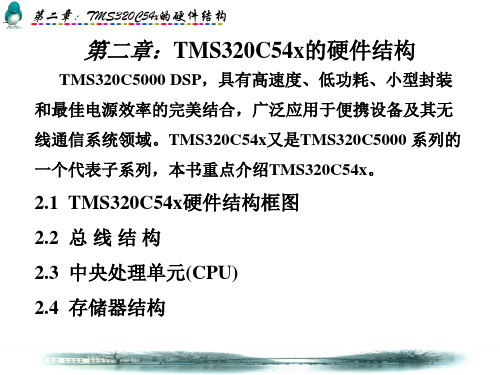
2.1 TMS320C54x的硬件结构特性
2.1.1 TMS320C54X的硬件结构 2.1.2 TMS320C54X的主要特性
走信息路 读北邮书
1.2.1 DSP芯片的特点 1.2.2 与CPU、MCU、FPGA/CPLD的比较 1.2.3 DSP产品简介
走信息路 读北邮书
本书的 封面
1.1
数字信号处理概述
数字信号处理概述
DSP可以代表数字信号处理技术(Digital Signal Processing),也 可以代表数字信号处理器(Digital Signal Processor
走信息路 读北邮书
本书的 封面
2.1.2 TMS320C54x的主要特性
1
CPU
2
存储器
3 片内外设
4 指令系统
走信息路 读北邮书
本书的 封面
2.1.2
CPU
CPU
(1) 先进的多总线结构(1条程序总线、3条数据总线和4
条地址总线)。
(2) 40位算术逻辑运算单元(ALU)。包括1个40位桶形移
本书的 封面
走信息路 读北邮书
1.2.2 与CPU、MCU、FPGA/CPLD的比较
与CPU、MCU、FPGA/CPLD的比较
尽管微处理器集成度很高,但仍需要较多的外围电路, 使得其性价比、体积、功耗都都比DSP大的多。 但单片机的控制接口种类比DSP多,适用于以控制为主 的模数混合设计,同时在成本上单片机的价格也低的 多。
(4)图形/图像处理:如三维图像变换、模式识别、
图像增强、动画、电子地图等。
(5)自动控制:如机器人控制、自动驾驶、发动机控
制、磁盘控制等。
本书的
封面
走信息路 读北邮书
2.1 TMS320C54x的硬件结构特性
2.1.1 TMS320C54X的硬件结构 2.1.2 TMS320C54X的主要特性
走信息路 读北邮书
1.2.1 DSP芯片的特点 1.2.2 与CPU、MCU、FPGA/CPLD的比较 1.2.3 DSP产品简介
走信息路 读北邮书
本书的 封面
1.1
数字信号处理概述
数字信号处理概述
DSP可以代表数字信号处理技术(Digital Signal Processing),也 可以代表数字信号处理器(Digital Signal Processor
走信息路 读北邮书
本书的 封面
2.1.2 TMS320C54x的主要特性
1
CPU
2
存储器
3 片内外设
4 指令系统
走信息路 读北邮书
本书的 封面
2.1.2
CPU
CPU
(1) 先进的多总线结构(1条程序总线、3条数据总线和4
条地址总线)。
(2) 40位算术逻辑运算单元(ALU)。包括1个40位桶形移
dsp课件Chapter2

Chapter 2, Slide 17 Dr. Naim Dahnoun, Bristol University, (c) Texas Instruments 2004
Using the Load Instructions
Before using the load unit you have to be aware that this processor is byte addressable, which means that each byte is represented by a unique address. Also the addresses are 32-bit wide. Data
Chapter 2, Slide 9 Dr. Naim Dahnoun, Bristol University, (c) Texas Instruments 2004
Register File - A
Register File A A0
40
A1
A2 A3
a1 x1 prod Y . . .
Y =
n = 1
Specifying Register Names
Register File A A0
40
A1
A2 A3
a1 x1 prod Y . . .
Y =
n = 1
an * xn
.M .L
MPY ADD
.M .L
A0, A1, A3 A4, A3, A4
A15
32-bits
The registers A0, A1, A3 and A4 contain the values to be used by the instructions.
DSP技术及应用最新版精品课件第2章
第二章:TMS320C54x的硬件结构 ----2.3 中央处理单元(CPU)
2.3.2. CPU运算部件(6个) (1)算术逻辑单元(ALU)
功能:① 完成二进制补码的算术运算: ② ALU可完成布尔运算; ③ 同时完成两个1Hale Waihona Puke bit运算(具有两个16位的ALU)
组成:ALU组成框图见下图 输入:X端(DB、移位器输出)
• 17位并行乘法器,用于单周期乘法/累加(MAC)运算。
• 比较、选择、存储单元(CSSU):加速Viterbi译码的执行 。
• 指数编码器:在单个周期内计算40位累加器中数值的指数。
•双地址生成器:同时进行三个读操作和一个写操作。
单独的数据地址产生单元(DAGEN) 单独的程序地址产生单元(PAGEN)
第二章:TMS320C54x的硬件结构
表2.2 各种寻址方式所用到的总线
读/写方式
程序读 程序写 单数据读 双数据读 长数据(32 位)读 单数据写 数据读/数据写 双数据读/系数读 外设读 外设写
地址总线
PAB CAB DAB EAB √
√
√
√
√
√①
√②
√
√√
√√
√
√
√
程序总线
数据总线
PB
CB DB EB
(3)桶形移位器
功能:能把输入的数据进行0 ~31bit左移和0 ~16bit右移 用途:位提取、数字定标、扩展算术和溢出保护等 移位数的方式有三种:
▪ 用一个立即数(-16~15)表示。 ▪ 用ST1的ASM位表示,共5位,移位数为-16~15。 ▪ 用T寄存器中最低6位的数值(移位数为-16~31)表示。
Y端(CB、A、B、T) 输出:40位,到A、B 控制或状态:溢出方式 OVM ,C16, C, OVA, OVB, TC
DSP应用技术之二.ppt
数字信号处理系列课程
—— DSP应用技术
DSP 应用技术之二
刘明
数字信号处理系列课程
—— DSP应用技术
二 TMS320C2000处理器
2.1 TMS320C2000各系列DSP概述 2.2 芯片内部结构 2.3 常规外部引脚 2.4 程序控制 2.5 中断控制 2.6 存储器与I/O空间 2.7 片内外设
DSP类型 32位定点 16位定点
特性
150MIPS,32×32位的乘法累加器, 外设中断扩展模式,SCI、SPI、 CAN、12位AD(80ns)、McBSP、 watchdog、内部flash存储器,1.9V 内核电压
40MIPS,16×16位乘法累加器,中 断控制器,SCI、SPI、CAN、10位 AD(375ns)、McBSP、watchdog、 内部Flash存储器,3.3V内核电压
用SETC或CLRC指令,可以对其中某些位置1或清0。
数字信号处理系列课程
—— DSP应用技术
状态寄存器ST0
15 14 13 12
11 10 9 8 7 6 5 4 3 2 1 0
ARP
OV OVM 1 INTM
DP
R/W–x
R/W–0 R/W–x
R/W–1
R/W–x
状态寄存器ST1
15 14 13 12
数字信号处理系列课程
—— DSP应用技术
2. 输入定标部分
功能:将来自存储器的16位数据左移0~16位变成32 位送往中央算术逻辑单元(CALU)。
移位方法:均进行左移,左移后,低位LSB用0填入; 没有使用的高位MSB根据状态寄存器ST1的符号扩展模式 位SXM决定:
当SXM=0,用0填入; 当SXM=1,符号扩展。
—— DSP应用技术
DSP 应用技术之二
刘明
数字信号处理系列课程
—— DSP应用技术
二 TMS320C2000处理器
2.1 TMS320C2000各系列DSP概述 2.2 芯片内部结构 2.3 常规外部引脚 2.4 程序控制 2.5 中断控制 2.6 存储器与I/O空间 2.7 片内外设
DSP类型 32位定点 16位定点
特性
150MIPS,32×32位的乘法累加器, 外设中断扩展模式,SCI、SPI、 CAN、12位AD(80ns)、McBSP、 watchdog、内部flash存储器,1.9V 内核电压
40MIPS,16×16位乘法累加器,中 断控制器,SCI、SPI、CAN、10位 AD(375ns)、McBSP、watchdog、 内部Flash存储器,3.3V内核电压
用SETC或CLRC指令,可以对其中某些位置1或清0。
数字信号处理系列课程
—— DSP应用技术
状态寄存器ST0
15 14 13 12
11 10 9 8 7 6 5 4 3 2 1 0
ARP
OV OVM 1 INTM
DP
R/W–x
R/W–0 R/W–x
R/W–1
R/W–x
状态寄存器ST1
15 14 13 12
数字信号处理系列课程
—— DSP应用技术
2. 输入定标部分
功能:将来自存储器的16位数据左移0~16位变成32 位送往中央算术逻辑单元(CALU)。
移位方法:均进行左移,左移后,低位LSB用0填入; 没有使用的高位MSB根据状态寄存器ST1的符号扩展模式 位SXM决定:
当SXM=0,用0填入; 当SXM=1,符号扩展。
DSP第2章 'C54x的硬件结构2

2013年8月15日
DSP原理及应用
6
3.工作方式状态寄存器PMST
主要设定和控制处理器的工作方式和存储器的配置,反映 处理器的工作状态。
15~7 6 5 4 AVIS 3 2 1 0 SST
IPTR MP/MC OVLY
DROM CLKOFF SMUL
中 断 向 量 指 针
CPU 工 作 方 式 选 择 位
③ 暂存器SPRAM。
2013年8月15日
DSP原理及应用
14
特殊功能寄存器
功能:主要用于程序的运算处理和寻址方式的选
择和设定。地址范围:0000H~001FH。 外设寄存器 ’C5402的CPU寄存器共有27个,CPU访问这 功能:用来控制片内外设电路的状态和存放数据。 些寄存器时,不需要插入等待时间。 地址范围:0020H~005FH。 包括串行口通信控制寄存器组、定时器定时控 暂存器SPRAM 制寄存器组、时钟周期设定寄存器组等。 功能:用来暂存变量。地址范围:0060H~007FH。
中断屏蔽寄存器 10H 中断标志寄存器 11H 保留 ( 用于测试 ) 12H 保留 ( 用于测试 ) 13H 保留 ( 用于测试 ) 14H 保留 ( 用于测试 ) 15H 状态寄存器0 16H 状态寄存器1 17H 累加器A低字(15~0位) 18H 累加器A高字(31~16位) 19H 累加器A保护位(39~32位) 1AH 累加器B低字(15~0位) 1BH 累加器B高字(31~16位) 1CH 累加器B保护位(39~32位) 1DH 暂存寄存器 1EH DSP原理及应用 状态转移寄存器 1FH
2013年8月15日
存储器映像的CPU寄存器, 存储器映像的外设寄存器 特殊功能寄存器
- 1、下载文档前请自行甄别文档内容的完整性,平台不提供额外的编辑、内容补充、找答案等附加服务。
- 2、"仅部分预览"的文档,不可在线预览部分如存在完整性等问题,可反馈申请退款(可完整预览的文档不适用该条件!)。
- 3、如文档侵犯您的权益,请联系客服反馈,我们会尽快为您处理(人工客服工作时间:9:00-18:30)。
The all-element varying bridge produces the most signal for a given resistance change and is inherently linear. It is an industry-standard configuration for load cells which are constructed from four identical strain gages. Bridge may also be driven from constant current sources. Note also that with constant current excitation, all configurations are linear with the exception of the single-element varying case.
CHAPTER 2 BRIDGE CIRCUITS
1.INTRODUCTION
This section discusses the fundamental concepts of bridge circuits. Resistive elements are some of the most common sensors. They are inexpensive to manufacture and relatively easy to interface with signal conditioning circuits. Resistive elements can be made sensitive to temperature, and ing these basic elements, many complex physical phenomena can be measured. Sensor elements’ resistances can range from less 100 to several hundred k .
R+∆ R
R−∆RΒιβλιοθήκη R+ ∆RR−∆R
R + ∆R
.
R+ ∆R
R+∆ R
R−∆R
R+ ∆R
VB VO: 4
∆R ∆R R + 2
VB ∆R ∆R 2 R + 2
∆R VB ∆R R 2
RESISTANCE OF POPULAR SENSORS
Strain Gages Weigh-Scale load Cells Pressure Sensors Relative Humidity 120 ,350 3500 350 -3500 350 -3500 100k –10M 100 ,1000
When R1/R4=R2/R3,the resistance bridge is at a null,irrespective of the mode of exaction (current or voltage,AC or DC),the magnitude of excitation ,the mode of readout(current or voltage), or the impedance of the detector.Therefore, if the ratio of R2/R3 is fixed at K,a null is achieved when R1=K*R4. If R1 is unknown and R4 is an accurately determined variable resistance, the magnitude of R1 can be found by adjusting R4 until null is achieved. Conversely, in sensor-type measurements, R4 may be a fixed reference,and a null occurs when the magnitude of the external variable (strain, temperature, ect.) is such that R1=K*R4.
Resistance Temperature Devices(RTDs) Thermistors
100 -10M
Resistive sensors produce small percentage changes in resistance in response to a change in a physical variable such as temperature or force.Platinum RTDs have a temperature coefficient of about 0.385%/oC. Thus, in order to accurately resolve temperature to 1oC, the measurement accuracy must be much better than 0.385 .
∆R ∆R VB R
( A) Single-Element (B)Two-Element (1) (C)Two-Element (2) (D)Four-Element
In each case, the value of the fixed bridge resistor,R, is chosen to be equal to the norminal value of the variable resietor(s). The deviation of the variable resistor(s) about the norminal value is proportional to the quantity being measured, such as strain (in the case of a strain gage) or temperature (in the case of an RTD). The sensitivity of a bridge is the ratio of the maximum expected chang in the output voltage to the excitation voltage. For instance, if VB =10V , and the fullscale bridge output is 10mV, then the sensitivity is 1mV/V. As the equation indicates, the relationship between the bridge output and resistor is not linear. For example, if R=100 and∆R=0.1 (0.1% change in resistance), the output of the bridge is 2.49875mV for VB=10V.
For the majority of sensor applications employing bridges,however, the deviation of one or more resistors in a bridge from an initial value is measured as an indication of the magnitude (or a change ) in the measured variable. In this case ,the output voltage change is an indication of the resistance change. Because very small resistance changes are common,the output voltage change may be as small as tens of millivolts, even with VB=10V. In many bridge applications there may be two,or even four elements which vary.
THE WHEATSTONE BRIDGE
VB R4 +
R1 R2 V0= VBVB R1 + R 4 R 2 + R3
R3
vo
R2
=
R1 R 2 − R 4 R3 VB R1 R 2 1 + 1 + R3 R 4
R1
AT BALANCE, VO=0 IF
R1 R 2 = R 4 R3
2.Bridge Configurations
Bridges offer an attractive alternative for measuring small resistance changes accurately.The basic Wheatstone bridge(actually developed by S.H. Christie in 1833) is shown below. It consists of four resistors connected to form a quadrilateral. The detector measures the difference between the outputs of two voltage dividers connected across the excitation. A bridge measures resistance indirectly by comparison with a similar resistance. The two principle ways of operating a bridge are as detector or as a device that reads a difference directly as voltage